
TIP:
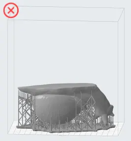
For models that contain internal or enclosed hollows (e.g., a hollow sphere), use a 3D design package to either fill the hollow or add drainage holes to minimize suction during printing.

Orientation can be the difference between a print success and a print failure. In 3D printing, orientation is defined as the alignment of an object within the space of the build volume. It impacts stability, surface finish, and printability.
For the best print results, consider the following tips and guidelines when working with your Formlabs SLA printer.
Model design
A successful 3D print starts with a well designed model. See the design specifications for your printer for best practices to optimize designs and reduce failures.
Preparing the printer
Before starting a print, perform the following checks to reduce the risk of print defects or failures due to debris.
Best practices for model orientation
When setting up a print job, carefully consider how your model is oriented. Printing the same model in different orientations can lead to notably different results in surface finish, print time, and dimensional accuracy. In some cases the orientation of a model can even make the difference between a successful print and a print failure. See Moving and rotating a model in PreForm for more information on how to manipulate models in PreForm.
This section describes some general recommendations for model orientation when printing with Formlabs SLA printers, but not every recommendation applies to every model or print job.
In summary:
Print directly on the build platform
Print parts directly on the build platform whenever possible. This requires at least one flat face, though having small chamfers around the edges of that face may help for part removal. Parts printed directly to the build platform will generally have the least amount of warpage and shrinkage, in addition to using fewer supports.
Since the build platform constrains shrinkage, bottom layers will often be oversized in the XY plane. You may need to adjust your models if a perfect fit is critical. You can still support a part printed directly on the build platform by changing the raft type to None, taking advantage of both the supports and the build platform.
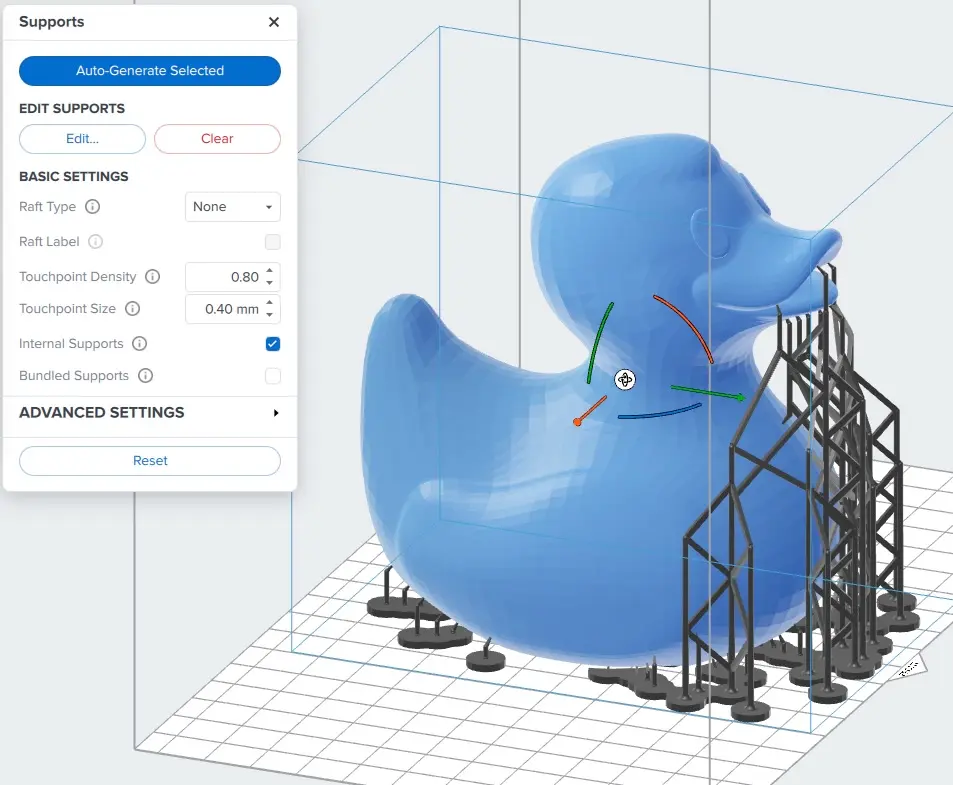
For parts printed directly on the build platform without supports or rafts:
Orient largest regions closest to the build platform
Orienting large, long models with the heavier part of the model towards the build platform allows for more touchpoints to be attached to the model earlier on in the print, reducing the likelihood that the part will rip off the supports.
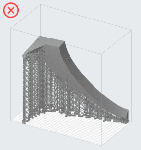
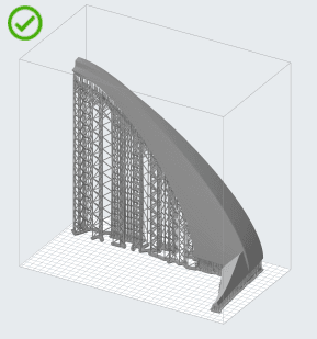
In the orientation on the right, the part of the model with the larger cross-sectional area is printed first, allowing for more touchpoints to be adhered to the model in the early layers of the print. Tilting this part more vertically would also help avoid curling of the flat face at the bottom of the model. For more information, see the section below on orienting models to avoid part warpage.
Avoid merging features
Models with branching features should be oriented so that the branches build off a common base, rather than merging together. This can also be thought of as decreasing the number of minima on the sample.
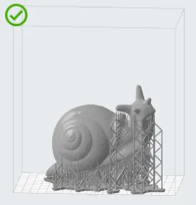
In the orientation on the left, the eyestalks of the snail are first printed as separate features that merge into the head, which may lead to print failures. The orientation on the right is preferred because the eyestalks will build off the head of the snail. This orientation also allows for the most detailed features of the model to be oriented away from the build platform to avoid support marks on the top of the snail's shell.
Prevent suction cups
Hollow models and concave surfaces risk creating a suction cup during printing. Pointing a cavity face-up in PreForm traps air between the printed part and the resin tank, causing suction that makes your part stick and detach.
Use PreForm to view and resolve suction cups.
TIP:
For models that contain internal or enclosed hollows (e.g., a hollow sphere), use a 3D design package to either fill the hollow or add drainage holes to minimize suction during printing.
Reducing print time
Orienting a model at an angle creates supports of varying lengths. If you are printing on a Form 2, you can place the longer supports closer to the wiper side. This decreases the distance the wiper travels during the final layers, reducing the time it takes for your model to print. When printing on a Formlabs LFS printer (e.g., the Form 3 or Form 3L), orienting parts in PreForm to be closer to the mixer side minimizes the distance the LPU needs to travel along the X-axis when printing.
TIP:
Changing a model’s Raft Type can save time in the early layers of a print.
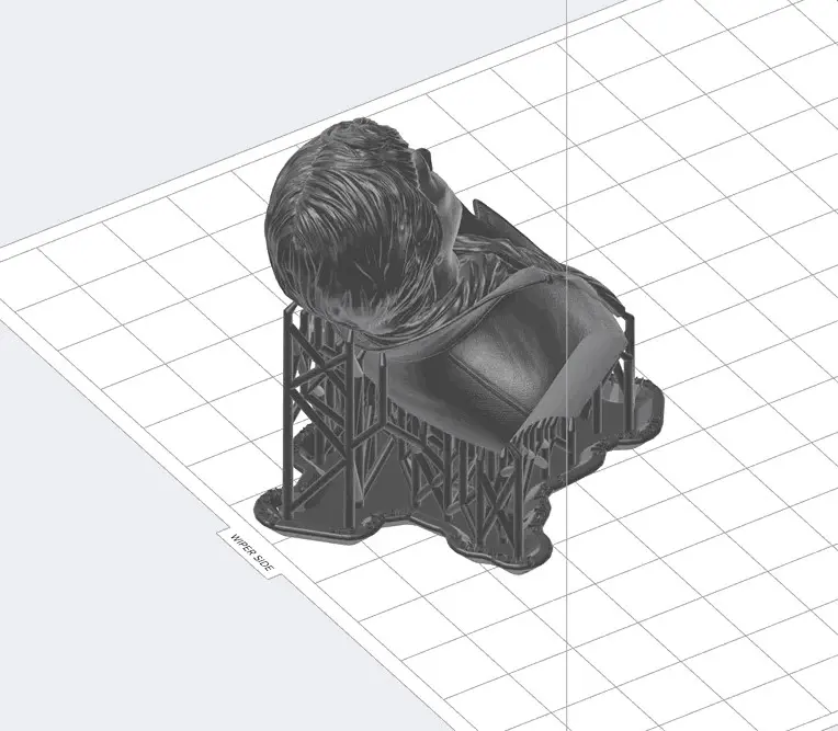
Orienting models to avoid part warpage
Warpage is one of the most common problems in 3D printing, causing parts to be dimensionally inaccurate, have surface defects, or even fail completely early in the printing process. Below is a table of warping artifacts you may see when using a Form 4 or Form 4L generation printer, an explanation of why they occur, and strategies to mitigate or avoid them.
| Print defect | Improper model orientation | Cause | Mitigation strategies |
|---|---|---|---|
Shrinkage from sudden changes in cross-sectional area (also known as “H-bar shrinkage”) 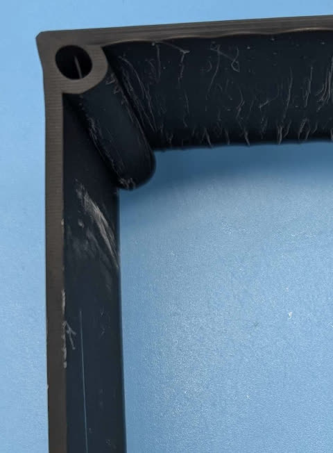 | 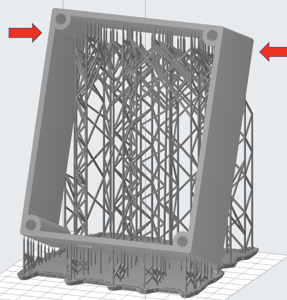 | Shrinkage across a long span or a large cross-sectional area. The figure below shows a model with multiple internal boxes. If it is oriented with the boxes parallel to the build platform, it will warp at the layer that has a sudden increase in cross-sectional area. This concept applies to many geometries, including C-shaped or box-shaped parts. 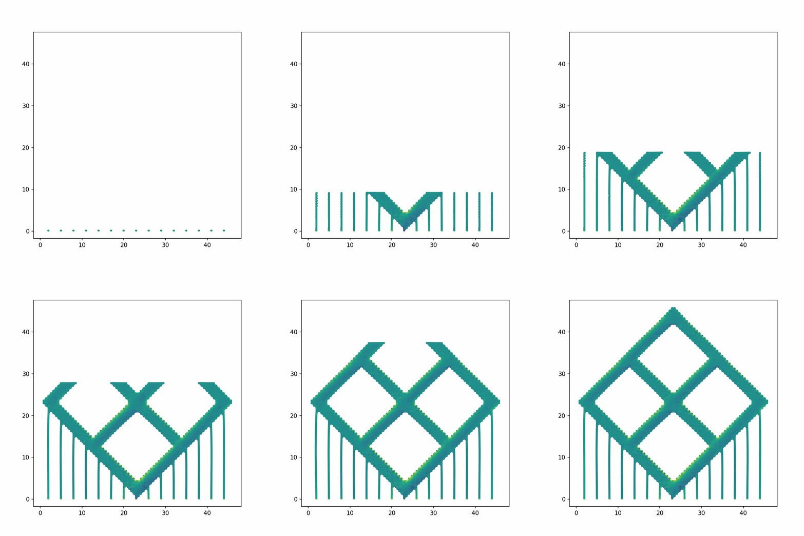
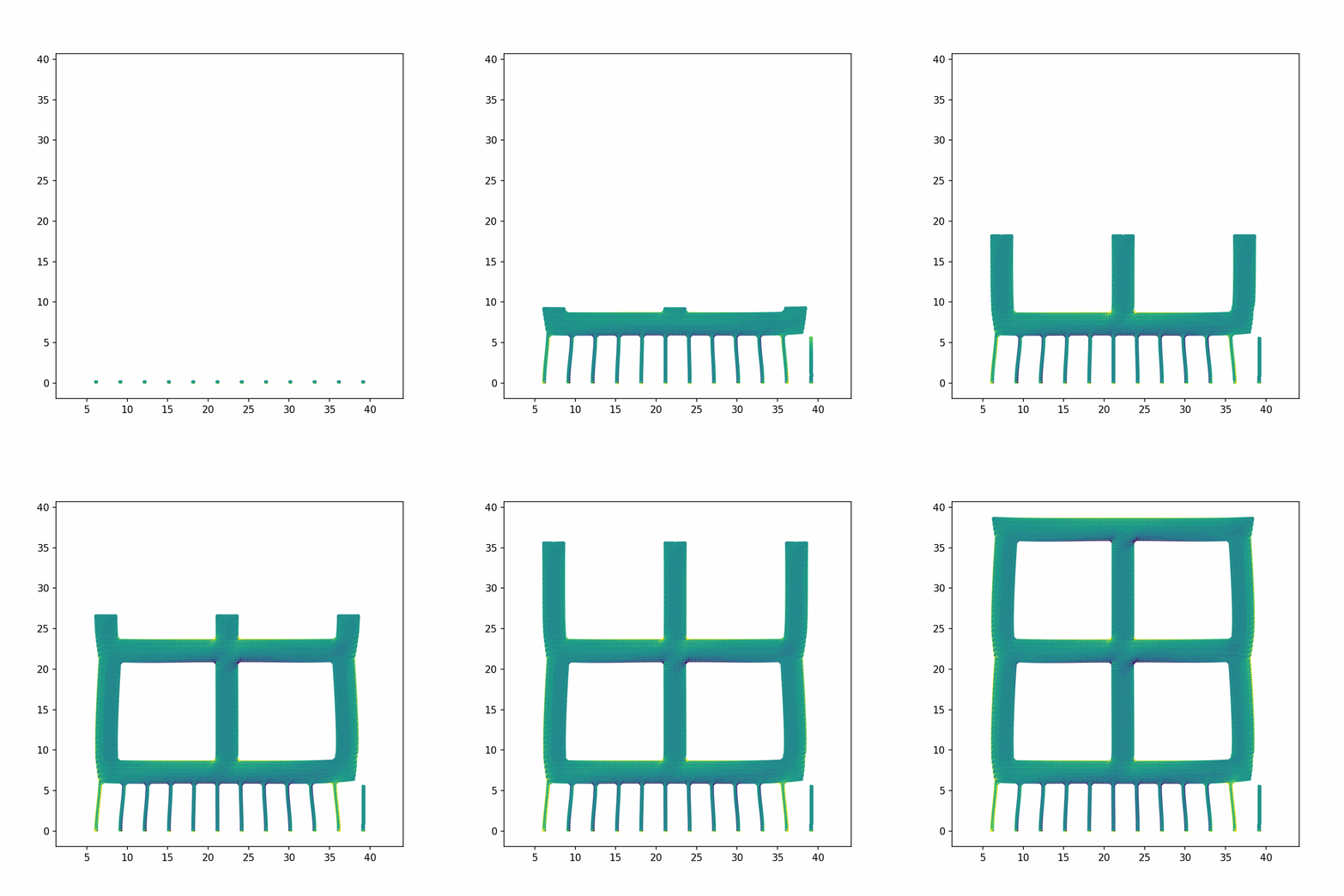
| Reorient the model so it is oriented at 45° to the horizontal, reducing the change in cross-sectional area between layers. Download the FORM file to test the part yourself. 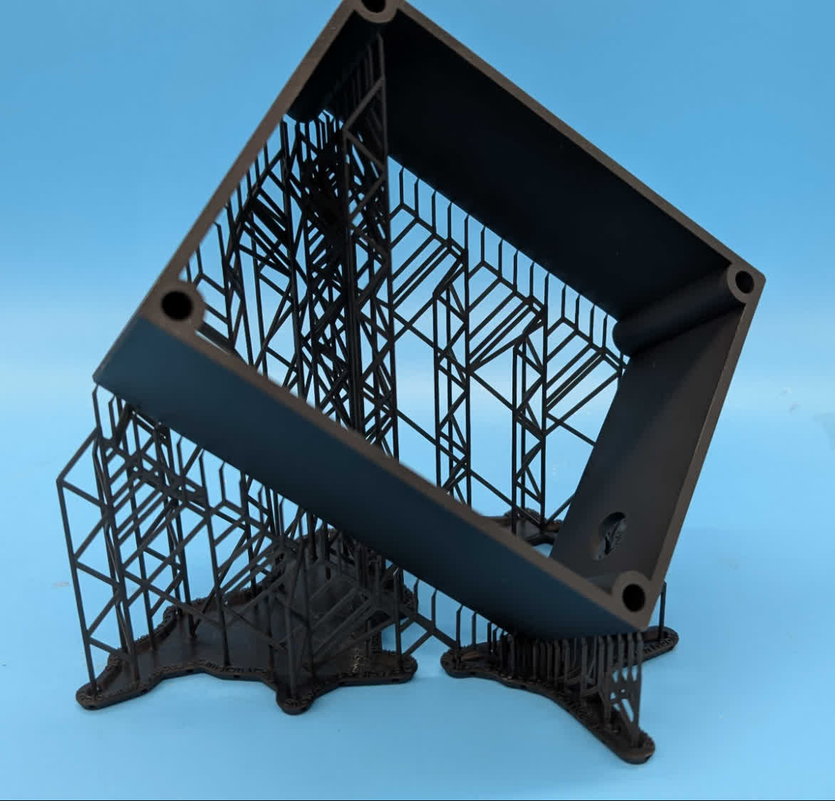 |
Curling of edges 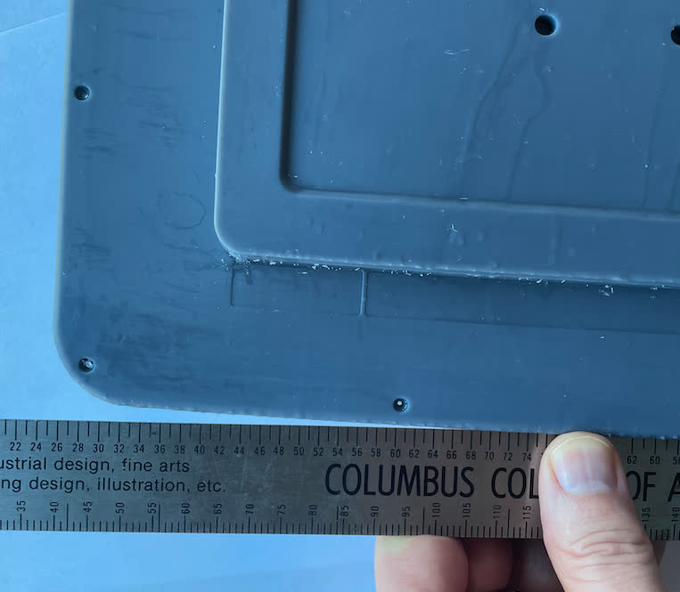 | 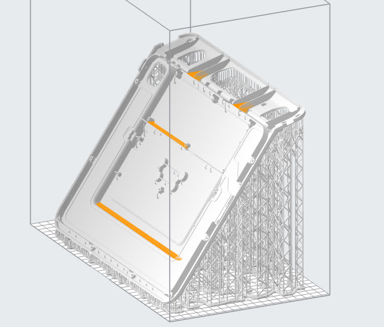 | Each new layer imparts a force on the part as it shrinks. Over time, the build up of these forces can cause the part to warp or break free of the supports. | Reorient the model so it is oriented at 45° to the horizontal, minimizing the shrinkage. Download the FORM file to test the part yourself. 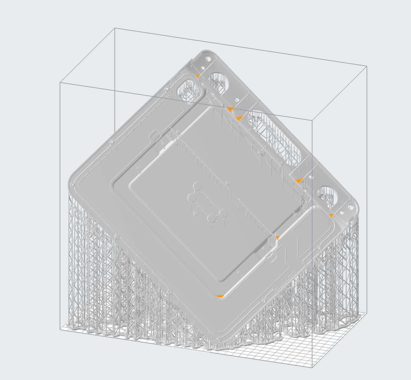 |
Curling of large surfaces 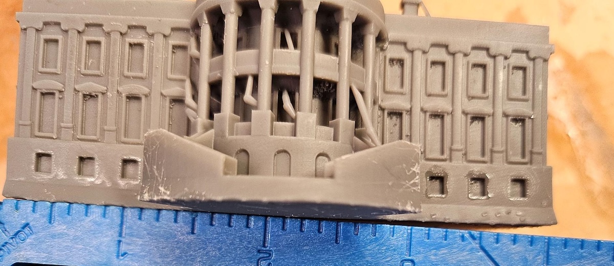 | 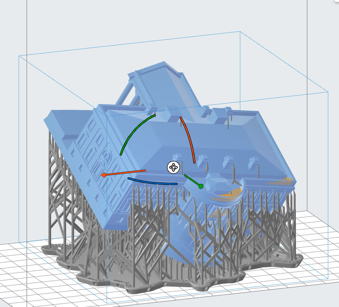 | The forces described above for edge curling can also affect and be seen in bulky parts. | Rotating the largest surface away from the build platform minimizes the cross-sectional area and avoids any larger merging features. Printing directly on the build platform would also likely keep the part flat if the part doesn’t curl away during printing. However, this can cause the bottom layers to be oversized. Download the FORM file to test the part yourself. 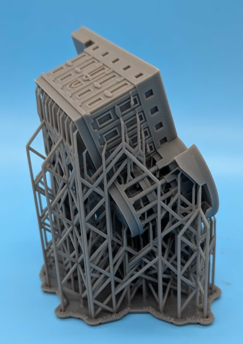 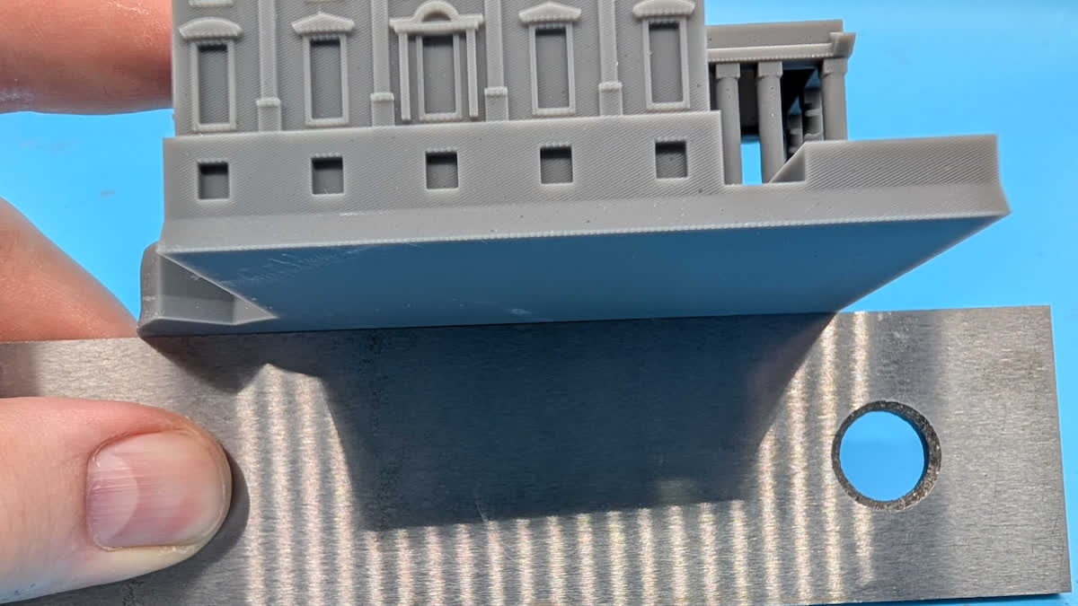 |
Bat-winging 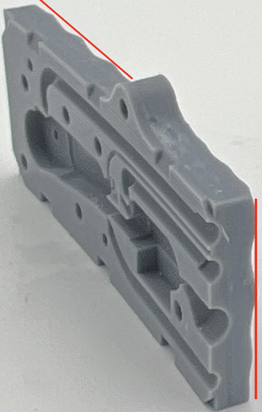 | 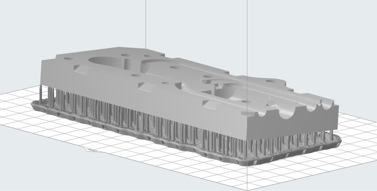 | Faces tilted at a shallow angle relative to the build platform may exhibit “bat wing” distortion, where the part curls away from the build platform at the ends of its long axis. This is caused by insufficient support density. Large spans between the support touchpoints allow for deformation due to printing forces. | Orient parts more vertically. If that is impossible, increase support density and ensure that the touchpoints are spaced evenly. Download the FORM file to test the part yourself. 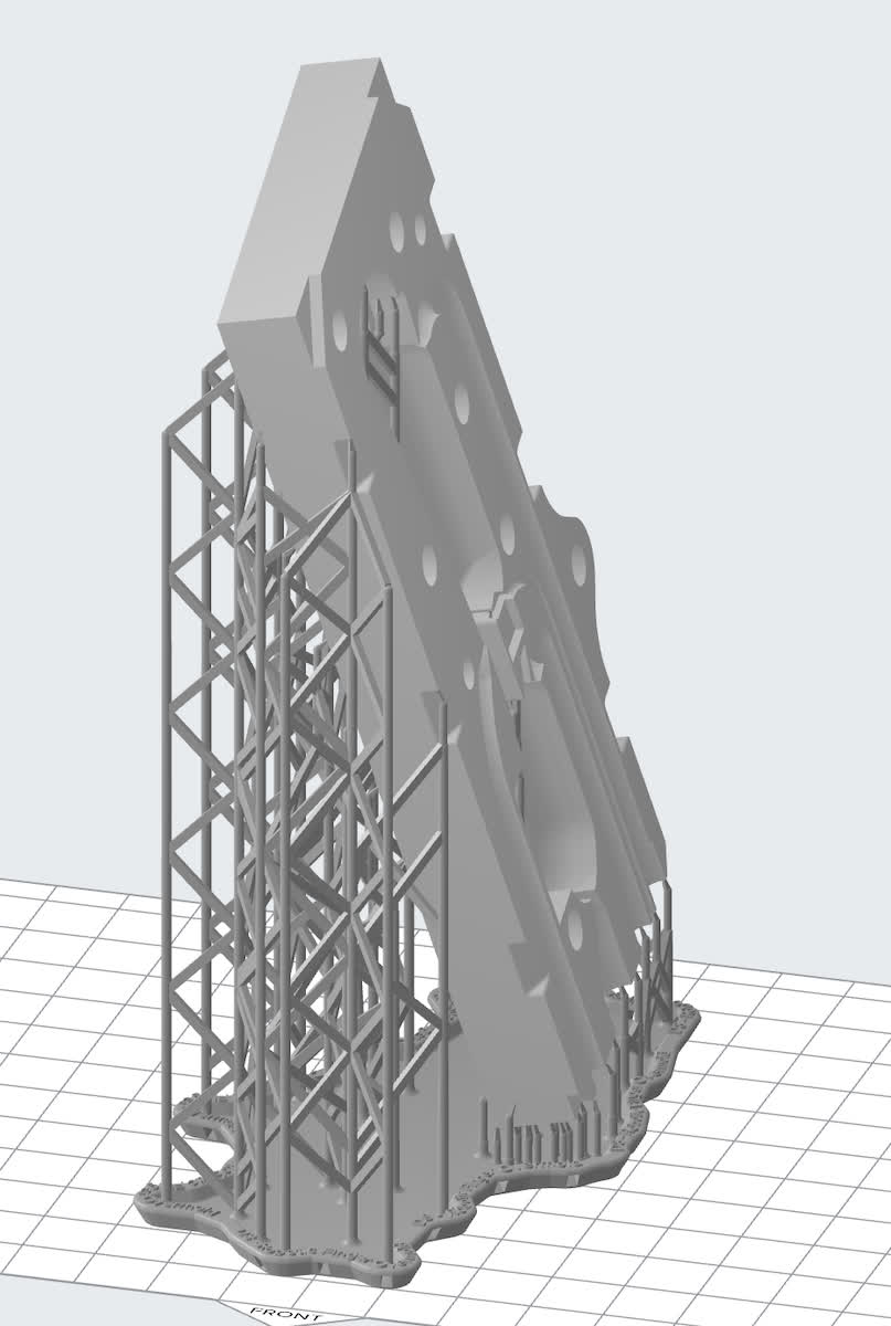 |
Note:
The defects listed above occur during printing, but parts can also sag and warp during post-curing. Sagging occurs when heavy parts are placed into a post-cure chamber, such as a Form Cure or Form Cure L, without sufficient support, resulting in the part drooping as it post-cures. Longer cure times and softer materials are more prone to this defect.
Avoiding surface defects from support touchpoints and the LPU release texture
Orient parts so that surfaces that are complex, aesthetically critical, or need to mate with another part are oriented away from the supports as much as possible.
Parts printed parallel to the build platform may have slight dimpling from the release texture on the Light Processing Unit (LPU). Instead, orient large flat surfaces at a shallow angle relative to the build platform. In PreForm, models can be rotated in 15° increments by holding the Shift key while rotating the part.
Avoiding suction forces from symmetric expanding areas
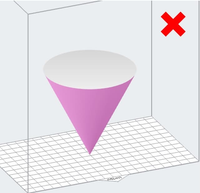
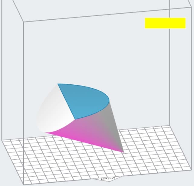
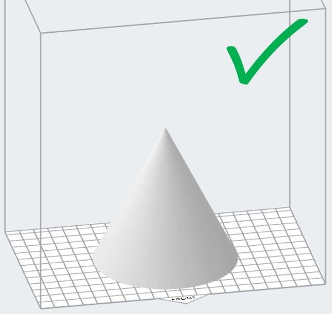
For models with one or more axes of symmetry, such as cones, be careful to avoid expanding areas along that axis. Layers that get progressively larger can create suction forces and cause print defects. Tilt models to avoid expanding areas, placing the thickest areas towards the bottom. If that is not possible, orient them at an angle to avoid the symmetrical expansion.
Examples
The examples below show different models whose geometries could cause the print defects described above, the ideal orientation to avoid those defects, and a picture of the final printed part.
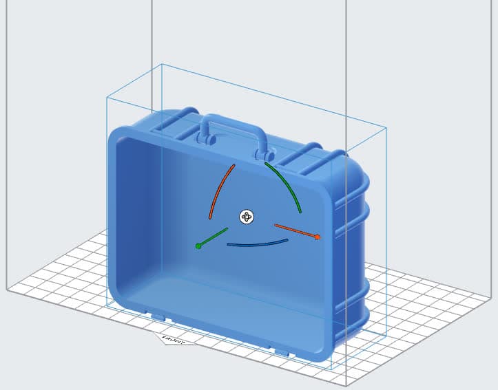
Example 1: Case
This model has multiple geometric and aesthetic features that can make it challenging to properly orient and successfully print. Key considerations for orienting this part include:
Download the FORM file to test the part yourself.
| Ideal orientation | Reasons | Printed part | Flatness |
|---|---|---|---|
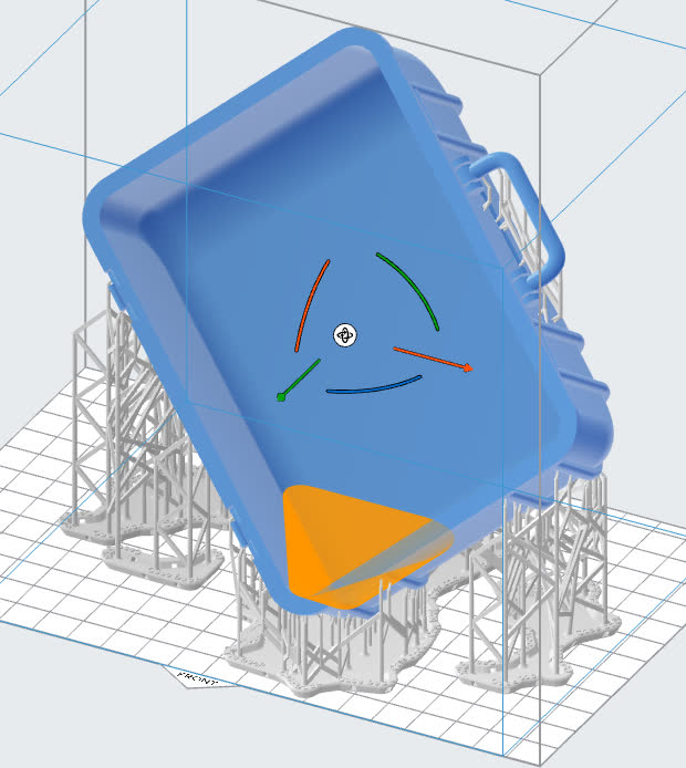 | This orientation generally reduces H-bar shrinkage and warping as well as the number of merging features in the part. This orientation does introduce a cup. To avoid related surface defects, add a drain hole. | 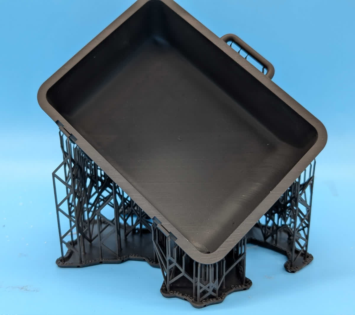 | 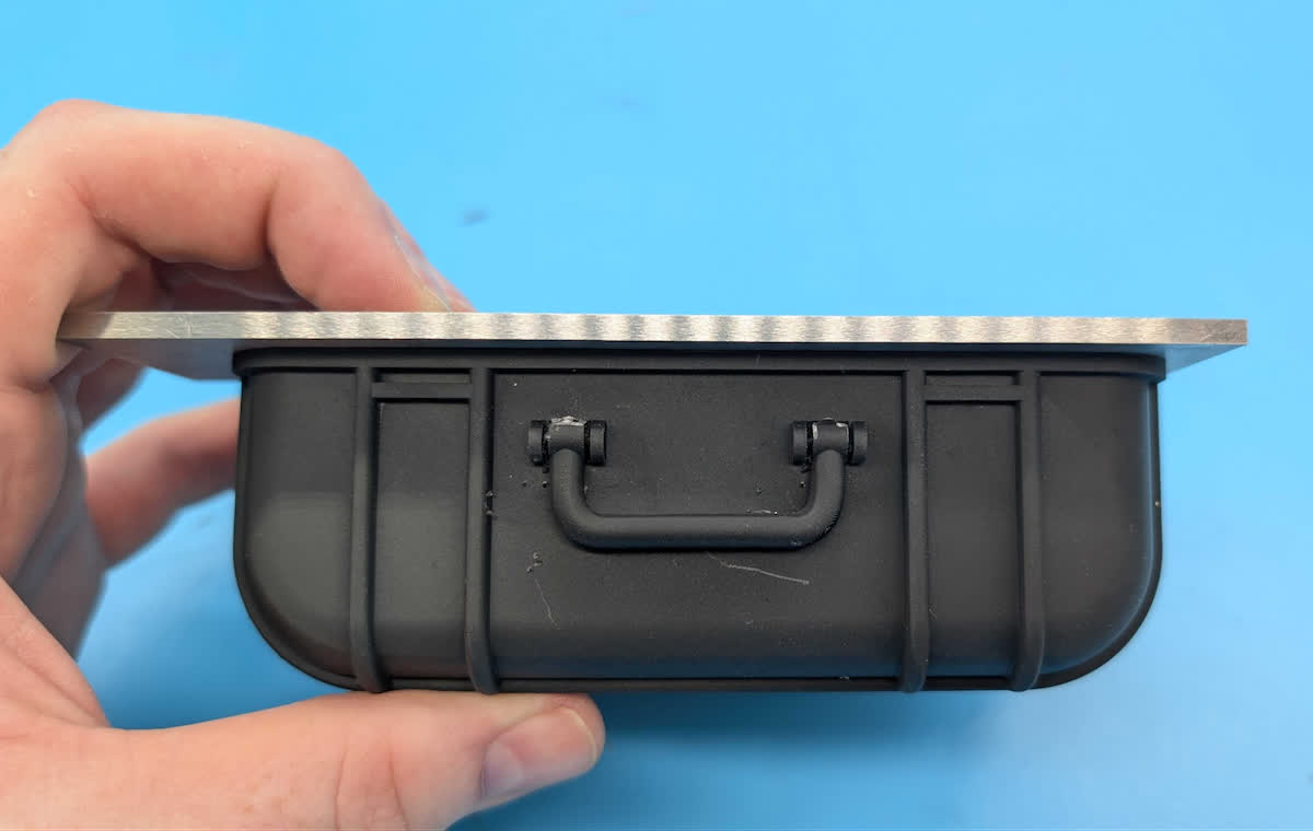
Front of the case printed in the recommended orientation with no warp, shown with a machining parallel for reference.
|
Example 2: Form 2 printer base
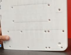
This part can curl dramatically when printed nearly flat or when angled only in a single direction. When it is printed at an angle relative to both the X- and Y-axis, the warpage is dramatically reduced.
Download the FORM file to test the part yourself.
| Ideal orientation | Reasons | Printed part | Flatness |
|---|---|---|---|
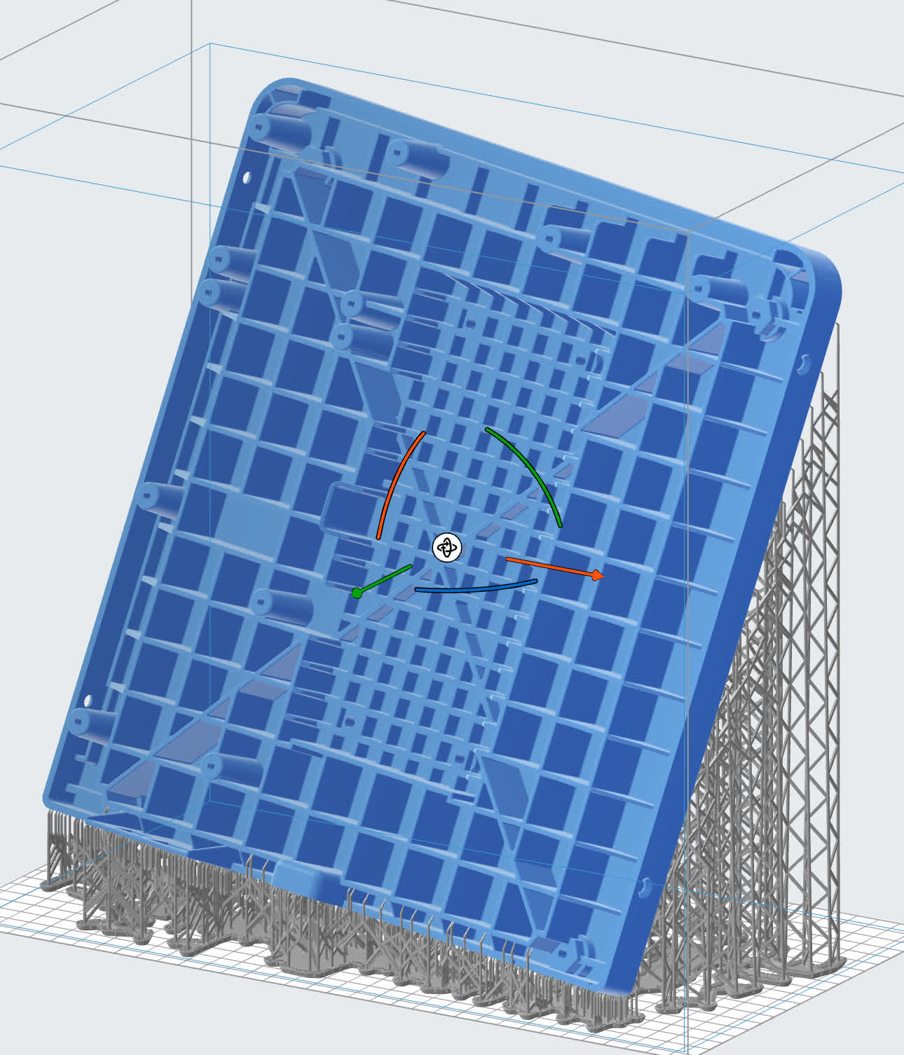 | Shrinkage and internal stresses can cause the entire part to curl upwards, away from the build platform. This is especially noticeable on bottom surfaces. Tilting the part in both the X- and Y-axis reduces the cross-sectional area change as the ribs are printed. | 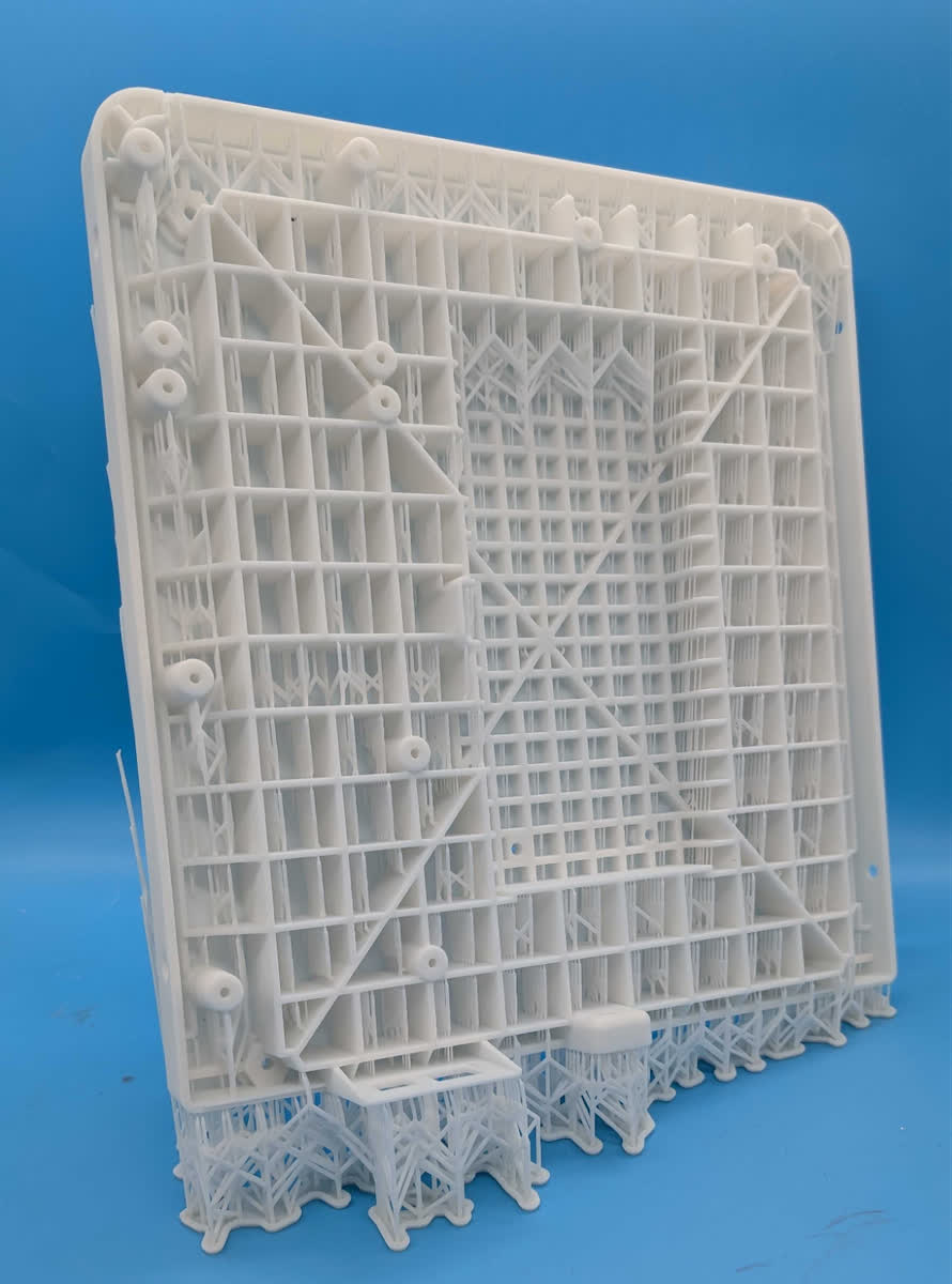 | 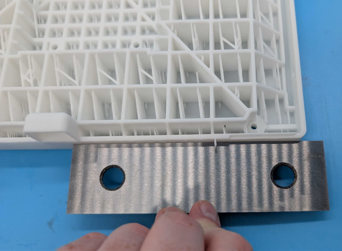
Edge of the part printed in the recommended orientation, shown with a machining parallel for reference. There is still some slight shrinkage along the longest axis. Ideally, that edge would have been tilted at 45°, but that would not fit in the printer’s print volume.
|
Example 3: Resin tank frame
This part nearly fills the print volume of the Form 4L, constraining the possible orientations. Rotating about a single axis creates a strong H-bar at the top of the part, resulting in buckled corners. To avoid this, use as much of the second axis as possible.
Download the FORM file to test the part yourself.
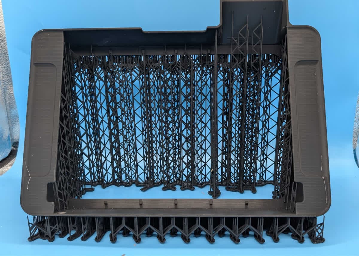
| Ideal orientation | Reasons | Printed part | Flatness |
|---|---|---|---|
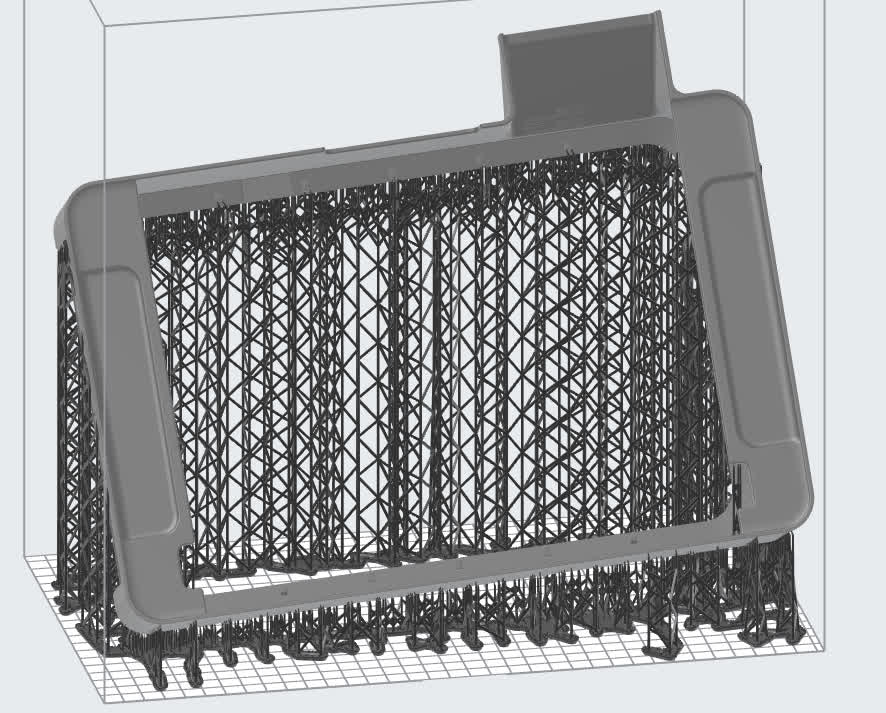 | Minimizes changes in cross-sectional area between layers and avoids any larger merging features. | 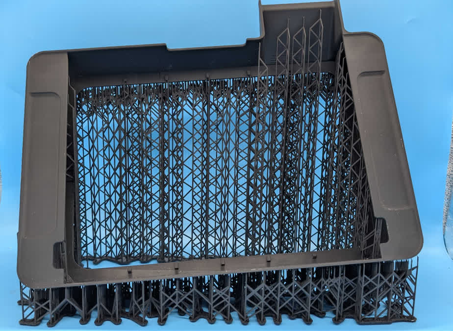 | 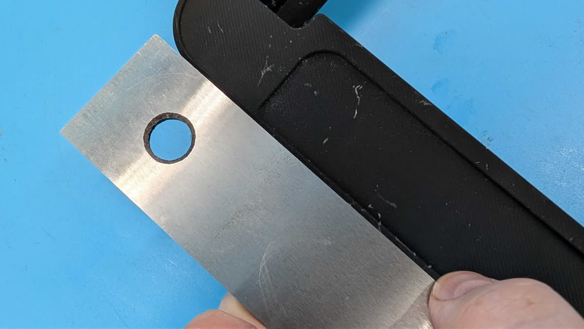
Edge of the part printed in the recommended orientation with no warp, shown with a machining parallel for reference.
|