
Low-Volume Rapid Thermoforming With 3D Printed Molds
Whether you are looking to design functional prototypes with end-use materials, fabricate parts during pilot production, or manufacture end-use parts, 3D printed rapid tooling is a cost-effective and quick way to produce parts.
This white paper provides methods and guidelines, including recommendations and molding conditions for forming thermoplastics with 3D printed molding. Learn how on-demand custom tooling adds flexibility to manufacturing processes, accelerating product development and bringing innovative products to market.
Low-Volume Rapid Thermoforming With 3D Printed Molds
Download as PDFWhether you are looking to design functional prototypes with end-use materials, fabricate parts during pilot production, or manufacture end-use parts, 3D printed rapid tooling is a cost-effective and quick way to produce parts.
This white paper provides methods and guidelines, including recommendations and molding conditions for forming thermoplastics with 3D printed molding. Learn how on-demand custom tooling adds flexibility to manufacturing processes, accelerating product development and bringing innovative products to market.
Introduction
Thermoforming Processes
Thermoforming is a set of manufacturing processes that heat and form sheets of plastics onto a tool. It is used extensively to produce disposable food and medical packaging, consumer goods and appliances, but also for heavy-duty applications such as automotive components and train interior parts. Thermoforming processes are versatile: depending on the technique, they can be employed for single products or batch production with low to moderate unit costs.
There are three main thermoforming methods:
-
Vacuum forming is the simplest, least expensive, and most commonly used of these techniques. A sheet of plastic is heated and then pulled around a single mold using suction — typical vacuum draws are around 0.9 bar (14 PSI). It is ideal for parts that only need to be precisely formed on one side, such as contoured packaging for food or electronics.
-
Pressure forming is the second most popular technique. The heated sheet of plastic is forced into the tool with pressure — typical pressures are around 6.9 bar (100 PSI). Higher pressures can form complex and intricate details, with a surface finish similar to injection molded parts. Pressure forming and vacuum forming are both suitable for shallow geometries.
-
Mechanical forming is a plug-assisted process involving a two-part tool that is ideal for deep profile parts. Negative and positive molds are pressed together to form the heated plastic sheet. Dimensional tolerance and surface finish quality are superior to other processes, however, it is the most complicated and expensive method.
The most prevalent thermoforming materials are common thermoplastics such as ABS, PET (including PETG), high impact polystyrene (HIPS), polycarbonate (PC), polypropylene (PP), and polyethylene (PE). There are two types of sheets available: thin-gauge (thickness under 3 mm) and thick gauge (thickness over 3 mm). Easier to process, thin gauge sheets dominate the market and are largely used for packaging, while thick gauge sheets are formed for heavy-duty applications such as rigid enclosures.
Thermoforming Tooling
Traditionally, thermoforming tools—also referred to as molds, forms, or bucks—are fabricated by CNC machined metal for large production, or wood or composite board (foam or fiberglass) for smaller batches. These processes all require expensive equipment and labor for CAM settings and machine operation. Outsourcing the mold comes with weeks of lead time and can cost thousands of dollars. As a result, producing limited quantities of thermoformed parts—for prototypes or low-volume batches—is usually not a viable option.
Desktop 3D printing is a powerful solution to fabricate tools rapidly and at a low cost. It requires very limited equipment, saving CNC time and skilled operators for other high-value tasks in the meantime. With in-house 3D printing, manufacturers and product designers can introduce rapid tooling into the product development process to validate design and material choices prior to transitioning to mass production. They can iterate quickly, accelerate product development and bring better products to market.
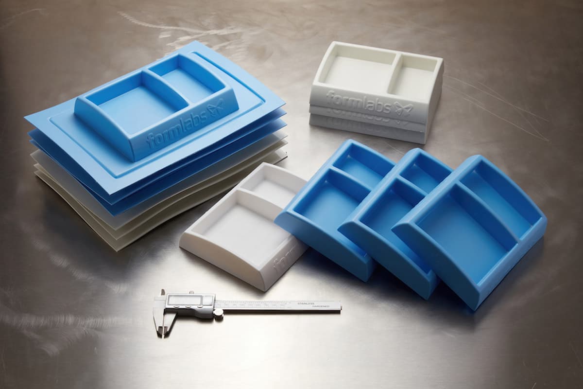
Stereolithography (SLA) 3D printing technology is a great choice for molding. It is characterized by a smooth surface finish and high precision that the tool will transfer to the final part and that also facilitates demolding. Molds produced by SLA 3D printers are chemically bonded such that they are fully dense and isotropic, producing functional molds at a quality not possible with other common 3D printing technologies, such as fused deposition modeling (FDM). SLA 3D printing also offers unmatched design freedom to create complex and intricate molds.
Desktop SLA printers, such as the Form 4, can seamlessly be integrated into any workflow as they are easy to implement, operate, and maintain. While being compact enough for an office, the large format 3D printer Form 4L enables the fabrication of large-scale parts and molds. Additionally, Formlabs offers a wide range of engineering materials with mechanical and thermal properties that pair well with tool manufacture.
This white paper will give a general overview of the workflow, design guidelines, and best practices for 3D printing thermoforming molds, focusing on vacuum forming and pressure forming. Then, it will go into detail by covering three case studies from the plastic research center IPC, the product development firm Glassboard, and the machinery manufacturer Formech, that each explore the potential of 3D printed rapid tooling.
Method
Process Workflow
Thermoforming with 3D printed molds:
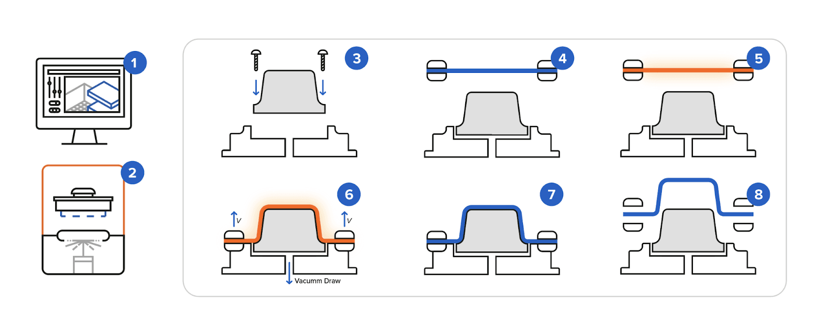
(1) Mold design (2) Mold 3D printing (3) Mold assembly (4) Sheet clamping (5) Heating (6) Forming (7) Cooling (8) Demolding and trimming
Design Guidelines
When designing a thermoforming tool for 3D printing, it is good practice to adhere to the rules of design for additive manufacturing as well as the general rules for thermoforming mold design. 3D printed molds can accommodate the same features as metal molds and expand design freedom with even more intricate mold geometries. Here are some helpful recommendations from industry experts, specific to polymer printed tools for vacuum forming (and can also be applied to pressure forming).
To improve the vacuum and the surface finish:
-
Hollow the mold to circulate the air and reduce the volume of resin. This will save material cost and printing time, while optimizing the vacuum. Formlabs recommends 1-2 mm minimum wall thickness.
-
Include air vents respective to the suggested diameter associated with your sheet thickness. 3D printing allows you to incorporate particularly small vent features on the outside of the mold, in almost any location without further effort. This permits a more complete draw, with an even distribution of the vacuum across the surfaces, improving part quality. Air vents as small as 0.5 mm in diameter can be printed easily with Grey Resin. However, with Rigid 10K Resin and Fast Model Resin, holes smaller than 1 mm in diameter might need to be pierced at the surface.
-
Avoid sharp edges. Increasing the radius for corners in the draw direction will help reduce the chances of material webbing.
-
Avoid supports on molding surfaces.
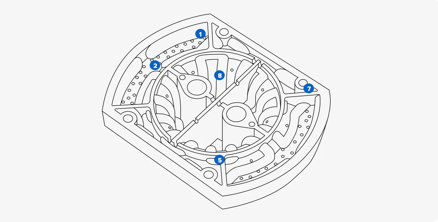
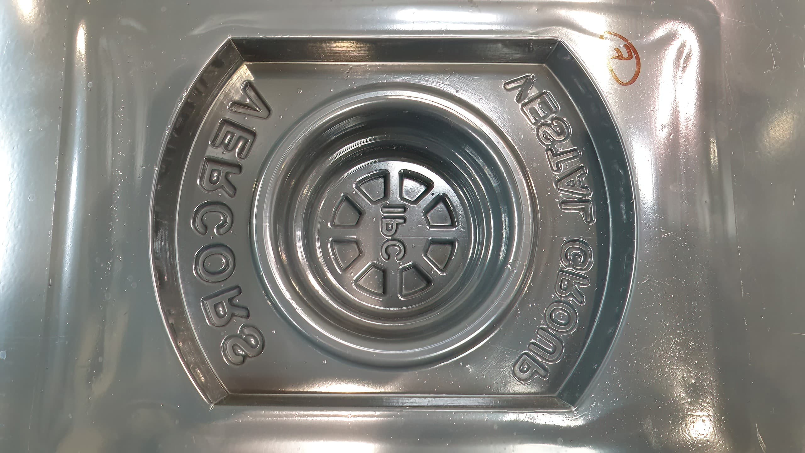
Back of the tool pictured.
To extend the lifetime of the tool:
-
Add a network of ribs following the topology of the part to reinforce the mechanical support and prevent warping. Include notches on the ribs to circulate the air.
-
Increase draft angles to facilitate the demolding (2-3° minimum).
-
Build assembly features in order to fix the tool to the baseboard of the thermoformer. Tapped holes can be directly integrated into the model. In case of dimensional variations, they can be groomed with a drill after printing. Plan enough assembly components to prevent breakage during the ejection of the part. Alternatively, flat strips can be added at the base of the model in order to fix the tool with double-sided foam tape. However, the foam can compress under heat during the process and restrict the vacuum flow.
-
For large molds and higher volumes, include cooling channels to regulate the temperature of the tool.
-
If undercuts or other geometries that are difficult to demold can not be avoided: design the tool in multiple parts. Collapsing bucks can facilitate the part ejection and magnets can be added to hold parts together.
-
Incorporate a cutline into the CAD design of your tool for trimming the excess material after molding. It also helps to elevate your part during the vacuum forming process to mitigate errors at the machine level.
Choosing the Right 3D Printing Material
Thermoforming tooling should be able to withstand the assembly forces, forming forces (vacuum and pressure are considered in this report), temperatures, demolding forces, and any coolants or mold release agents that may be used. Formlabs offers a range of materials that meet these requirements and are capable of replacing aluminum molds for low-volume manufacturing.
The mechanical characteristics of SLA 3D printed tools decrease under high temperatures. However, as heat transfer occurs more slowly in plastic parts, high-temperature molding is achievable as long as the exposure time is short and the temperature of the mold remains relatively low. The choice of resin depends on technical and production requirements:
-
Choose Fast Model Resin if you only need to form one to five units and wish to iterate on your design quickly. Fast Model Resin prints at a lower resolution than Formlabs' standard materials, but up to four times faster. It is ideal for large parts, simple designs, initial prototypes, and rapid iterations.
-
Choose Grey Resin if you only need to form one to five units with high surface finish quality and level of detail. Typically, thermoforming is not a highly accurate process; in most cases the surface finish and level of details given by Fast Model Resin are sufficient. However, Grey Resin leads to better accuracy, consistency, and simpler support removal, and is preferred for smaller parts when print speed is not a concern. If you wish to fabricate multiple parts with a mold printed in Grey Resin or Fast Model Resin, you should dedicate sufficient time for mold cooling (8 to 10 minutes depending on the part and material)
-
Choose Rigid 10K Resin if the tool is exposed to more challenging forming conditions. It is an industrial-grade, highly glass-filled material capable of forming limited series of dozens of parts with cycle times close to production. Rigid 10K Resin has an HDT of 218 °C @ 0.45 MPa and a tensile modulus of 10,000 MPa, making it a strong, extremely stiff, and thermally stable molding material that will maintain its shape under pressure and temperature to produce accurate parts.
The table below offers a summary of our recommendations. More dots indicate better performance under certain conditions:
| Criteria | Fast Model Resin | Grey Resin | Rigid 10K Resin |
|---|---|---|---|
| Shorter Print Time | ★★★ | ★ | ★ |
| Lower Material Costs | ★★★ | ★★★ | ★ |
| Facilitate Support Removal | ★ | ★★★ | ★★ |
| Improve Surface Finish | ★ | ★★★ | ★★ |
| Increase Sheet Thickness | ★ | ★ | ★★★ |
| Increase Forming Time | ★ | ★ | ★★★ |
| Decrease Cooling Time | ★ | ★ | ★★★ |
| Increase Number of Cycles | ★ | ★ | ★★★ |
Workflow Guidelines
Mold Assembly
Once the tools are printed, wash the air vents and cooling channels carefully with IPA following Formlabs instructions and dry the part using an air gun to remove any resin excess that could harden inside the holes. Post-cure the prints according to the Formlabs guidelines. If there are some dimensional variations, groom the tool with sanding, desktop milling, or drilling to meet critical dimensions. If you are using Rigid 10K Resin, wipe the part with mineral oil to remove any excess powder from the surface. Depending on the machinery, the printed tool can be threaded to a metal plate that will be installed on the thermoformer.
Equipment
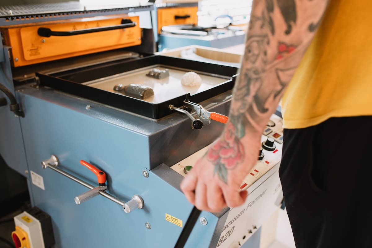
If you are looking for accessible equipment to fabricate simple geometry prototypes with thin sheets, such as packaging, desktop vacuum formers are affordable and easy-to-use solutions, like the Formech 450DT, or models from Mayku, and Smartform. For items with a deeper profile and thicker gauge, you will need the stronger draw and even heating from an industrial machine such as the Formech 508FS, GN, Ridat, or Belovac products. The plastic formed will have an influence on the choice of the equipment. Materials such as polycarbonate (PC) are more challenging to thermoform than other plastics, involving high temperatures and vacuum or pressure forces as well as thermal post-treatment.
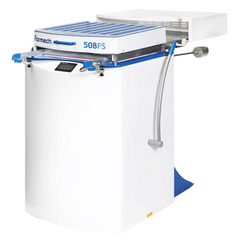
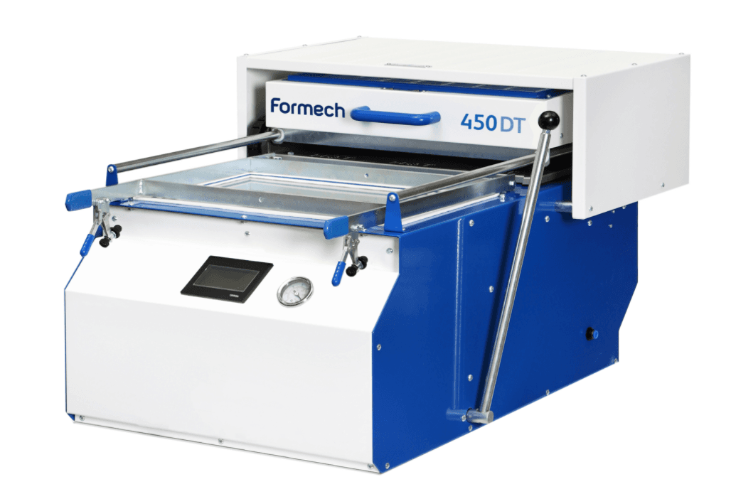
The Formech 450DT (left) and the Formech 508FS (right).
Material
A broad range of thermoplastics can be thermoformed with 3D printed tools. In this white paper, we report on molding conditions with HIPS, ABS, PC, PETG, PE, and PP. Follow the data sheet instructions from the plastic you are using in order to set the temperature, thermal pretreatment, and other protocols. Mold release is widely available to facilitate the demolding, and silicone mold releases, such as Slide or Sprayon products, are compatible with Formlabs Grey Resin, Fast Model Resin, and Rigid 10K Resin. Use good cutoff tools to trim your final part; tin snips for thin sheets and Dremel cutoff wheels for over 1.5 mm thick sheets.
Case Studies
In this section, we will go through the case studies from IPC, Glassboard, and Formech. Read on to see how 3D printed thermoforming molds were used on both benchtop and industrial machines to efficiently and affordably produce dozens of functional prototypes, parts for pilot production, and end-use parts.
IPC Thermoformed Thick PS and ABS Sheets for Automotive Parts
Background
IPC is the Industrial Technical Center whose expertise is dedicated to plastic and composite innovation in France. IPC develops new means to support all businesses, in particular small and medium-sized companies. The center works closely with European key scientific players in order to support companies on R&D, innovation, technology, and skills transfer, regardless of the process used. IPC teams help manufacturers drive innovation by performing studies, establishing protocols, establishing feasibility, and assisting with technology transfer. They have been exploring the potential of rapid tooling with 3D printing for years, in particular, the viability of 3D printed injection molds for low-volume production.
Recently, IPC conducted a research project dedicated to 3D printed tooling for vacuum forming in partnership with the VESTAL Group. They conducted feasibility and longevity tests on 3D printed torture-test tools that present some common thermoforming challenges. We summarize their experiments and findings in this report.
Objectives
VESTAL Group is a leading supplier of thermoformed parts and solutions, specializing in very large units for the medical, railway, leisure vehicle, and light, medium, and heavy commercial vehicle sectors. They answer a high demand for prototypes, low and medium volumes of end-use production. The purpose of this study is to achieve prototyping tools capable of fabricating low to medium-sized batches in molding conditions close to production, with short lead time and reduced costs.
Choosing the 3D Printing Technology
IPC compared four different 3D printing technologies: SLA, DLP, SLS, and FDM. The properties considered for thermoforming tools are roughness and thermal resistance. They compared the materials’ HDT and measured the roughness of benchmark parts.
| DLP Resin | Rigid 10K Resin | FDM - ULTEM 9085 |
|---|---|---|
| 120-125 °C (0.46MPa) | 163-218 °C (0.46MPa) | 180 °C (0.46MPa) |
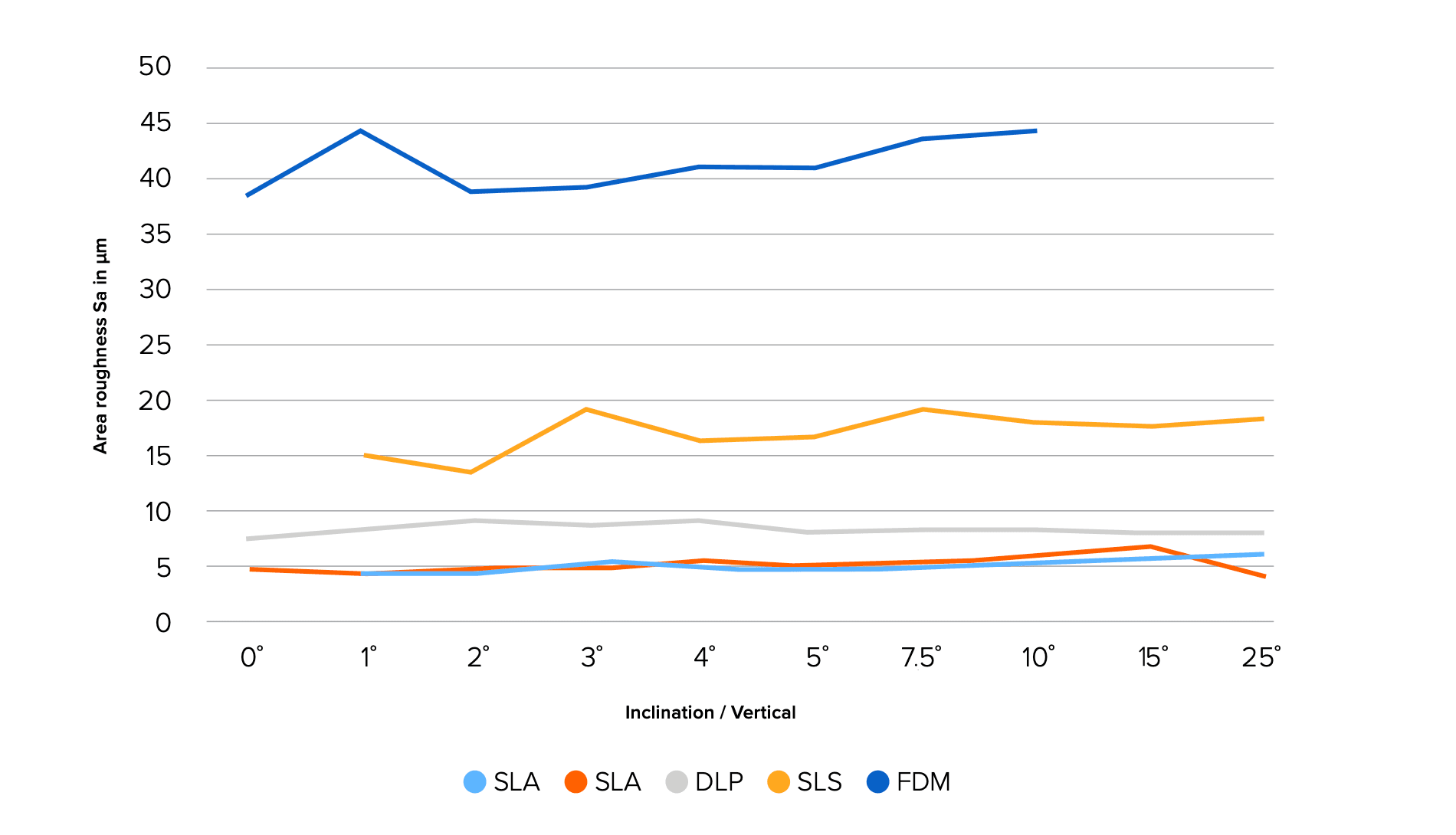
Roughness measured on benchmarks.
This paper exhibits the experiments run with Formlabs’ solution. The comprehensive study including a technologies comparison is available upon request from IPC.
Mold Design
Part Description
The torture-test part was designed respecting the following specifications:
-
Presence of embossed and engraved details.
-
General draft angle at 3°.
-
Presence of zone without draft angle.
-
Presence of writing at 2 mm thickness embossed and engraved.
-
Presence of areas with sharp edges.
-
Presence of areas with a radius of 5 mm.
-
Vacuum holes diameter from 0.8 mm to 1.2 mm maximum.
-
Part dimensions at 60 x 130 x 168 mm.
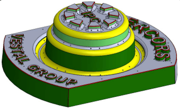
CAD design of the Torture part 1, with embossed details. Legend: 0° draft angle in light green, 3° draft angle in dark green, 5 mm radius in yellow, sharp edges in red. A similar part was created with engraved details, leading to very similar results. For the sake of clarity, we focus on the one with embossed details in this article.
Design Guidelines
The printed tool should be able to withstand two types of stresses:
-
The vacuum force used to form the part (up to -0.8 bar).
-
The ejection of the part. This varies according to the processed material, its thickness, the roughness of the buck, and the adhesion between the material and the mold.
To face these constraints, the design includes:
-
Rigidification by a network of circular ribs following the topology of the part.
-
Fixation on the machine by four M8 threads. The holes were printed and then groomed with a drill to compensate for dimensional variations.
-
Vacuum through smooth holes of 1 mm diameter (some holes cross a rib on both sides).
-
Creation of notches between the chambers to circulate the air.
Other design best practices:
-
Avoid supports on the molding surfaces for a better surface finish.
-
Hollow the tool in order to reduce the volume of resin. This saves material cost and printing time, and creates a better air circulation inside the part to optimize the vacuum.
Adding a Thermal Regulation System and Fixtures for Assembly
IPC iterated on the design, running feasibility tests to optimize the tooling. They fabricated three different molds:
-
Torture-test part V1. As described in the previous section.
An initial test on this mold highlights the need for a cooling method. After only two cycles, the temperature of the 3D printed tool was too high, decreasing its mechanical properties. It broke at the location of the machine’s fixtures and stayed stuck to the formed part.
-
Torture-test part V2 with regulation. IPC incorporated cooling channels to the initial model in order to regulate its temperature while maintaining low cooling times:
-
The water inlet and outlet are 8mm diameters, positioned at the center of the part.
-
The water inlet and outlet are screwed to the tool with 3/8 BSP thread.
-
In order to reduce complexity, the network was divided into four channels of 4 mm in diameter, at a 5mm distance from each other.
-
The air vents are 1.2mm in diameter.
-
A second test showed a stable mold temperature. However, a leak was recorded during ejection at the entry of the water channels. The assembly needed improvements.
-
Torture-test part V3 with regulation and fixation. IPC consolidated the design with two additional fixtures closer to the joints in order to tighten the assembly and avoid water leaks.
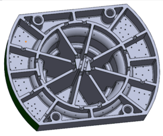
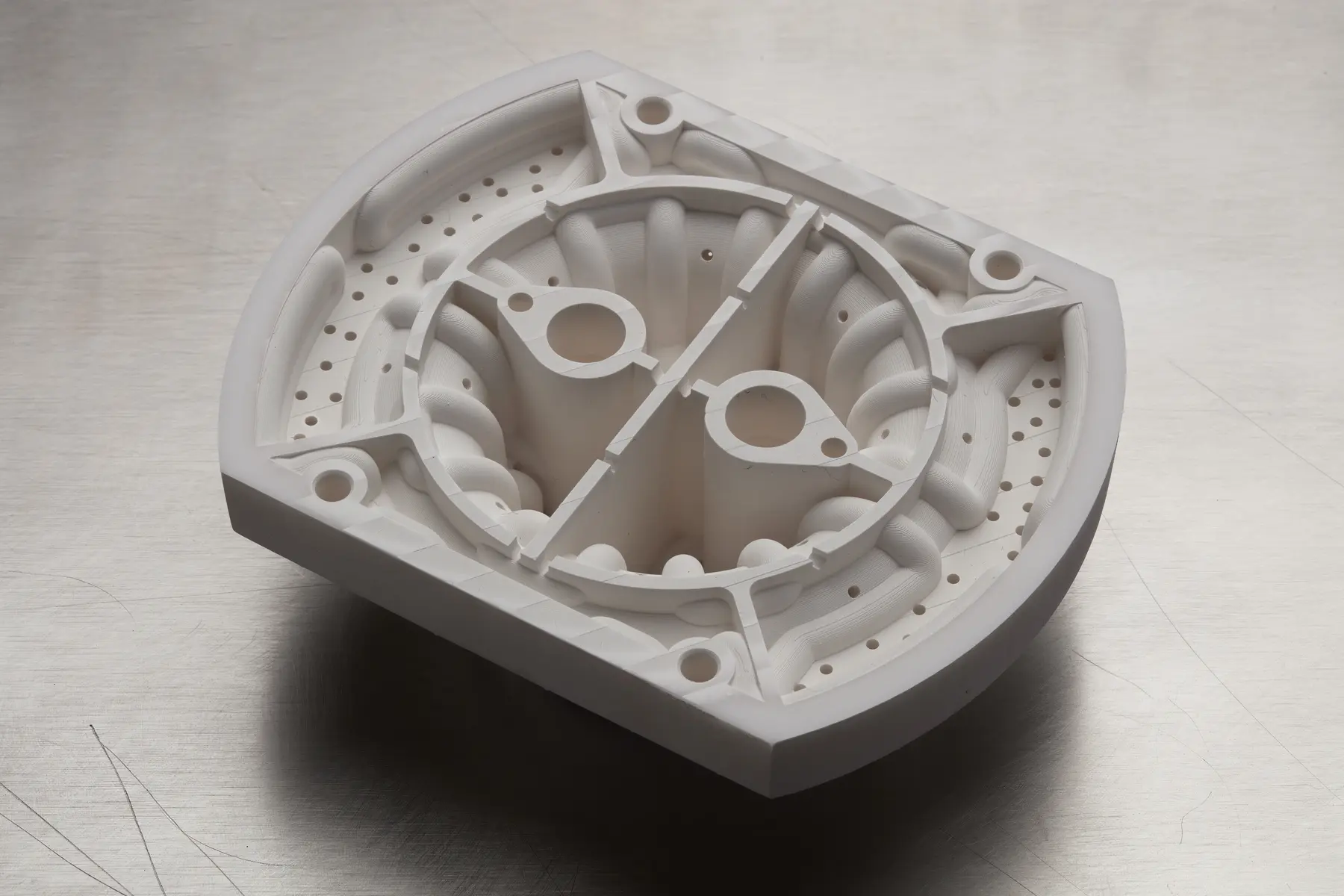
CAD design of the back side of Torture parts V1 and V3 with cooling channels.
IPC spent about four hours designing this part in CAD and about eight hours introducing the regulation. The amount of time can vary depending on the expertise of the designer and is similar to the CAD time required for a traditional tool.
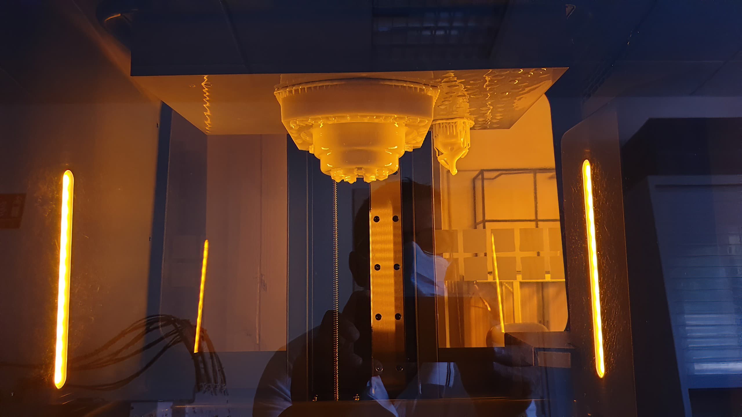
Mold 3D Printing
The molds were 3D printed on a Form Series SLA printer with Rigid 10K Resin at 100 microns layer height. They were subsequently washed in IPA twice for 10 minutes. The cooling channels were controlled using a thermographic camera in order to ensure the absence of resin inside. The parts were then post-cured for 60 minutes at 70 °C. The fixturing M8 threads were tapped.
| Step | Machine Time (h) | Labor Time (h) | Step Done By |
|---|---|---|---|
| Print Preparation | 0 | 0.75 |
D+0.5 |
| 10 | 0.25 |
D+1 |
|
| IPA Wash | 0 | 0.75 | D+1.5 |
| Control Channels for Obstruction | 0 | 0.5 | D+2 |
| Post-Cure | 1 | 0.0 | D+2.5 |
| Tapping | 0 | 0.25 | D+3 |
|
Control Dimensional Variation With Scanning Metrology |
0 | 1 | D+3.5 |
| Total Time Needed | 11 | 3.5 | 3.5 days |
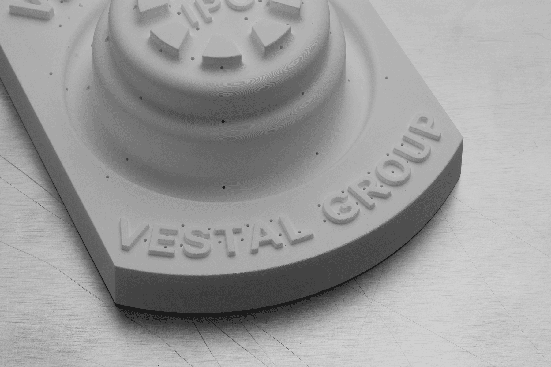
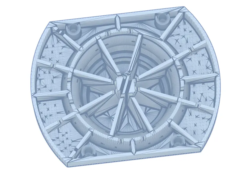
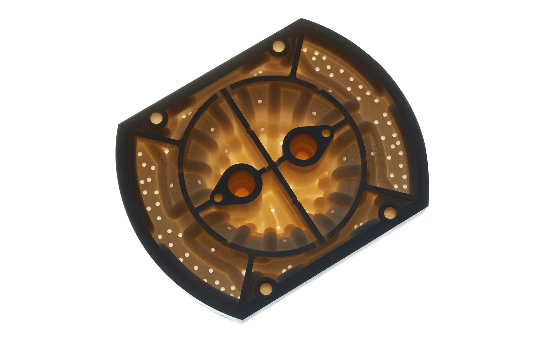
Front (left) and back (right) sides of the 3D printed Torture-test part V3.
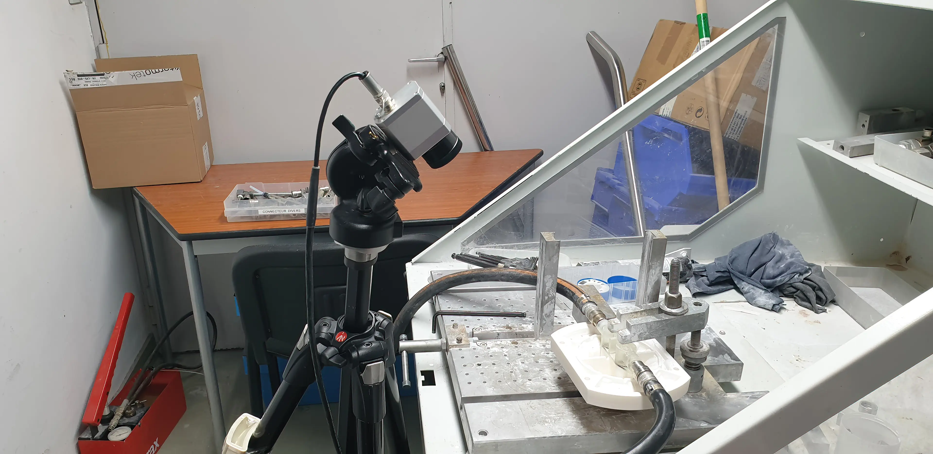
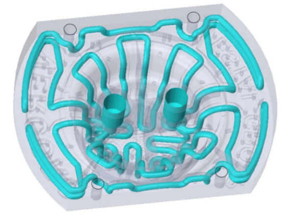
IPC's setup to control the cooling channels for obstruction using a thermographic camera.
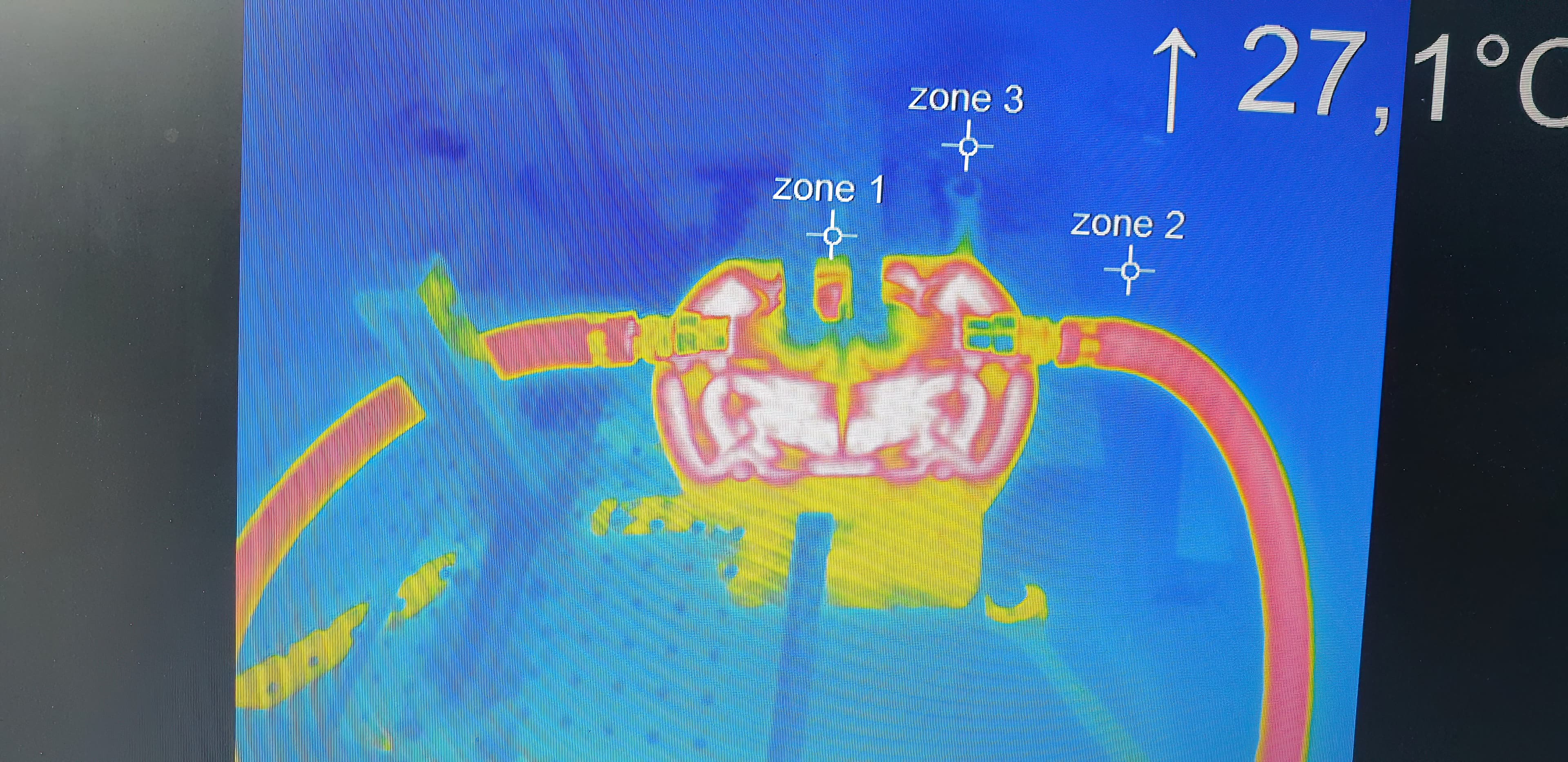
Thermal image from the 3D printed torture-test part with regulation. The fluid (at 40°C temperature) circulates easily through the cooling channels, showing no obstruction. The flow rate measured is 11.4 l/min at a 2.4 bar pressure.
Molding
The process conditions were set to approach production conditions:
-
Material: PS sheet of 3 mm thickness
-
Cycle time: 200 seconds. It was calculated as a 25% longer cycle time compared to a traditional aluminum tool.
-
Thermoforming temperature: 170 °C
-
Thermoformer: BERG M7
-
The tool was connected to the general water supply at 20 °C.
-
The tool was fixed on a plate that was installed on the machine.
-
A thermographic camera was controlling the temperature of the tooling.
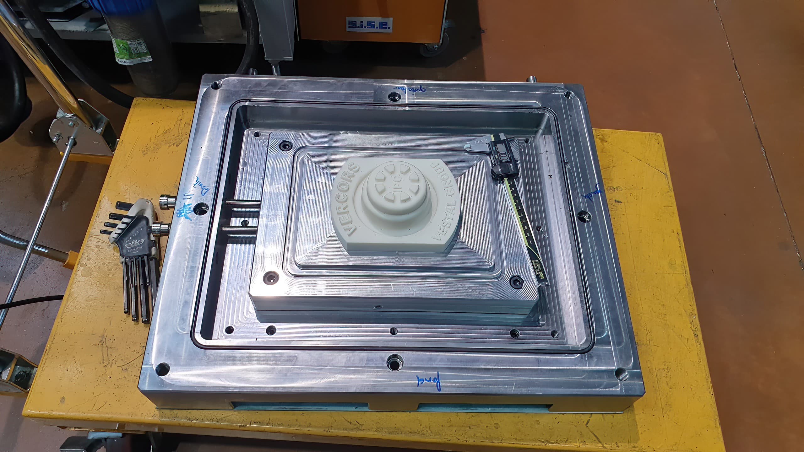
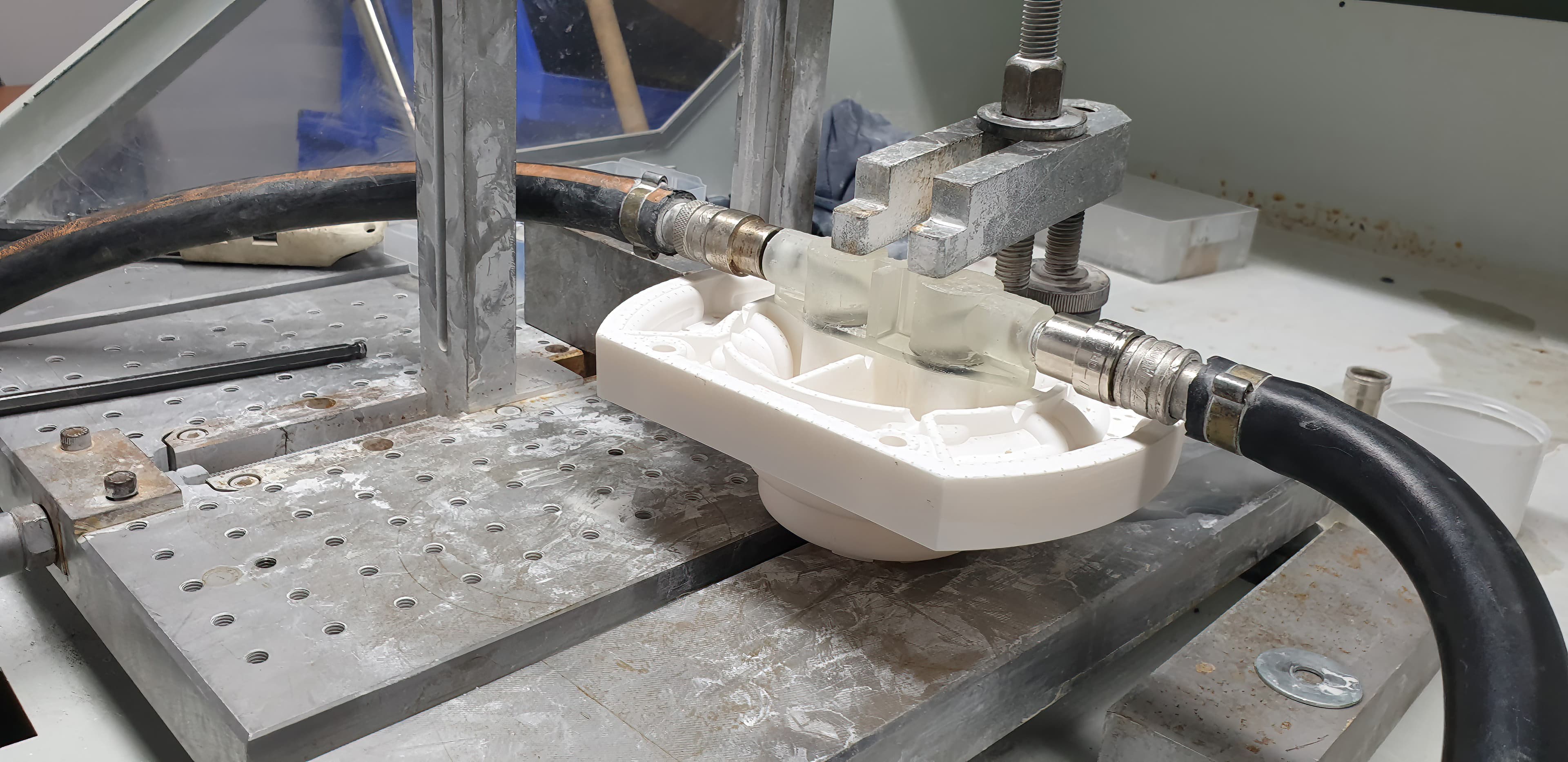
The 3D printed tool fixed on a steel XC48 plate to be installed on the machine (left) and the plate ready for the first cycle (right).
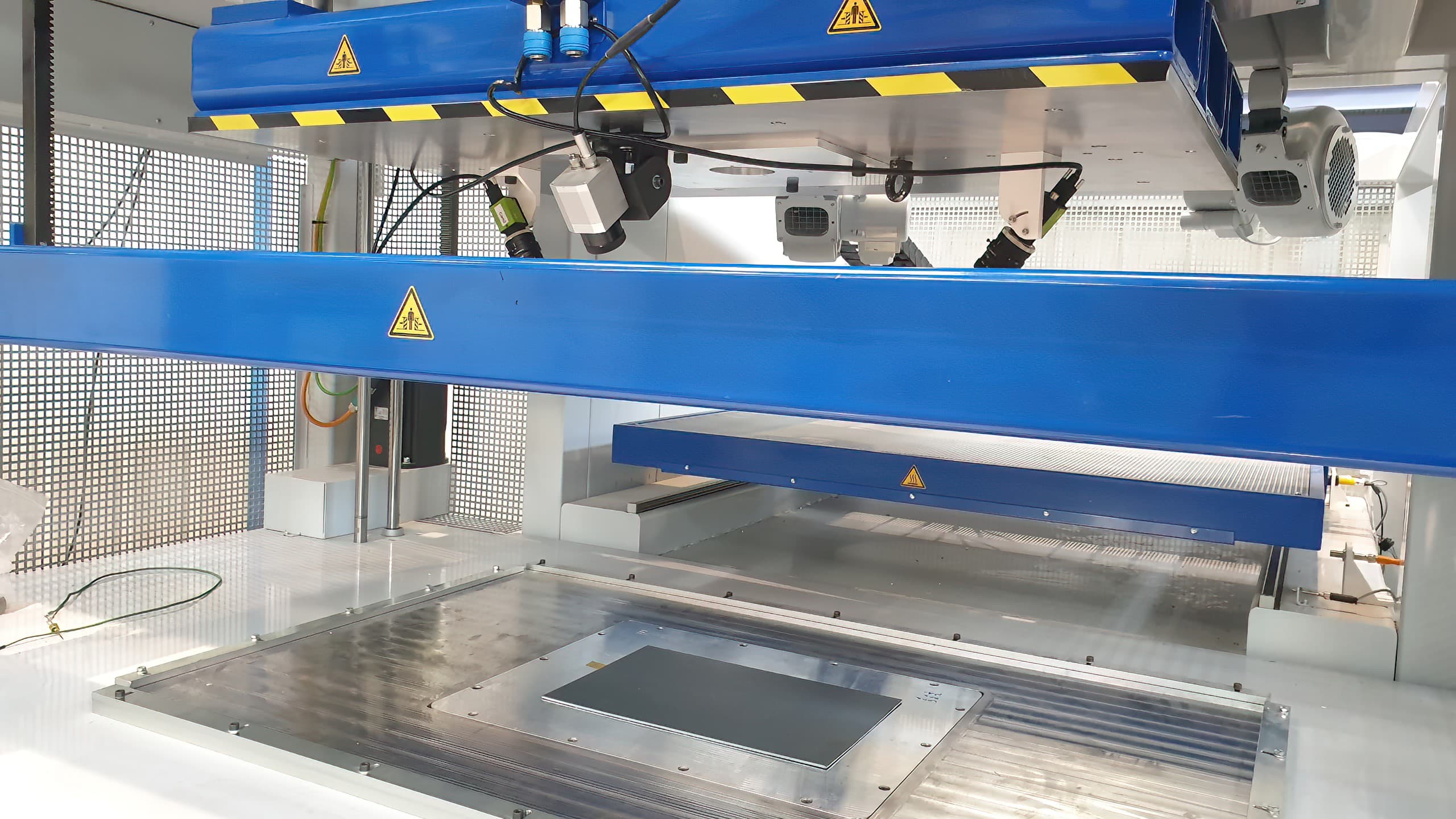
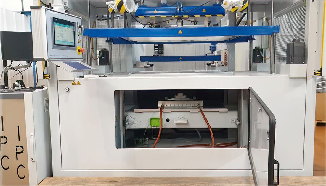
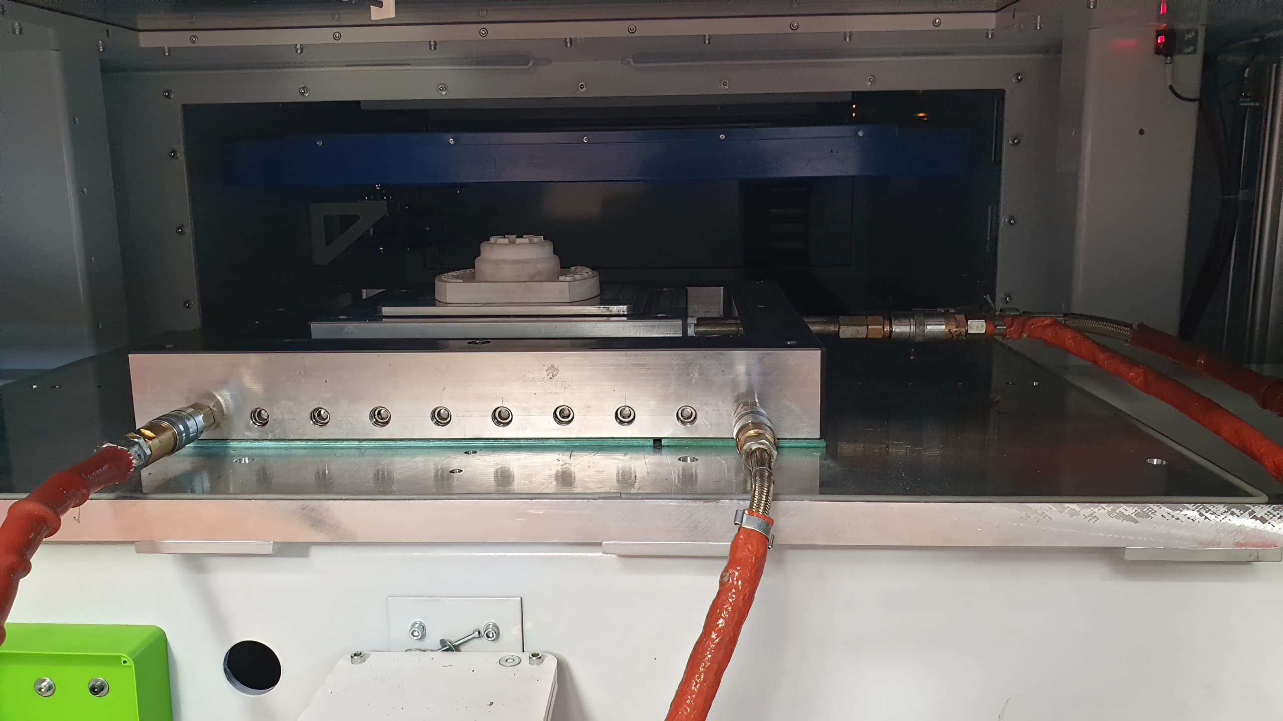
The Thermoformer BERG M7.
Results
The printed tools had very good roughness.
Dimensional variations from theoretical values were observed; negative on the Z axis and positive on the build platform. There was a presence of warping on the prints, however, the 1 mm diameter vent holes were well opened.
The temperature of the buck was stable at 75 °C throughout the process thanks to the thermal regulation system. 200 seconds of cycle time was respected.
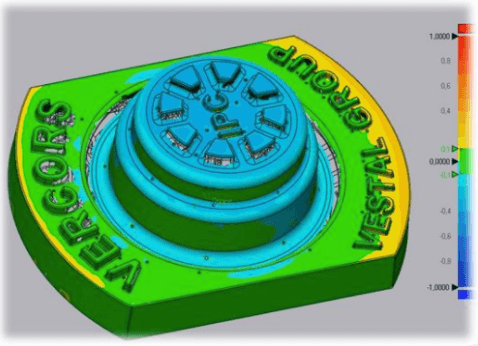
Scan of the tool 3D printed with Rigid 10K Resin. Dimensional variation around -0.2 mm.
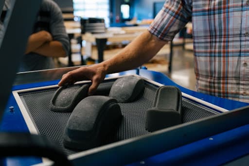
20 parts of 3 mm PS sheets were formed with one 3D printed buck, without tool degradation. IPC expects a printed mold to be capable of withstanding about 50 parts in these conditions. The quality of the formed parts was similar to the one achieved with traditional tooling; the surface finish was smooth without shrinkage or marking from the printed mold. The formed parts could be polished using emery cloth if necessary. ABS sheets were tested in the feasibility phase: from the similar behavior and material properties, IPC speculates these results are valid for thick ABS sheets.
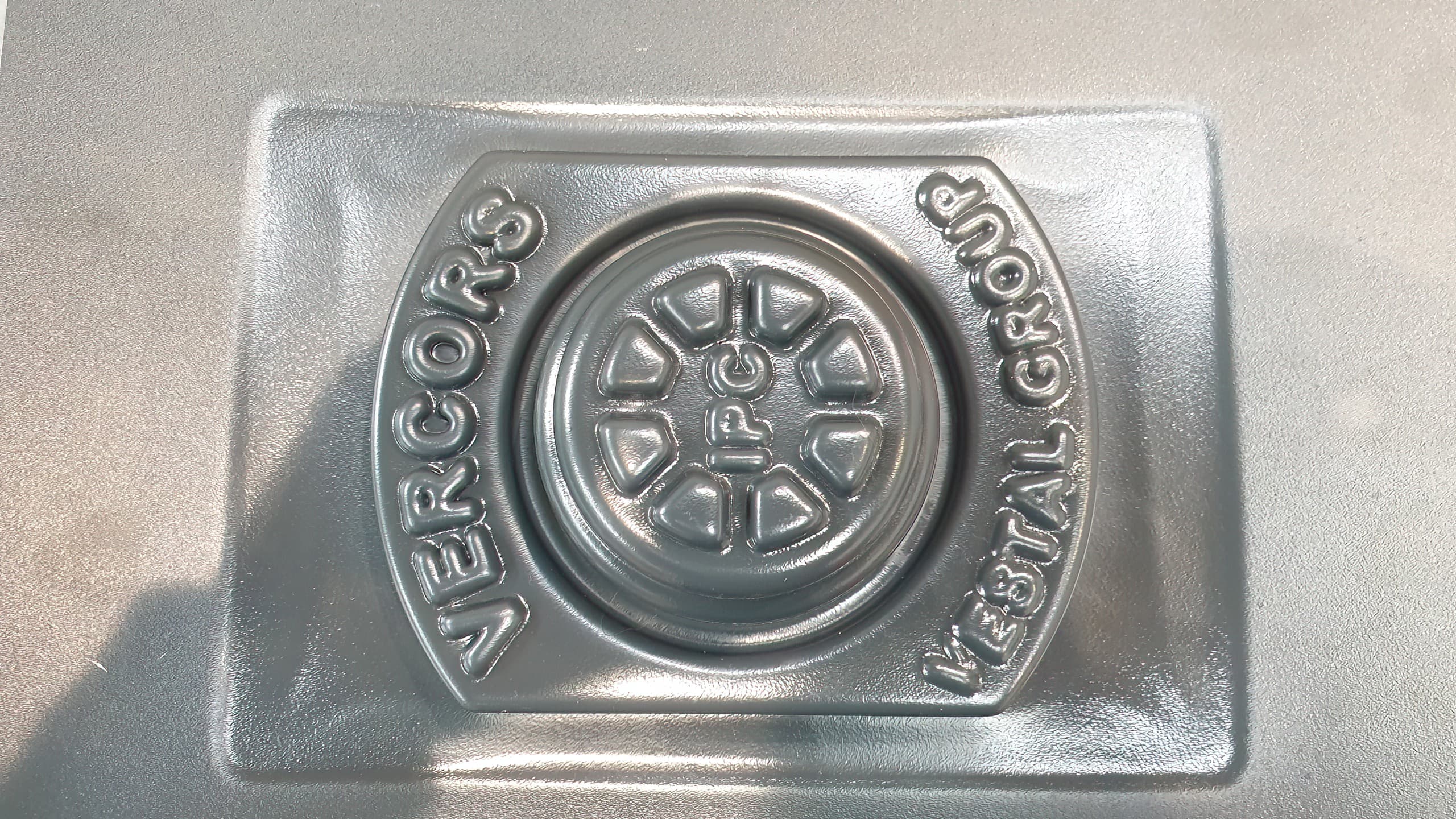
Thermoformed PS sheet 3 mm thickness, front (left) and back (right) sides.
Cost Analysis
The mold was available in 3.5 days, requiring 11 hours of machine time and 3.5 hours of labor. With a 50€/h rate, the labor cost was 175€. They used 387 mL of resin at the price of 249€/L, leading to 97€ in resin cost.
| Material Cost (€) | Labor Time (h) |
Total Cost (€) |
Lead Time (days) | |
|---|---|---|---|---|
| Outsourced to a Prototypist | 520 | 1 | 570 | 21 |
|
Outsourced Aluminum Tool |
710 | 1 | 760 | 21 |
| Outsourced DLP | 459 | 3 | 609 | 7 |
| Outsourced FDM |
480-743 |
3 | 630-893 | 7 |
| FDM In-house | 132 | 5 | 382 | 3.5 |
|
Formlabs SLA In-house |
97 | 3.5 | 272 | 3.5 |
Conclusions
This study demonstrated that molds 3D printed with Formlabs Rigid 10K Resin are able to thermoform thick PS sheets, for up to 20 to 50 cycles. Incorporating cooling channels in the mold design increases the mold longevity while maintaining a reasonable cycle time for low to medium production. Lead times are 3 to 7 times shorter than with traditional tooling, and costs are cut at least in half.
The quality of the molded parts is similar to the one obtained with aluminum tooling, however dimensional accuracy was not considered in the study. IPC recommends limiting the part size to the A4 (210 x 297mm) format in order to limit dimensional variations.
These results suggest that similar or better outcomes will be achieved with thinner sheets as well as for materials with characteristics inferior to those of ABS and PS. However, for sheets with stronger characteristics, such as PC, supplementary tests need to be performed.
Glassboard Thermoformed Thick PC Sheets for Consumer Goods Parts
Background
Glassboard is a product development firm helping ambitious companies design, develop, prototype, and introduce meaningful products to market. To better serve their clients, they use 3D printing across the entire product development cycle: from early prototypes directly printed, to pre-production parts and limited series with 3D printed tooling for injection molding, thermoforming, and silicone casting. The team guided us through the workflow they’ve used to vacuum form functional prototypes in polycarbonate (PC) from 3D printed molds.
Mold Design
Glassboard shared two of their latest projects: a test puck and a helmet. The molds are hollow, with cross members inside the parts to increase strength and avoid breakage of the mold under vacuum forming. The molding surfaces consist of small air holes of 1.5 mm in diameter for the vacuum process. The test puck is a simple geometry with 0.5 mm to 0.8 mm wall thickness and draft angles of at least two degrees.
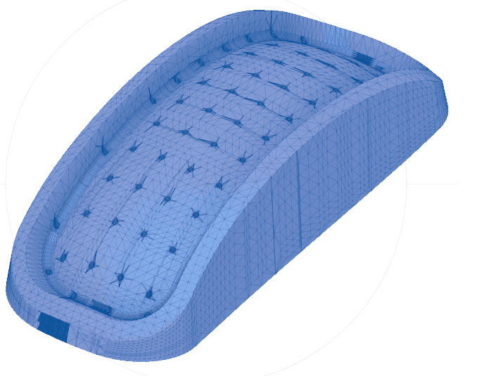
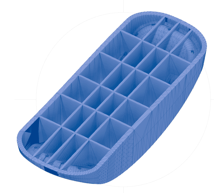
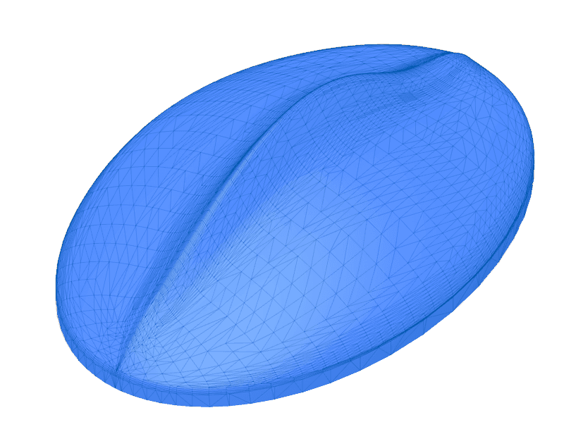
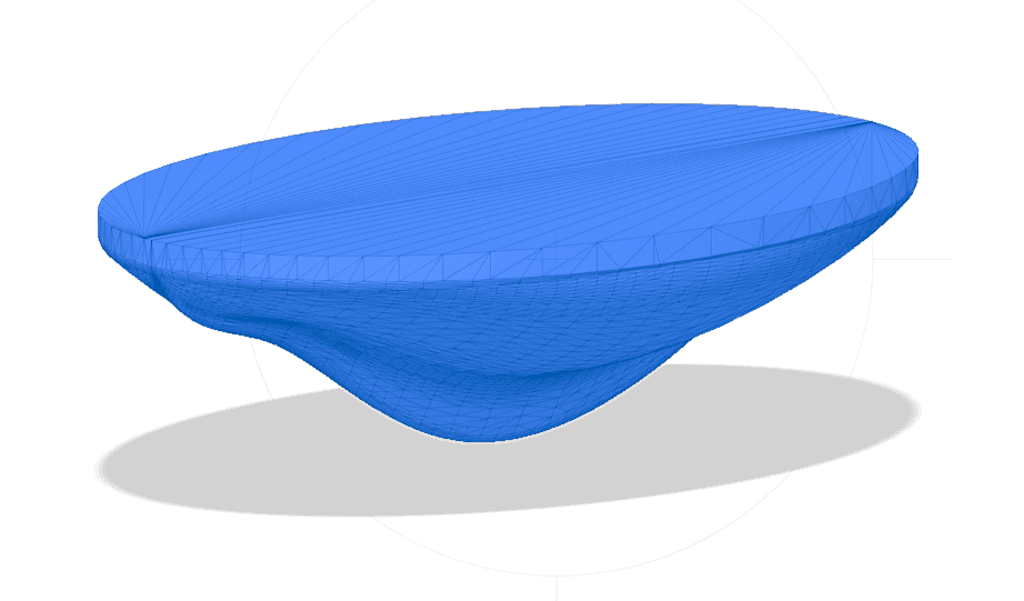
CAD model of the test puck front (left) and back (right).
The helmet has a 4 mm wall thickness and carries more challenging design features, in particular some undercut areas. The mold was designed in multiple parts in order to be able to separate it from the thermoformed product. The polycarbonate formed part is not easily flexible at this thickness, and reducing the surface of the undercut was not enough to demold the part. After a few design iterations, they landed on a five part mold geometry model: the bottom is one central core, which drops out first before pulling each individual slide of the mold out. Unfortunately, the parting lines were visible on the formed part. They used magnets inside the parts to hold the different pieces together and aligned while vacuum forming. Larger holes could be added to the core part to improve air circulation.
Mold 3D Printing
The tools were printed overnight with Formlabs Fast Model Resin on the Form Series at 200 microns layer height. Because of the large size of the helmet, the team chose to print with Fast Model Resin, the fastest-printing Formlabs resin, to increase the speed of iteration. After removing all the supports, they needed about 20 minutes of sanding and smoothing to finish the parts. It did not require any polishing or the use of mold release. For smaller parts, they usually print with the Grey Resin in order to reduce warping, in particular with long, thin sections.
“Once you’ve learned the process, tool design for 3D printing takes about 20 minutes for simple parts and less than a day for more complex geometries. It is an insanely fast process to go from part design to mold, and the next day, you get your final product. Then you can reuse that same mold to make multiple of these parts. It is a really powerful process,” said Grant Chapman, Glassboard VP of Operations.
Molding
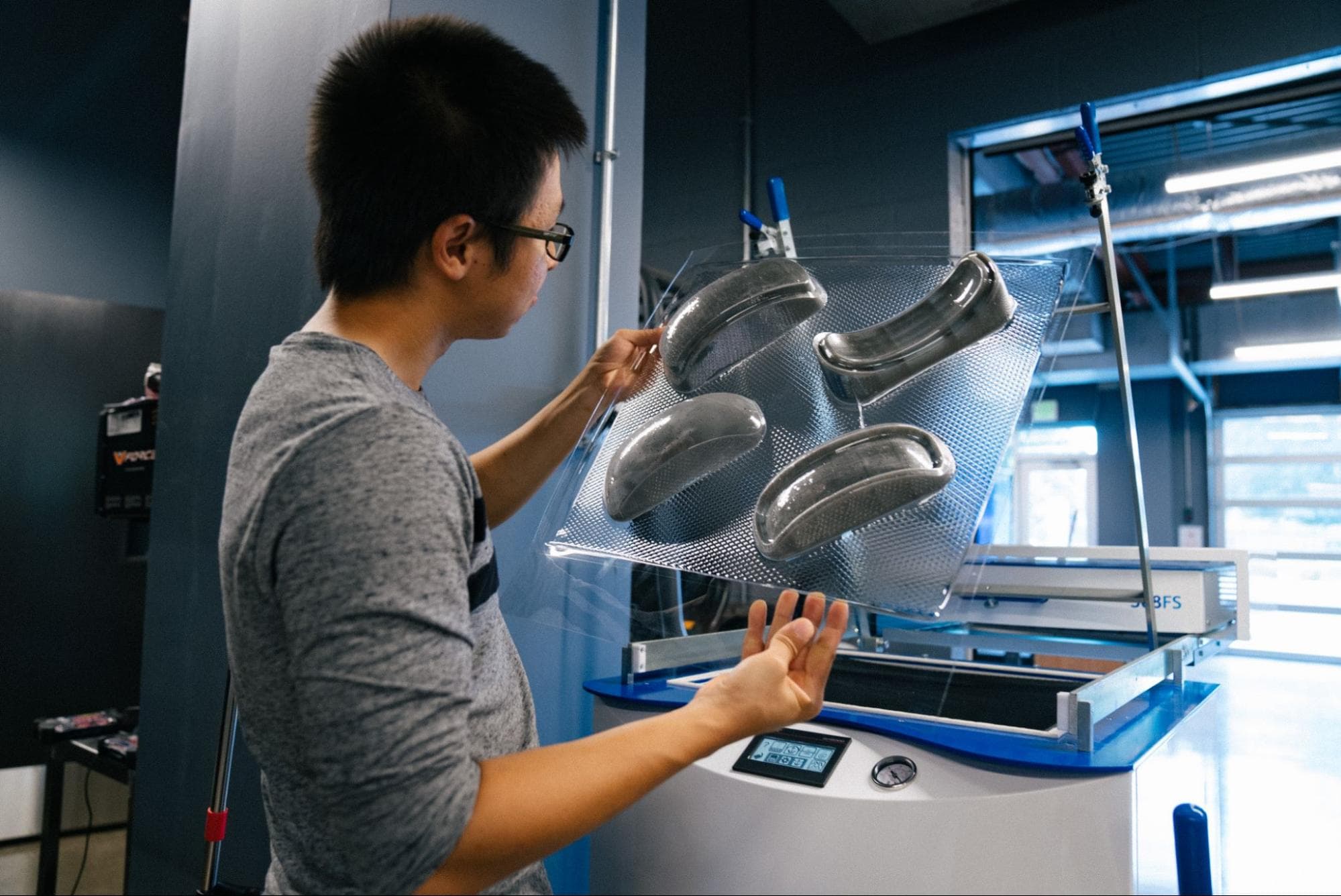
The team formed 3 mm thick PC sheets with the Formech 508FS thermoformer, resulting in a 1.5 mm thick thermoformed product. They used the standard molding conditions prescribed to vacuum form PC sheets. First, they baked the sheets in an oven for three days at 80-100 °C to remove moisture and get rid of the bubbles before forming. This step is specific to PC thermoforming — the thermal pretreatment of other thermoplastics, such as PETG can be much faster. The sheets were formed at a temperature ranging from 194 °C and 204 °C, at a pressure from 20 to 25 bar, with 8-10 minutes of cooling time.
Results
“I am blown away by how well the Fast Model Resin and Grey Resin hold up to the process, both from a force and a thermal perspective. That’s the surprising part. With affordable resin that prints very fast and quite accurately, you can have great parts with very little effort,” said Chapman.
The team fabricated 15 units of the test puck and two units of the helmet. They did not encounter any issue forming the sheets in the vacuum former: no melting or deformation was observed on the sheets, nor were the bucks cracked or burnt. They did not test the molds to failure, but believe they could withstand many more cycles if the eight to ten minutes of cooling time is respected. Cooling time could be reduced to two to three minutes by choosing a 3D printing material with higher thermal properties, such as Rigid 10K Resin.
Until now, the team was outsourcing tooling. By 3D printing it in-house with a Formlabs printer, they reduced the costs by 10x and the lead time from weeks to days. “We were not even vacuum forming as a business, and we were not proposing the option to our customers because it was not easy for us. Whereas now, it is so easy that it actually makes sense to fabricate looks-like and works-like prototypes with this process, even if the final product will be injection molded with a more intricate geometry. It is an unsung hero for how easy it is to process it,” said Chapman.
| Outsourced Tool | In-House 3D Printed Tool | |
|---|---|---|
| Equipment Needed | Thermoformer PC sheets |
Thermoformer Form 4L Fast Model Resin |
| Mold Production Time | 2-3 weeks | 1 day |
| Mold Production Cost | $5,000-$10,000 | < $400 |
Formech Thermoformed Thin Sheets of ABS and HIPS for Packaging
Background
Formech is a designer and manufacturer of vacuum forming machines, with 40 years of experience in delivering complete solutions, including consultancy, equipment, installation, and training throughout the globe. The machine range runs from manual machines right up to fully automatic machines. Formech is exploring innovative techniques to help their community be successful; gaining flexibility with on-demand tooling is one particular interest. The Formech team evaluated the viability of using 3D printed molds on their vacuum forming machinery and shared their results with us.
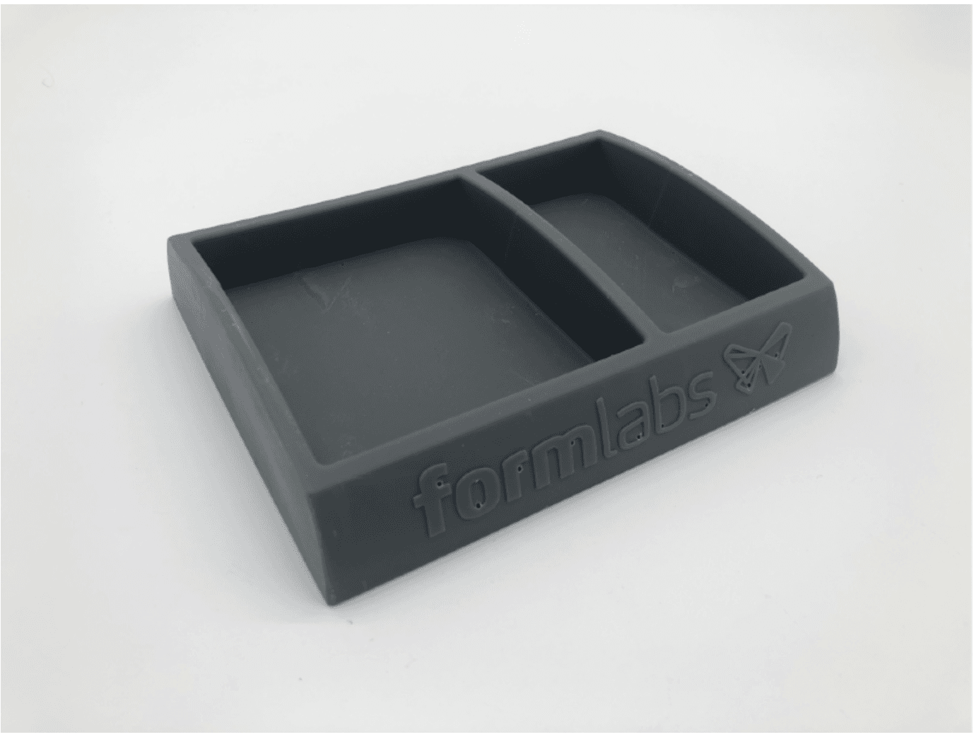
Mold Design
To reflect a common thermoformed item, Formech designed a pocket tray with the following specifications:
-
Part dimension at 200 mm x 160 mm x 42 mm.
-
Presence of embossed writing of 20 mm x 130 mm x 0.4 mm sizes, the logos followed the curvature of the tray face, and contained a small undercut.
-
6 mm wall thickness and 3° draft angles.
-
1 mm diameter vacuum holes.
-
The mold was drawn up hollow with a 3 mm wall thickness at the base to limit resin consumption. Additional ribs were placed on the underside for better mechanical support and improved airflow.
-
Presence of four flat stips on the underside in the grid area to fix the tool on the baseboard of the vacuum forming machine with double-sided foam tape or by the use of screws.
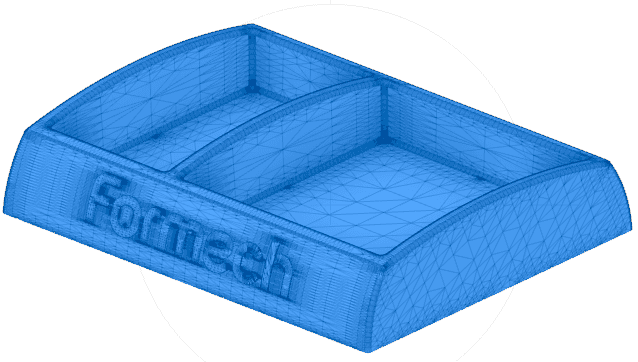
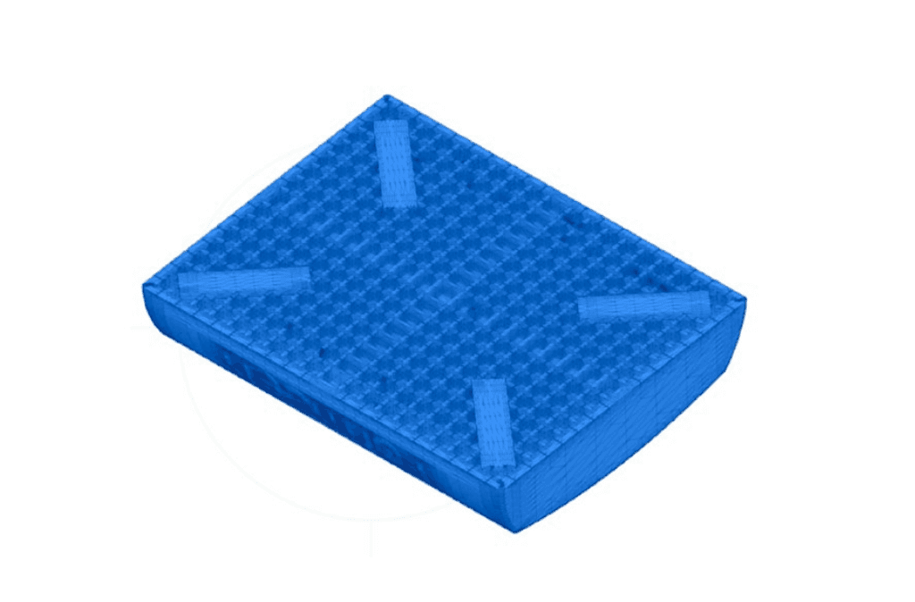
CAD model of the pocket tray front and back.
Mold 3D Printing
Three molds were 3D printed on the Form 4L printer with Grey Resin, Rigid 10K Resin, and High Temp Resin at 100 microns layer height. The prints were washed and post-cured following Formlabs’ instructions.
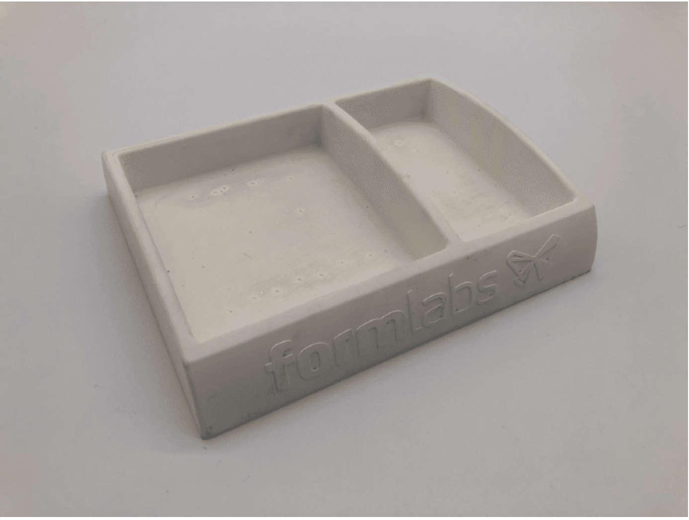
Molds 3D printed with Grey Resin (left) and Rigid 10K Resin (right).
Molding
The team formed the pocket tray with the following molding conditions:
-
Material: White ABS and light blue HIPS sheet at 1.5 mm thickness.
-
Cycle time: 2.5 minutes.
-
Thermoforming temperature: 180 °C.
-
Vacuum former: Formech 686 using a small reducing window to reduce plastic waste.
-
The tool was fixed to the baseboard with screws:
-
The Grey Resin tray was screwed down using twin thread wood screws at 3.5 mm diameter. 3.0 mm diameter pilot holes were used for the screws to grip sufficiently.
-
The molds printed with Rigid 10K Resin were drilled and tapped after printing using M5 machine screws, as the resin is less flexible and much more rigid than the Grey Resin.
-
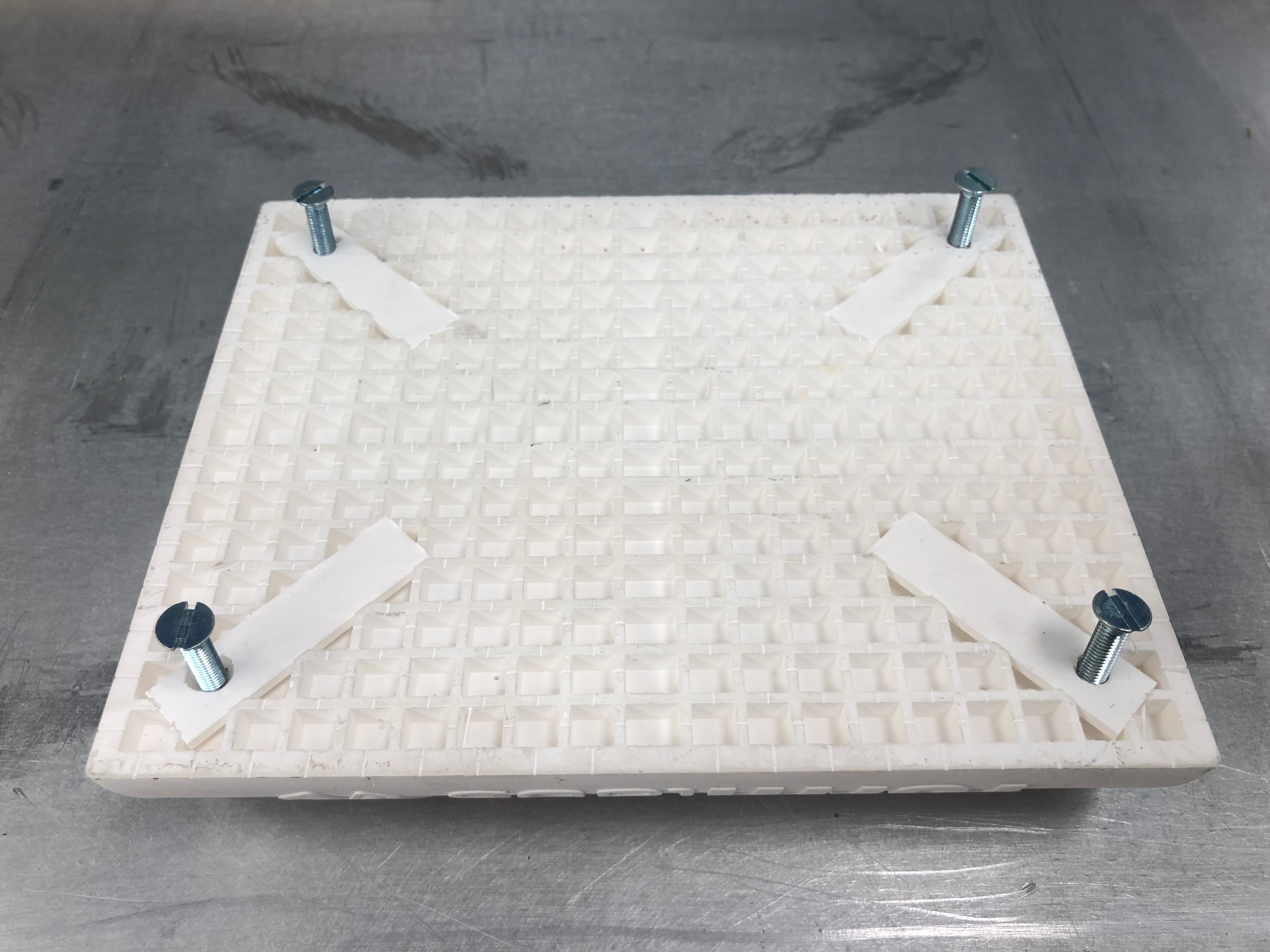
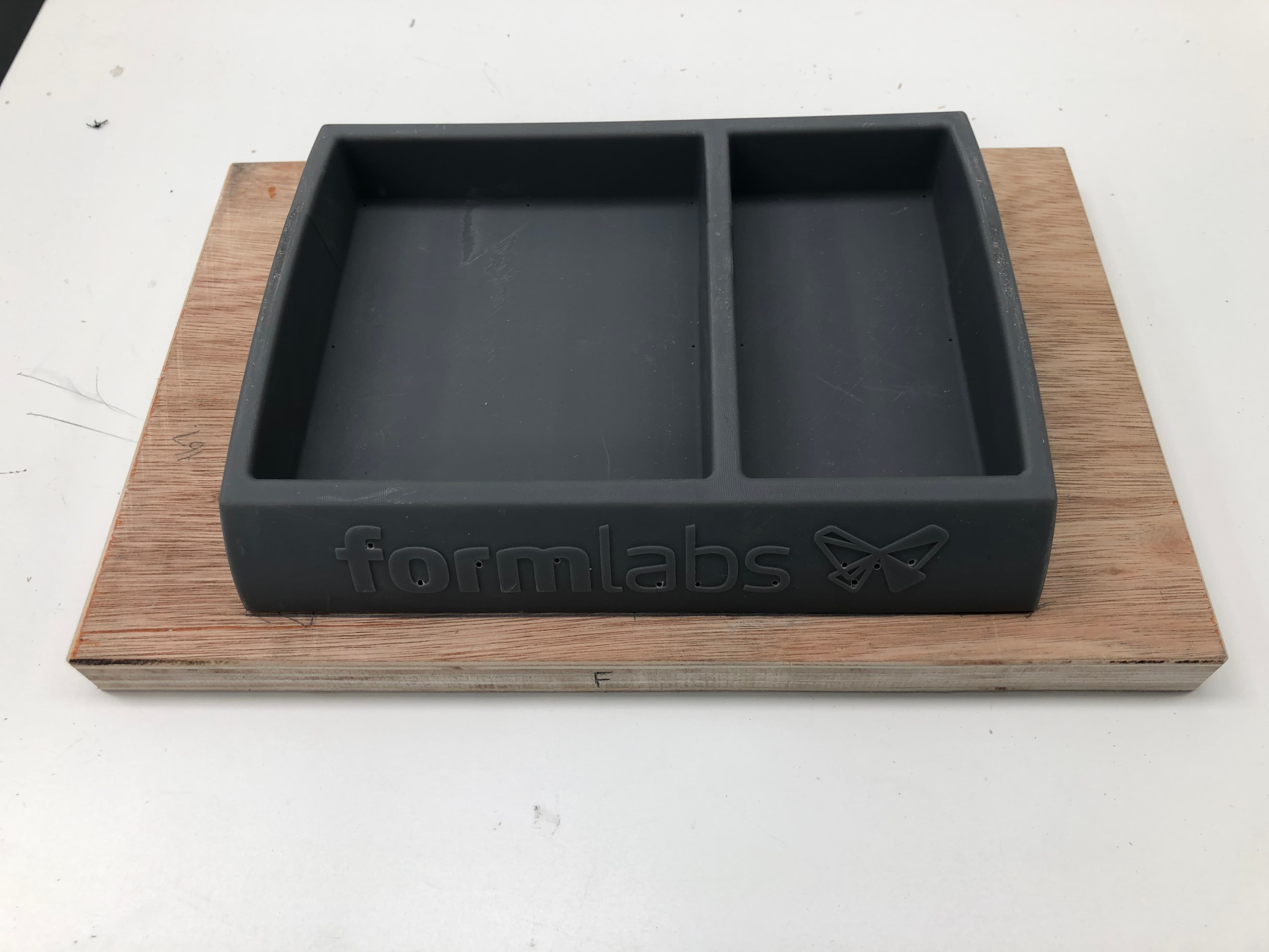
3D printed tools tapped and installed on the baseboard of the thermoformer.
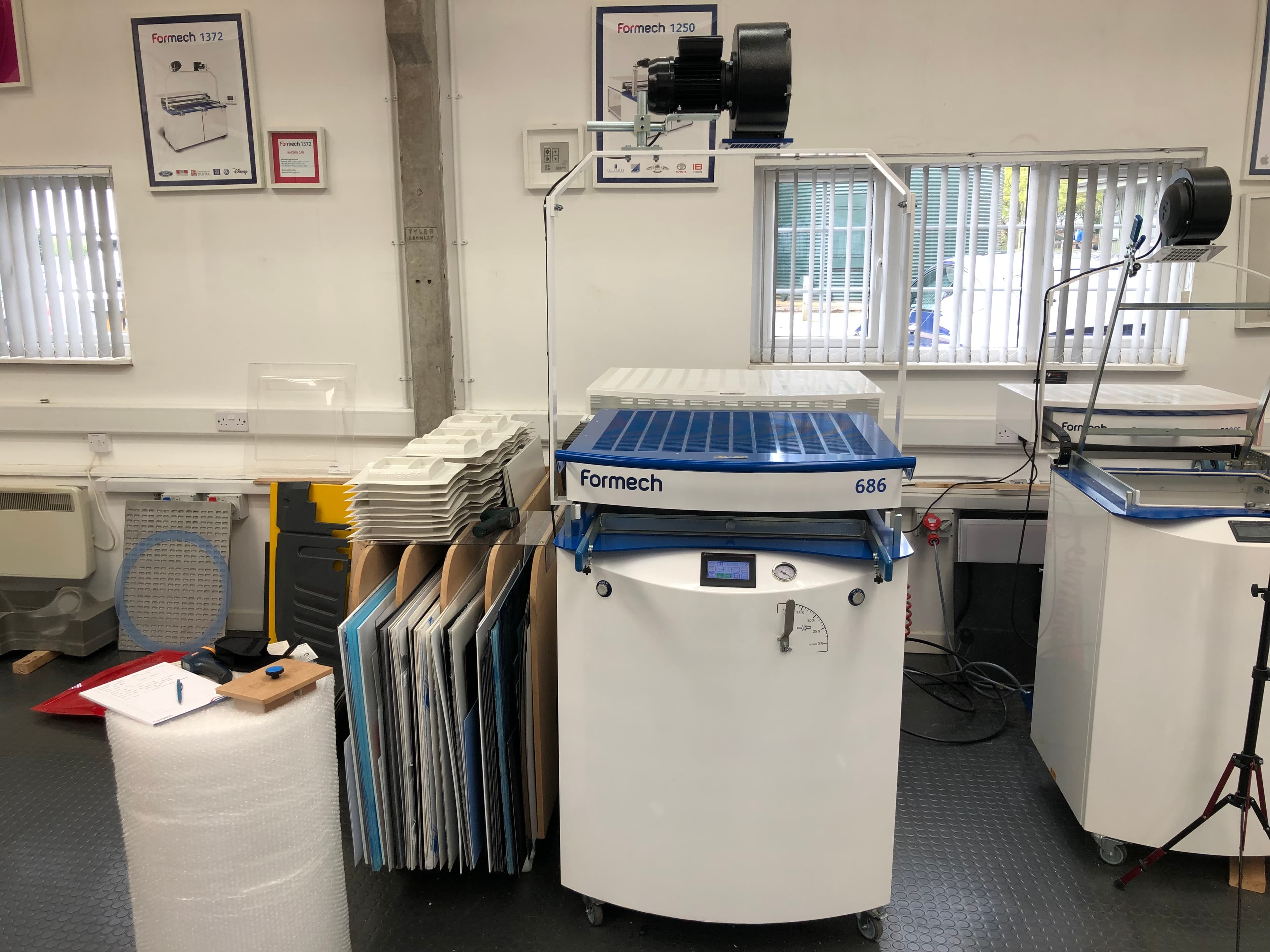
Formech 686 vacuum former.
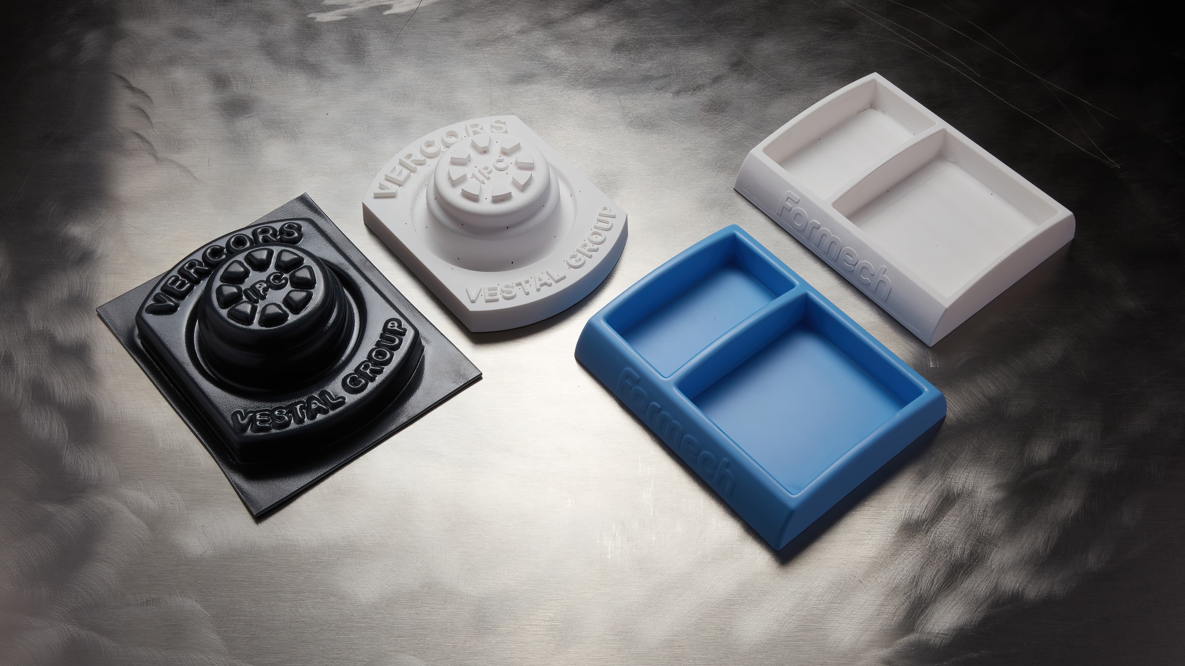
Results
Number of parts formed: 50 parts of 1.5 mm thick ABS and HIPS sheets were formed on each printed tool. The vacuum formings were produced in a similar fashion to conventional production methods with no allowance for the tooling overheating. Consistent cycle times were used.
Quality of the parts formed: The quality of the formed parts was similar to what can be achieved with traditional tooling.
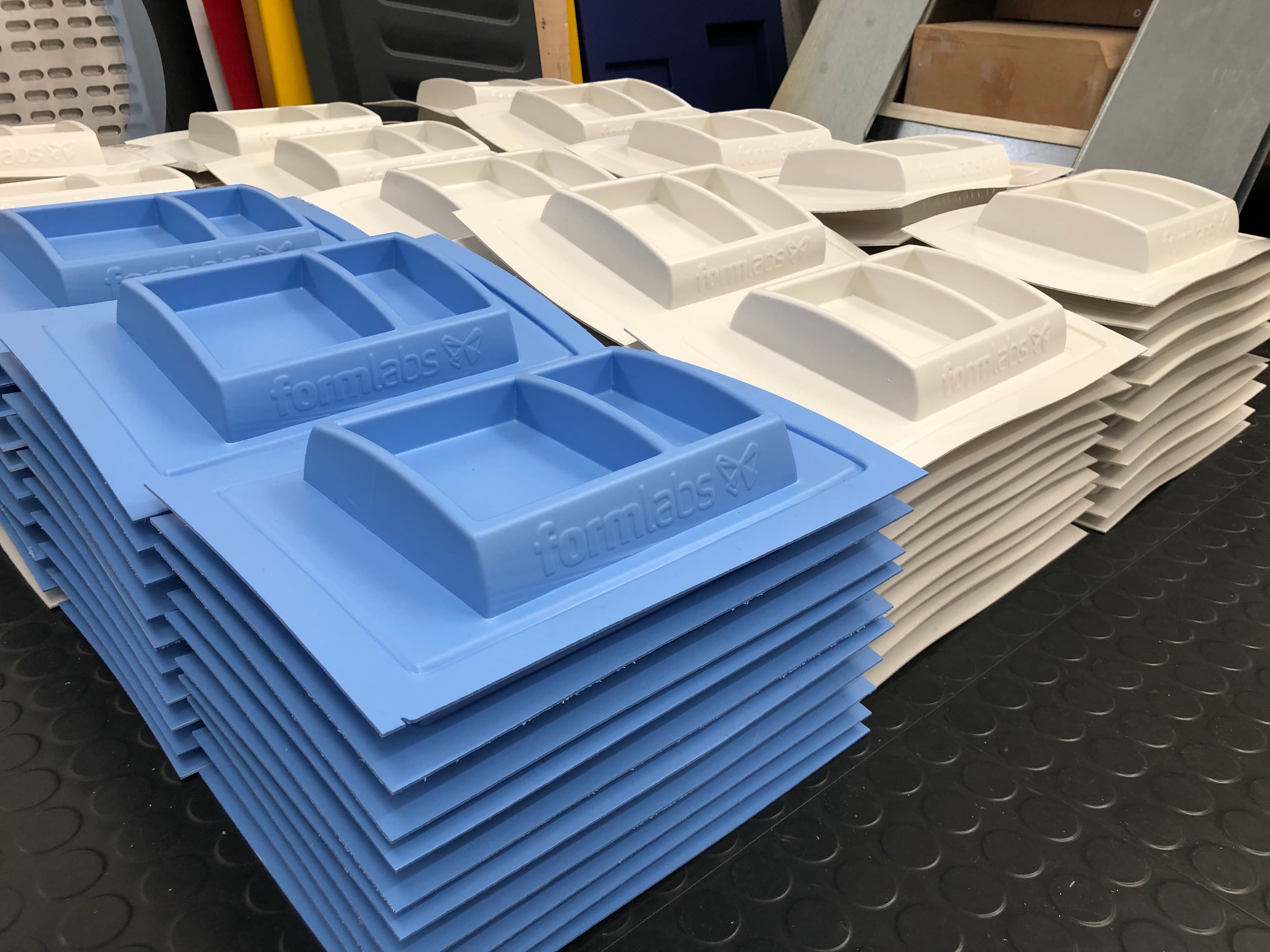
Thermoformed ABS and HIPS sheets.
Mold degradation over time: The Grey Resin mold became slightly flexible at the top of the side walls as the tool heated up, but this did not impact the part quality. The High Temp Resin mold had very little flexibility. The Rigid 10K Resin had no visible movement at all and remained totally rigid throughout the production run.
The team recommends printing in Grey Resin for short production runs and choosing Rigid 10K Resin for larger batches. With crisp details, the Rigid 10K Resin is more robust than the High Temp Resin and would most likely be able to handle a full day of production.
Thermoforming Thin Sheets of PETG, PE, PP for Packaging
For further reference, the Formlabs team completed some testing in-house with various mold geometries for small packaging applications. We thermoformed PETG, PE, and PP sheets with the Ministar S230V from Scheu-Dental. The sheet thickness ranged from 0.5 to 2 mm. The tool dimensions were within 100 x 100 x 20 mm.
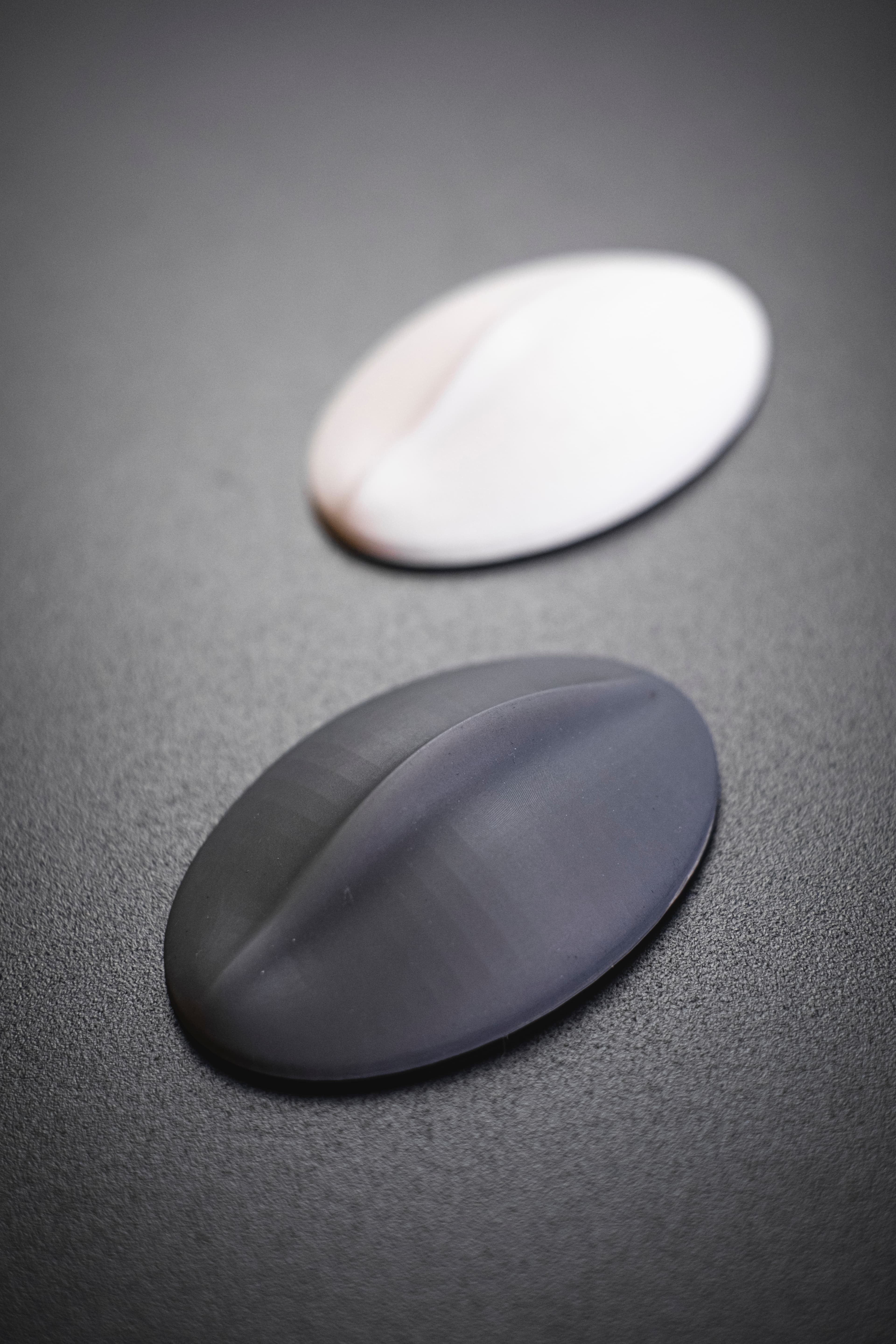
CAD model of the puck, then printed in Grey Resin and Rigid 10K Resin on the Form 4 printer.
| Material | PETG 0.5 mm | PP 1.0 mm | PE 2.0 mm |
|---|---|---|---|
| Pressure (bar) | 1 | 1 | 2 |
| Heating time (s) | 25 | 55 | 60 |
| Cooling time (s) | 20 | 80 | 120 |
| Cycle time (s) | 80 | 210 | 210 |
| Sheet temperature (°C) | 110 | 130 | 110 |
| Mold temperature (°C) after 5 parts | 60 | 60 | 60 |
| Mold temperature (°C) after 10 parts | 60 | 60 | 60 |
| Number of cycles* | 15+ | 15+ | 20+ |
*The number of cycles with a + indicates that the mold was not tested to failure, the mold was still in good condition, and could potentially be used for more cycles.
*The number of cycles with a + indicates that the mold was not tested to failure, the mold was still in good condition and could potentially be used for more cycles.
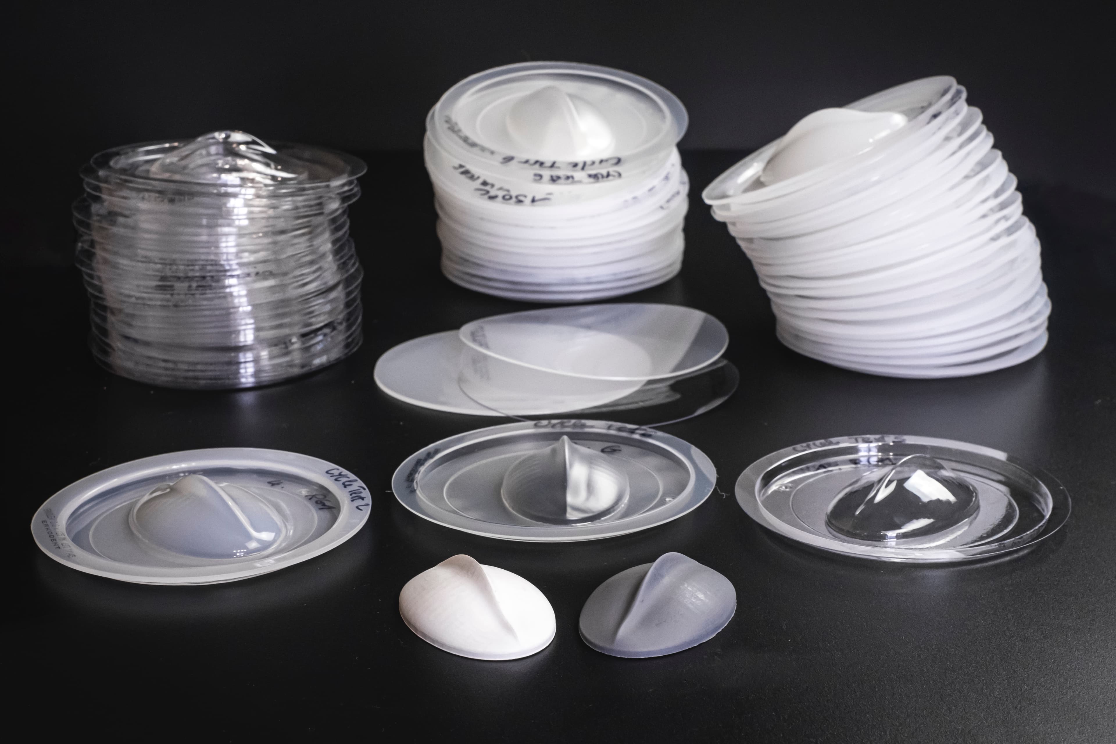
Results
With both tools, we formed 15 to 20 parts with each material, and stopped the trials without mold deterioration. Here are some observations:
- The temperature of the tools stabilized at around 60 °C after a few iterations.
- For very thin sheets (0.5 mm) at a short cycle time (80s), the quality of the vacuum forming decreases after about 10 iterations and the part is harder to demold.
- For sheets around 1-2 mm thickness at longer cycle times, the demolding is easier and the part quality higher.
These tests suggest that the tools could produce dozens of parts without failure. For small size parts and thin sheets, Grey Resin should be strong enough to handle the process. However, depending on the geometry, we could observe warping over time due to long exposure to heat.
We recommend printing with the Grey Resin for producing low quantities of small parts, and choosing the Rigid 10K Resin for larger parts and higher volumes of production.
Conclusion
Desktop 3D printing is a powerful solution to fabricate thermoforming molds rapidly and at a low cost, for custom parts or short-run production. This report documented how SLA 3D printed tools were employed to thermoform dozens of parts from common thermoplastics in a matter of days.
The industry is only starting to explore the potential of 3D printed thermoforming tools, and could even expand to high-performance applications such as fiber reinforced composites molding. 3D printed rapid tooling is also ideal for cost-effectively manufacturing custom end-use parts in the healthcare sector. In particular, pressure forming over 3D printed models is the go-to method for producing clear aligners in orthodontics.
Today, 3D printing is being used to drive efficiency at each stage of the product development process, from directly 3D printed early rapid prototypes, to pre-production parts and limited series with rapid tooling on the factory floor. Beyond prototyping, 3D printing enables on-demand custom tooling, adding flexibility to manufacturing processes by rethinking the way tools are made. It enables manufacturers to meet changing business needs quickly and makes affordable, low-volume production feasible in-house.
Do you have questions about using an SLA printer for thermoforming? Reach out to our specialists or request a free sample of one of our materials.