
When we announced the Form 3 and Form 3L in April, we explained why we re-engineered stereolithography 3D printing into our own Low Force Stereolithography (LFS)™ technology. LFS 3D printing uses a flexible resin tank to significantly reduce peel forces during printing and a Light Processing Unit (LPU), our custom-designed enclosed optics engine, to produce consistent, accurate prints.
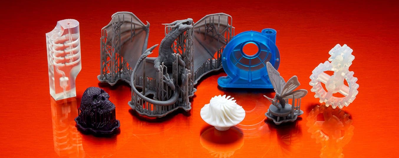
In this post, we'll explore how LFS 3D printing directly impacts print quality and throughput through key improvements across four categories: surface detail, surface finish, support structures, and part accuracy.
Curious to see the quality firsthand? Request a sample part printed on the Form 3.
Print Highly Detailed Models Like Never Before
Inside the Form 3 and Form 3L is a custom enclosed optics engine, the Light Processing Unit (LPU). The LPU achieves a crisp, clean laser spot through several enhancements. The laser beam passes through a spatial filter to catch any stray light and a series of mirrors ensure that the beam is always delivered perpendicular to the print plane.
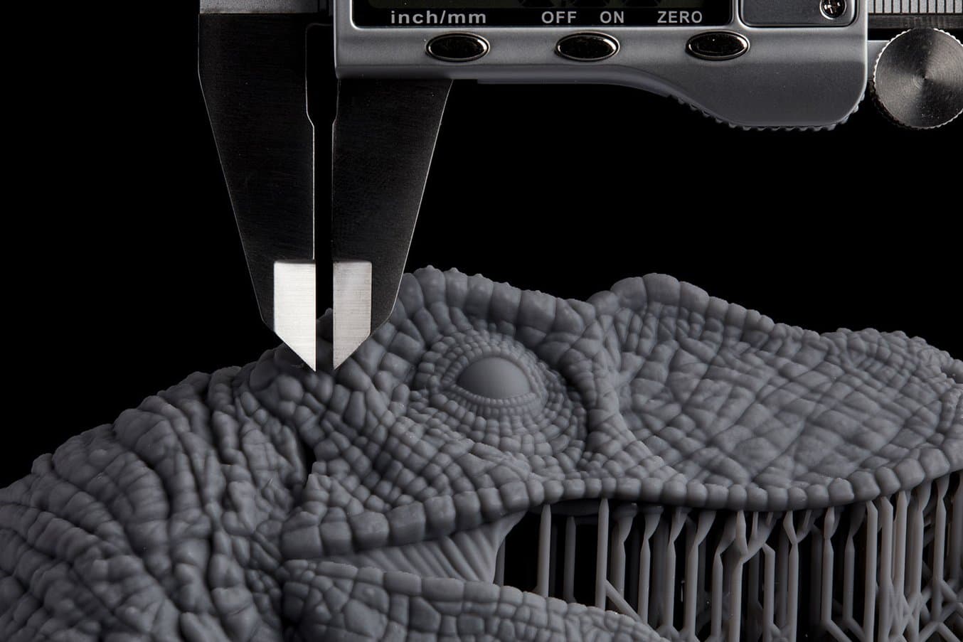
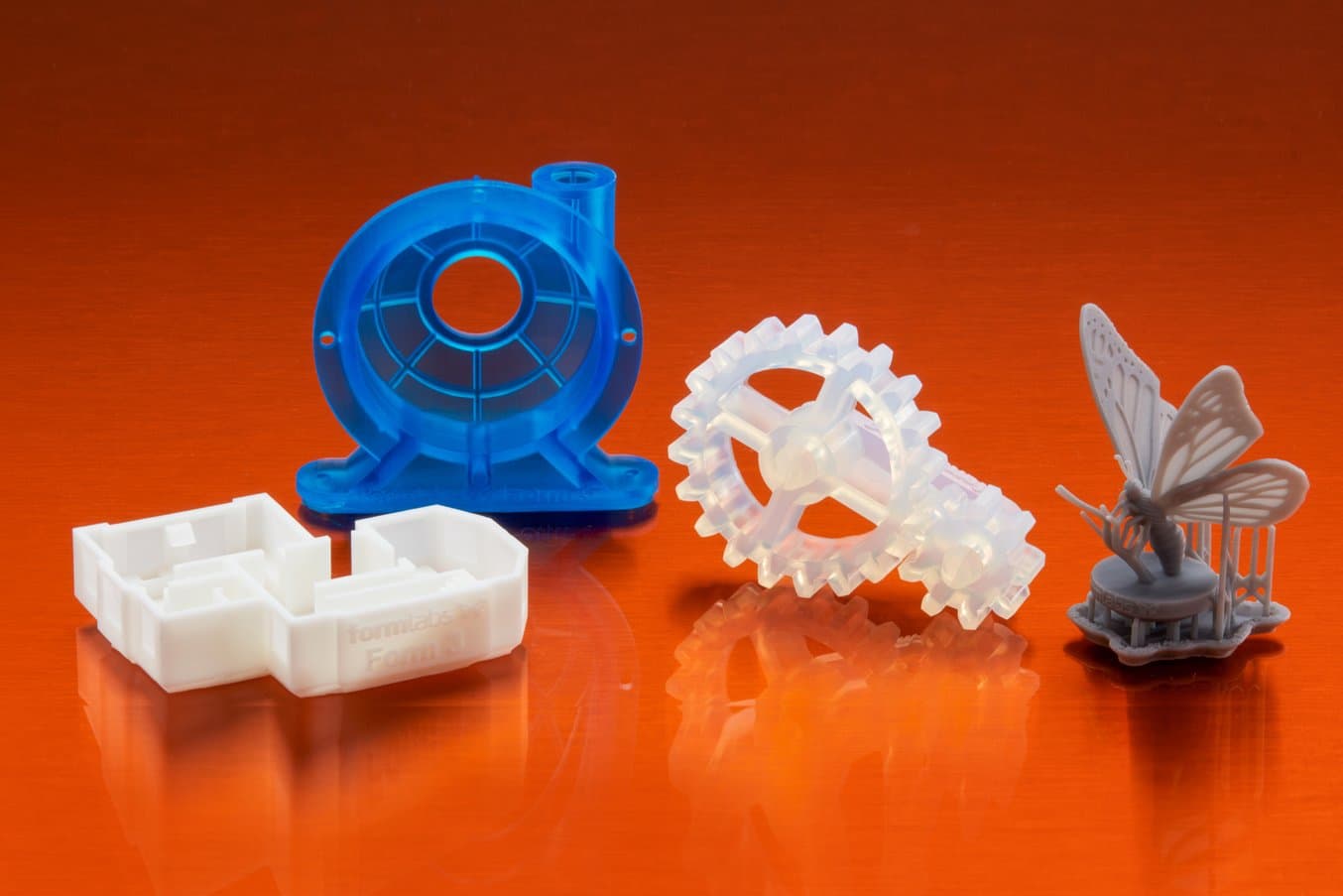
The linear path of the laser ensures that fine details such as holes, embossed text, and small features print with sharp edges. Low Force Stereolithography prints parts with impressive surface detail and fine features once impossible to achieve on the desktop.
“One of the most exciting things about the Form 3 is where the low force print process brings us in terms of print quality and finishing. We’re excited about how we can push the limits of particularly really tiny features. I am amazed at the small details that show up in models. It's really impressive.”
—Sean Buxton, Senior Mechanical Engineer, Ximedica
Smooth Surface Finish, Even at 100 Microns
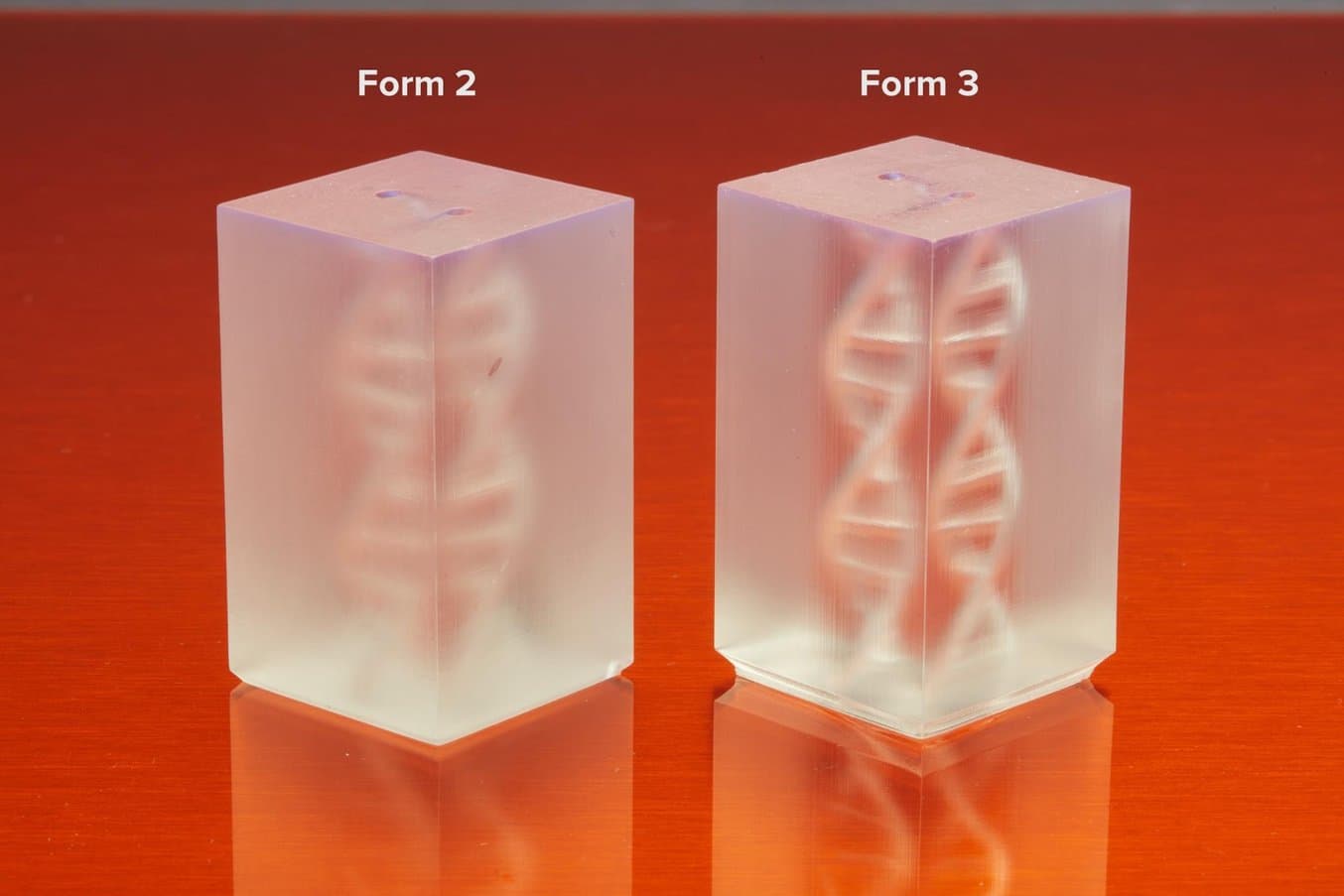
The surface finish of a 3D printed part is ultimately a result of good layer registration, or how accurately each layer is aligned with the previous layer. When layer registration is good, layer lines become closer to invisible. As a result, surface roughness is reduced, which ultimately leads to a smooth finish, and for clear materials, more translucent parts.
As each layer of resin is cured, a bond forms between the printed part and the tank. The peel process breaks this bond, allowing the part to move up and the next layer to print. In most inverted stereolithography 3D printers, this separation exerts a great deal of force on the part, which can lead to rough surfaces (which the Form 2 accounts for with a great deal of calibration).
In Low Force Stereolithography 3D printing, the flexible film at the base of the resin tank gently peels away as the build platform pulls the part up. This significantly reduces stress on the part (internal testing shows up to a ten times reduction in peel forces compared to the Form 2), allowing for a step change in surface finish and part clarity.
“Our first impression of the Form 3 was the quality of the print. The first print that we did came out amazing. The texture didn't really show the layers. Hypertherm historically makes jewelry. When I say jewelry, I mean really fine finish, shiny nice soft edges, the details. In terms of our inspection processes, we're very, very particular about having as close as possible to perfect.
A 3D printing solution that offers a nice quality finish and requires less post processing is important to us. It's a lot less handwork on our end: the less we have to handle an Exacto blade or sandpaper, the better. Being able to print with that level of surface finish is important for functional assemblies.”
—Aaron Noyes and Dan Harrington, Senior Prototype Machinists, Hypertherm
Light-Touch Supports for Better Throughput
In a recent part finishing survey of Form 2 users, 47% said removing supports was their biggest pain point and 62% mentioned supports as the best place to improve their part finishing process.
For almost any 3D printing technology, post-processing—including removing support structures, sanding, and finishing parts—adds time and limits throughput. Support marks left behind have a negative impact on surface finish.
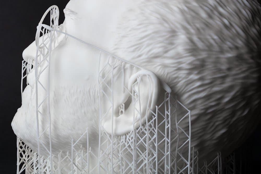
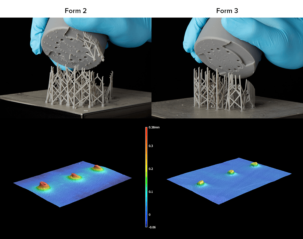
New light-touch supports set out to address this common frustration. These new support structures use very small touchpoints to enable easy removal with minimal support marks left behind. They are also trussed together more strongly, so when the part is removed from the supports, the supports tend to stay behind as a single lattice.
This leads to about four times less support material left behind, which means less time spent post-processing and less need for additional sanding. For the diagram below, parts were printed with touchpoint density of 0.8 and touchpoint size of 0.6 mm for the Form 2 and touchpoint density of 0.5 and touchpoint size of 0.3 mm for the Form 3 and shot at 38 times magnification.
"The improvements to the light-touch supports that break away are game-changing. There is no way to describe the first time you take a part and pull at it and it just seamlessly pops completely free. It takes the stress out of building and cleaning parts and lets us keep our focus on design and creation."
—Justen England, Managing Director, Delve
Accurate, Repeatable Printing
The Form 3’s optics are fully enclosed within a custom-designed Light Processing Unit (LPU). Within this enclosed optics module, the laser beam is passed through a spatial filter that catches any stray light to ensure a clean laser spot. The laser is then directed down to a single galvanometer to position it in the Y direction, then to a fold mirror, then to a parabolic mirror to straighten it out before it exits the LPU window directly below the print surface.
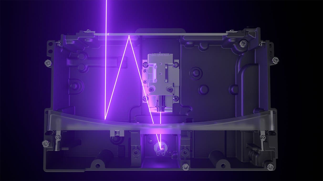
A stepper motor drives the entire LPU in the X direction in a smooth line-scanning motion. Combined with the perpendicular light path of the laser, this creates what we refer to as linear illumination. This line-scanning process delivers 25 micron XY resolution consistently and reliably over time.
This XY resolution of 25 microns describes how precisely the printer can draw in the XY plane: the laser moves in 25 micron "steps" in the X direction. The 85 micron laser spot size is essentially the size of the brush tip. Because of constant line scanning process, the Form 3 can consistently deliver parts with 25 micron XY resolution. (This number was harder to define with the Form 2 because of differences in the process.)
Keep an eye out for an in-depth accuracy study of parts printed on the Form 3 soon.
Request a Sample Part
Curious to see the quality firsthand? Pick an application and we'll ship a sample part printed on the Form 3 to your office.
Request a Free Sample PartThe Next Generation of Industrial 3D Printing
Formlabs has set out to provide the tools for any business to access high-quality fabrication. The Form 3, built on advanced Low Force Stereolithography (LFS) technology, is the next step toward universalizing industrial-grade 3D printing for the desktop and bringing professional fabrication in-house.
Order Your Form 3 Today Compare Formlabs SLA Models