
This post was written by Formlabs engineer Timur Senguen.
Reliability is the hallmark of mature technology. As such, it’s increasingly becoming the focus of online discussions and marketing pushes as 3D printers become more accessible. In an attempt to demystify a nebulous term, we’re excited to show you how we evaluate reliability and tune every aspect of our desktop 3D printers to be as reliable as possible.
Previously, we explored why 3D printer resolution is difficult, though not impossible, to evaluate from reported numbers. Reliability is more important, and perhaps even harder to pin down. Since the start of development of the Form 2, we have been collecting mountains of data internally on print quality and reliability.
In this blog post, we’ll walk through how we measure reliability and what it means for your Form 2 prints. In an upcoming series of blog posts, we’ll break down what we found and how the Form 2 performs in each of these categories based on the data.
What Exactly Is “Reliability”?
In the context of additive manufacturing, reliability has multiple meanings. Each speaks to a different situation, but all pertain to one underlying question: “If I print something, will it meet my expectations?”
We can break down this question further into 4 categories: If I print something, will it…
- Print the same as last time? Print-to-print reliability.
- Print the same on all of my printers? Printer-to-printer reliability.
- Print the same the first time and the 100th time I print it? Ongoing reliability.
- Complete successfully? Field reliability.
Print Quality Testing
The first step in our Reliability Testing process is defining what properties of printing are important and how to collect them at a resolution that’s actually interesting. For example, we could have simply printed a cube and used a binary scoring system (Prints = 1, Doesn’t Print = 0), but that’s not really the level of print quality Formlabs printers are known for.
We needed something a bit more complex. Enter the “Formtest.”
The Theory Behind The Formtest
The Formtest is a model that can be used to evaluate the performance and reliability of a 3D printer. The part’s features help us assign quantitative scores related to printer performance.
In designing the Formtest, we identified four aspects as most likely to vary between printers and multiple prints within printer:
- Positive features (wires, walls, etc).
- Negative features (holes, slots, etc.).
- Structural features (bridges, overhangs, etc.).
- Dimensional accuracy (small dimensions, larger dimensions).
Realistically, these four aspects are not completely orthogonal (for example, negative features are really multiple positive features encasing a negative space). There are theoretical scenarios where the quality of each can vary independently from the others. This means we need to test for each aspect individually, rather than make inferences via results from the others.
The Formtest in the Lab
At Formlabs HQ, the Formtest is probably the most frequently printed part, other than the Rook (which you can request as a free sample).

Any time we make changes or introduce new software, process, material, or resin, we use the Formtest to evaluate the most important performance aspects. Even if the change or new development passes validation testing on the first attempt, the team still prints between 16 and 32 Formtests to make sure that all is well across several printers and that print success is repeatable.
We don’t stop at the Formtest when performing our validation testing, but it’s always included no matter what. Because this standardized test part has data ranging back as far as the first printer we released, the Form 1, we can make scientifically-backed, data-driven decisions.
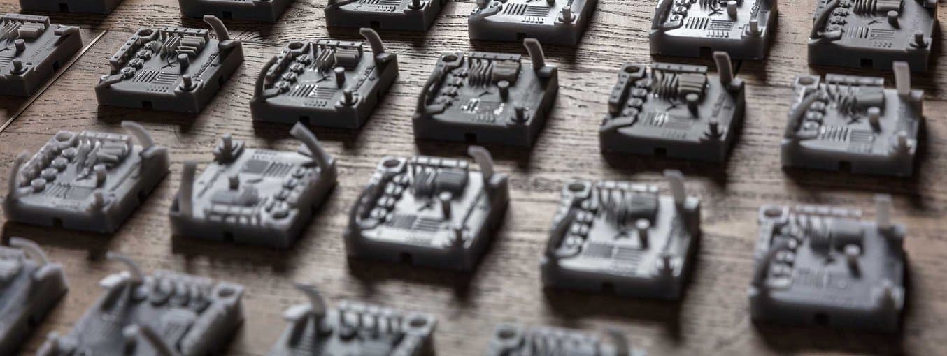
Anatomy of the Formtest
After several attempts at theorycrafting the perfect test part and multiple rounds of practical iteration, the Formtest v1 emerged as a good compromise between intended goals, degree of difficulty, and practical considerations like print time and resin usage. After all, reliability testing means having to print multiple hundreds of this particular part.
The Formtest v1 contains features for all four categories mentioned before as well as a fifth “functional” category to relate the results to real world applications:
- Positive features: wires and two sets of walls.
- Negative features: holes and two sets of slots.
- Structural features: two sets each of bridges and overhangs.
- Dimensional features: base and octagonal-base cylinder with known dimensions.
- Functional features: M4 nut hole, M4 bolt, M4 threaded hole.
The range of sizes of the positive and negative features were chosen such that the smallest of each should be just achievable on the average Form 2 printer. Any loss of quality is immediately indicated by the absence of the smallest feature, like the thinnest wire or the smallest hole. More severe diminishing of print quality will result of the absence of the next smallest feature and so on, allowing us to grade each set of features on a scale of 0-5. The Formtest is designed such that certain qualities, on average, are just within the capabilities of the Form 2. We’ll talk more about this in a future post.

Structural features, like bridges with spans of varying lengths and overhangs of obtuse to acute angles, serve as indicators for loss of green strength, changes in peel forces, and issues with layers on the underside of parts. Again, the score here is discretized, but on separate scales.
To determine dimensional accuracy, both orientations of the base and the four orientations of the cylinder can be measured with a micrometer or, if you don’t have one, a set of calipers. When measuring these dimensions, proper post-curing techniques are particularly important; an undercured part is typically oversized by up to 200 microns compared to the fully cured version. Deviations from the intended sizes (50 mm for the base, 4 mm for the cylinder) were tabulated and fit to a statistical scoring model after all data was collected.
To put it all together, the following functional features were included:
- Nut cut-out.
- Threaded bolt.
- Hole.
These are intended to tie any scores and findings of the previous categories to real life effects: if the part isn’t produced perfectly, would it be noticeable? Using store-bought M4 nuts and bolts, each feature is tested and evaluated binarily to yield a score between 0-3.
In addition to the presence of each of these features, the part is functionally symmetrical along the diagonal, making orientation on the build platform a non-issue. The text serves as a way to distinguish parts from each other as all printed parts will, ideally, look the same.
Generate Your Own Formtest
You can generate your own Formtest by following these instructions:
- Download the code (click on the download button between raw and clone)
- Visit OpenJSCAD.org.
- Drop the file previously downloaded at the bottom left to load the code and render the 3D file.
- Edit Printer Name (optional).
- Edit Print Identificaiton to differentiate models between themselves (optional).
- Click “Generate STL”.
- Click “Download STL”.
- Open your own Formtest file in PreForm and print it!