
리버스 엔지니어링은 물리적으로 존재하는 부품에서 디지털 설계를 만들어 내기에 좋은 방법으로 3D 스캐닝과 3D 프린팅 같은 기술과 함께 사용하면 프로토타이핑 툴킷 중에서도 값진 도구가 될 수 있습니다.
3D 스캐너는 복잡한 물체를 아주 빠르게 측정하여 실제로 참조하면 디자인 워크플로 속도를 엄청나게 가속할 수 있습니다. 물리적 형태를 캡처하고 수정하는 기능을 이용하면 각양각색의 기존 제품에 완벽하게 들어맞는 3D 프린팅 파트를 설계할 수 있습니다. 3D 프린팅 지그로는 드릴이나 톱의 위치를 반복해서 잡거나 접착제와 함께 파트를 정밀하게 조립할 수 있습니다. 샌드블라스팅, 페인팅 또는 에칭용으로 적절하고 재사용 가능한 마스크를 만듭니다.
이 가이드에서는 애프터마켓 디지털 게이지의 단계별 리버스 엔지니어링 프로세스를 살펴보고 3D 프린팅을 위해 파트를 스캔하는 방법과 올바른 리버스 엔지니어링 도구를 사용하기 위한 팁( CAD 소프트웨어 ~ 레진 3D 프린터)을 설명합니다.
전문 3D 프린터용 3D 스캐너를 찾고 계십니까? 3D 프린터와 함께 사용할 최고의 3D 스캐너 선택을 다룬 자세한 가이드를 읽어보세요.
무료 상담 예약하기
저희 3D 프린팅 전문가와의 1:1 상담하시면 귀사의 비즈니스에 적합한 솔루션을 결정하고 ROI 분석, 테스트 프린트 외 다양한 것을 받아보실 수 있습니다.
현실에서 디지털로: 메쉬와 솔리드
물리적 개체를 디지털로 변환할 때 사람들이 직면하는 가장 큰 문제 중 하나는 메쉬와 솔리드 두 가지 유형의 3D 모델 간의 호환성이 크게 좋지 않은 점입니다.
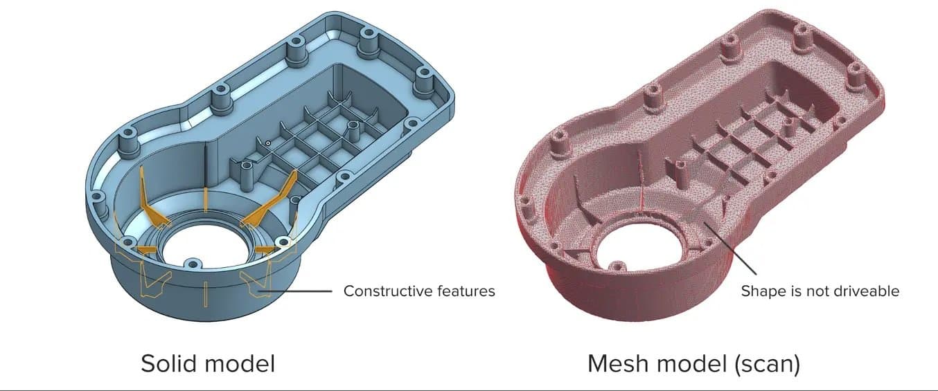
3D 스캐너로는 편집할 수 있는 "솔리드" 모델이 아닌 메쉬를 얻을 수 있습니다. 메쉬를 편집할 수 있게 하려면 리버스 엔지니어링을 거쳐야 합니다.
메쉬는 모든 3D 스캐너의 주요 산출물이며 3D 프린터(STL)에서 일반적으로 이해되는 형식입니다. 메쉬는 모서리와 모서리가 연결된 많은 수의 삼각형이 있는 모양의 표면을 나타냅니다. 메쉬 모델에는 모양을 정의하는 삼각형의 위치 외에 객체에 대한 정보가 포함되어 있지 않습니다.
반면에 엔지니어는 솔리드 모델로 작업하도록 교육을 받습니다. 솔리드 모델은 객체가 어떻게 설계되었는지에 대한 정보를 담고 있으며, 이 정보는 논리적 단계의 '스택'에 있는 기능으로 모델에 명시적으로 인코딩됩니다. 솔리드 CAD에서는 단일 피처의 치수를 변경할 수 있으며 모델의 나머지 부분은 업데이트되어 변경 사항이 적용됩니다.
메쉬에는 개체 구성에 대한 정보가 부족하기 때문에 메시 모델을 변경할 수 있는 방법이 제한적입니다. 솔리드웍스(Solidworks), 온쉐이프(Onshape) 같은 CAD 소프트웨어로는 메시를 직접 수정할 수 없습니다. 스캔한 부품의 기본 설계를 크게 변경해야 하는 경우 메쉬를 솔리드 CAD 도면으로 변환해야 하며 이 프로세스가 리버스 엔지니어링입니다.
최신 제품 개발 프로세스 중 3D 스캐닝의 역할
Peel 3D와 함께하는 웨비나에서 3D 스캐너의 3D 프린팅 워크플로 통합으로 제품 개발 프로세스를 개선하는 방법을 알아보세요.
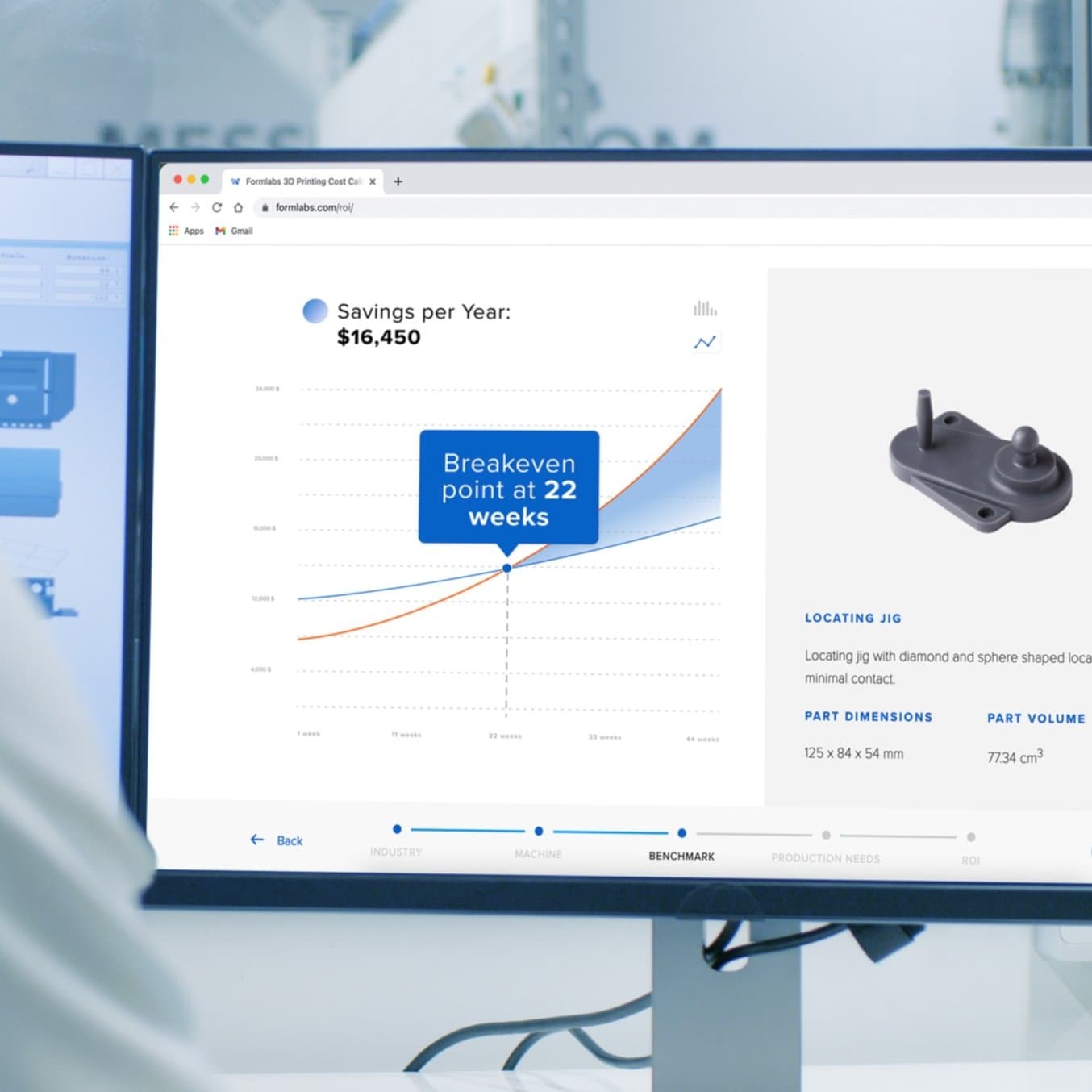
시간과 비용 절감 효과 계산
Formlabs 3D 프린터와 인터랙티브 ROI 도구로 얼마나 많은 시간과 비용을 절감할 수 있을지 확인해 보세요.
3D 프린팅용 물체 스캔 방법: 리버스 엔지니어링 워크플로
초기 CAD 설계에 액세스할 수 없는데 이전 설계를 참고하거나 통합하여 새 파트를 생성하려는 경우 리버스 엔지니어링이 중요한 역할을 합니다.
예를 들어 기존 제품이 손상되었는데 원래 디자인과 맞아 떨어지는 교체용 부품을 만들거나 리버스 엔지니어링 프로세스를 이용해 기존 개체의 복잡한 표면을 3D 프린팅이 가능한 지그 안에 통합할 수 있습니다. 이 방법은 대량 제조 및 수공예 제품을 수정할 때 유용합니다.
리버스 엔지니어링은 종종 새로운 디자인을 기존 컴포넌트로 조립하기 위한 기초로 사용됩니다. 모든 관계형 객체를 모델링하지 않으면 CAD에서 어셈블리에서 발생할 수 있는 모든 잠재적 문제를 파악하기 어려울 수 있습니다. CAD에서 먼저 파트를 리버스 엔지니어링하려고 하면 많은 비용이 드는 시행착오를 겪을 수 있습니다. 3D 프린트를 사용하면 리버스 엔지니어링된 설계를 실제 공간에서 빠르게 테스트하고 반복할 수 있어 문제를 훨씬 쉽게 파악할 수 있습니다.
대규모 디자인 변경 외에도 측정 오류로 인해 발생할 수 있는 끼워맞춤 문제를 인식하는 것이 중요합니다. 대상 물체에 언더컷, 매우 얇은 보스(표면 위로 솟아오른 부분) 또는 스캔하기 어려운 깊은 포켓이 있는 경우, CAD에서 누락된 영역을 채우기 위해 추측을 사용해야 할 수 있습니다. 프린트된 프로토타입을 물리적으로 조립하면 새로운 수정 사항이나 스캔으로 인한 측정 오류 등 디자인에서 발생할 수 있는 공간적 충돌을 빠르게 찾아 해결할 수 있습니다.
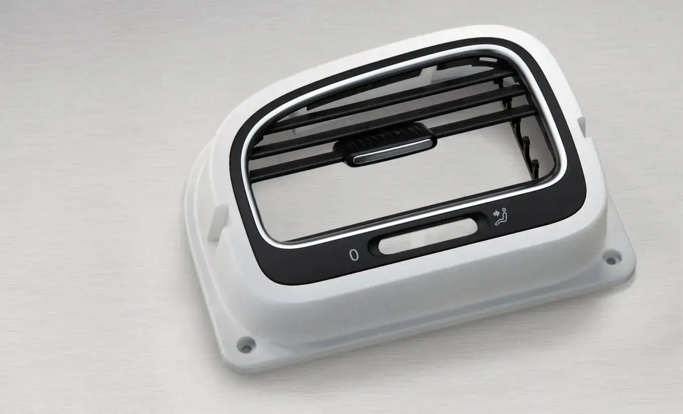
리버스 엔지니어링 워크플로의 기본 단계를 설명하기 위해 폭스바겐 골프(Volkswagen Golf)의 통풍구에 맞는 애프터마켓 디지털 게이지용 어셈블리 지그를 만드는 프로세스를 살펴보겠습니다.
1. 물체 스캔 준비
대상물에 임시 무광 파우더를 스프레이 하여 스캔 정확도를 증진합니다. 표면에 광택이 조금이라도 있다면 스캔 품질이 낮아지는 경향이 있으므로 반사가 생기거나 투명한 표면은 무광 코팅 없이는 절대로
스캔할 수 없습니다.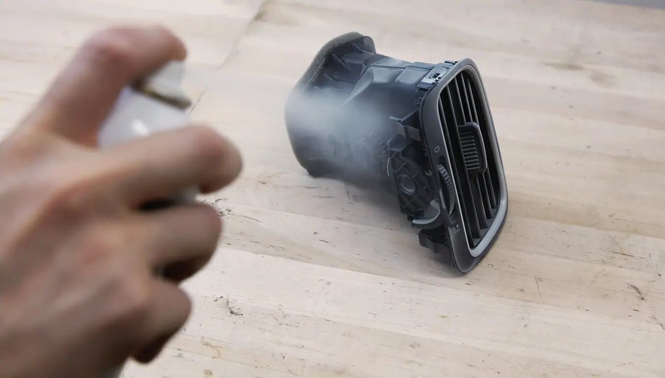
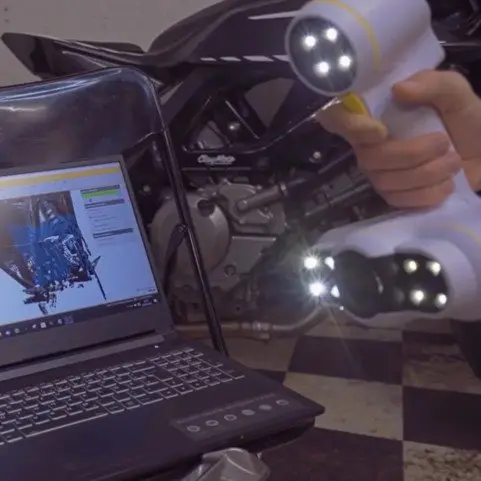
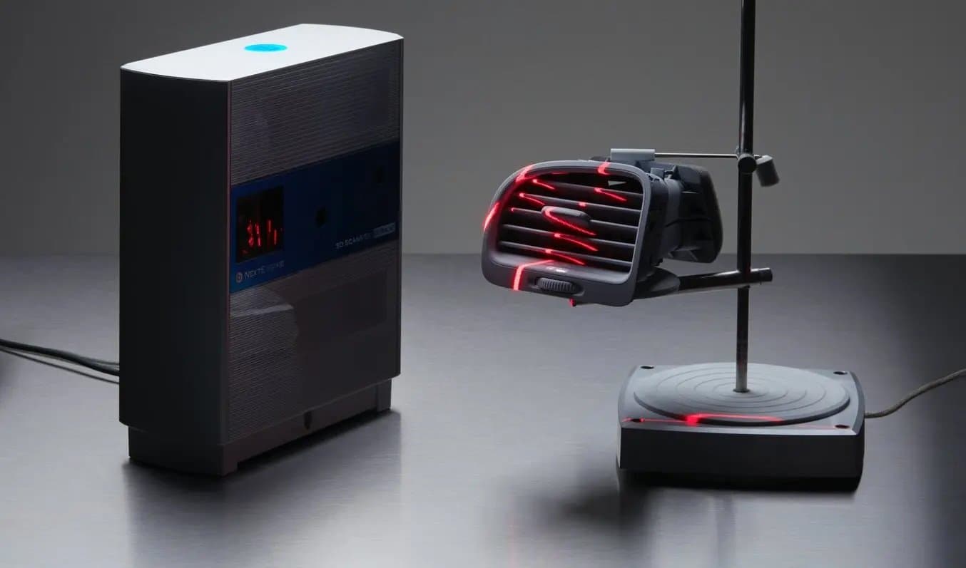
2. 물체 3D 스캔
고정밀 3D 스캐너로 파트의 중요한 부분을 캡처합니다. 탁상용 구조광 스캐너 또는 레이저 스캐너는 정확도가 ±100 이상인 작업에 적합한 도구입니다.
주의: 물체에 깊은 홈이 있는 경우 물체의 방향을 정하고 여러 번 다시 스캔해야 할 수 있습니다.
3. 메쉬 다듬기
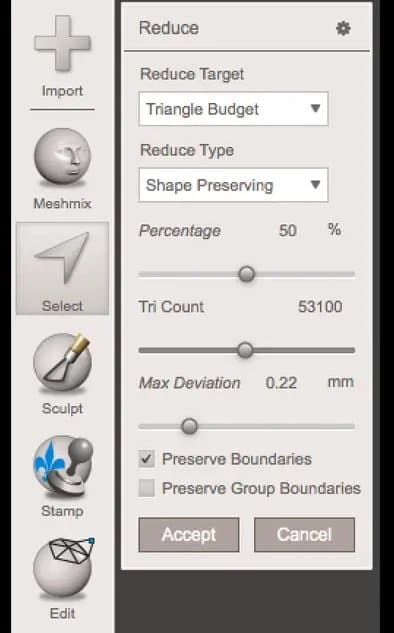
일부 스캐너에서 생성되는 메쉬 파일은 지나치게 커서 이후 단계가 서서히 멈춥니다. 스캐너 소프트웨어를 이용하면 작은 틈을 메우고 스캔 데이터를 단순화하여 CAD에서 데이터를 보다 쉽게 관리할 수 있습니다. 가능한 한 중요한 디테일을 훼손하지 않는 선에서 모델을 최대한 축소합니다.
팁: 더 많은 부분을 제어해야 할 경우, Meshmixer는 스캔한 메쉬를 다듬기 위해 고를 수 있는 훌륭한 선택지가 됩니다.
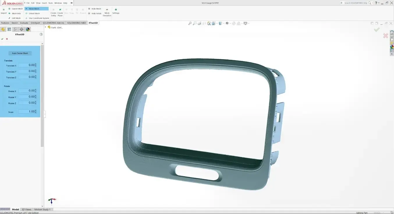
4. 메쉬를 CAD로 불러오기
리버스 엔지니어링 도구가 장착된 CAD 소프트웨어에 메쉬를 가져옵니다. 솔리드웍스용 Geomagic은 복잡하고 유기적인 형태의 표면을 다듬기에 강력한 도구입니다. 비교적 단순하고 평평한 표면이 있는 부품을 리버스 엔지니어링하는 데는 Xtract3D가 저렴하고 가벼운 대안이 될 수 있습니다.
이 단계에서는 스캔 메쉬를 기존 디자인 구성 요소와 정렬되도록 옮기고 회전합니다.팁: 직교 보기 방향을 향하도록 스캔을 회전하고 정렬하면 도면을 더 쉽게 도출할 수 있습니다.
5. 중요한 표면 추출
CAD 도구로 편집할 수 있는 솔리드 모델을 생성하기 위해 스캔 형태를 추출하는 경로에는 반자동 표면 처리, 자동 표면 처리, 수동 다시 그리기의 세 가지 경로가 있습니다.
반자동 표면 처리
복잡한 굴곡이 있는 표면은 수동으로 그리기 어려우므로 반자동 표면 처리를 선택하여 사용할 수 있습니다. 이 기능은 감지된 스캔 영역에 맞게 표면을 생성합니다. 표면 감지 기능의 감도를 변경해가며 다양한 표면을 찾을 수 있습니다.
팁: 솔리드웍스용 Geomagic은 스캔에서 표면을 감지하여 3D 곡선에 맞춥니다. "브러시"를 사용하여 각 영역에서 스캔 영역을 수동으로 추가하거나 뺍니다.
모든 표면을 감지하려면 민감도 설정을 다양하게 변경해가며 이 과정을 여러 번 반복해야 할 수도 있습니다. 그런 다음 이러한 표면을 트리밍하고 결합하여 편집 가능한 솔리드를 만들 수 있습니다.
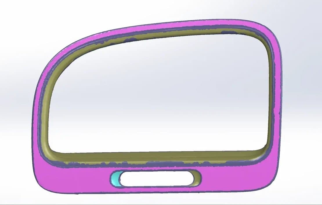
향후 편집 가능성을 최대한으로 확보하고 싶거나 날카로운 모서리의 정확도가 중요한 경우 반자동 서피싱을 사용하여 곡선 모양을 다시 만듭니다.
트리밍 후 리서피스한 결과입니다.
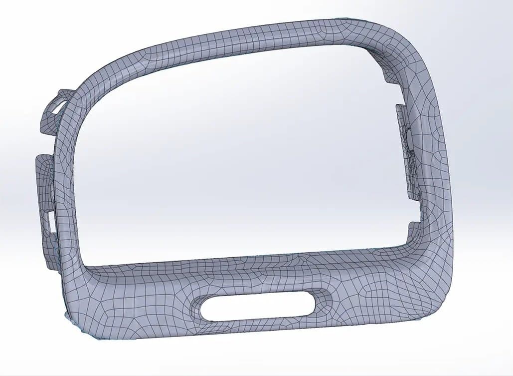
자동 서피싱
자동 서피싱을 이용하면 어떤 조밀한 스캔 모델로부터도 솔리드 모델을 생성할 수 있습니다. 표준 CAD 도구로 이 자동 표면 처리된 형체를 빼거나 추가할 수 있지만 형체 자체에서 기본 피처를 옮기는 것은 더 어려울 것입니다.
가장자리 배치를 제어할 필요가 없을 수도 있습니다. 예를 들어, 인체 공학적인 형태의 맞춤형 제품을 만들기 위해 인체의 일부를 스캔하거나 수제 개체를 정확하게나 반복해서 수정하는 데 필요한 지그를 만들려는 경우입니다. 이러한 경우 자동 서피싱은 모델링 시간을 절약할 수 있는 좋은 방법입니다.
주의: 자동 표면 처리와 반자동표면 처리의 결과를 비교해보시면 특히 날카로운 모서리 주변에서 일부 정확도가 손실되는 것을 확인할 수 있습니다.
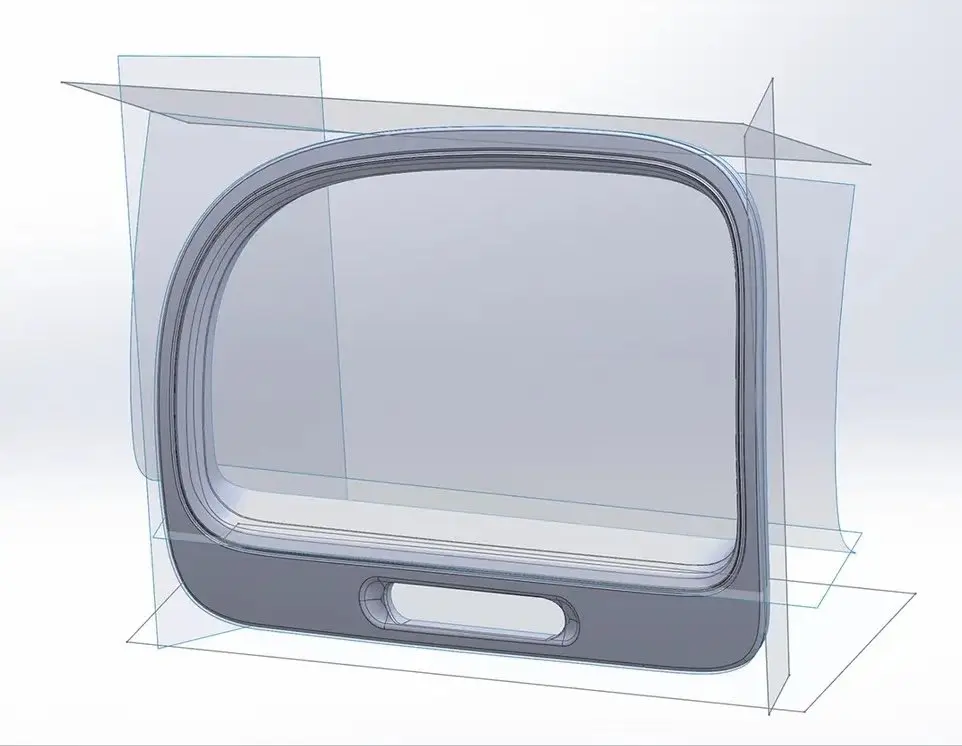
수동 다시 그리기
보스, 구멍, 포켓 같은 간단한 형상의 경우 일반적으로 스캔 모델을 참조하여 형상을 다시 그리는 것이 가장 빠르고 정확합니다. 리버스 엔지니어링 소프트웨어를 사용하면 스캔의 평평한 표면에 맞춰 정렬된 스케치 평면을 생성하고 스캔 메시에서 단면을 추출하여 원래 개체와 같은 모양을 생성하는 데 도움이 됩니다.
6. 새 개체 통합
스캔이 솔리드로 변환되면 다른 솔리드 본체에서 스캔을 빼서 원래 부품을 단단히 고정하는 지그를 만들 수 있습니다.
새로운 게이지 구성 요소의 디자인은 또한 반자동 표면 처리로 추출된 곡선을 사용하여 스캔 치수를 참조합니다.
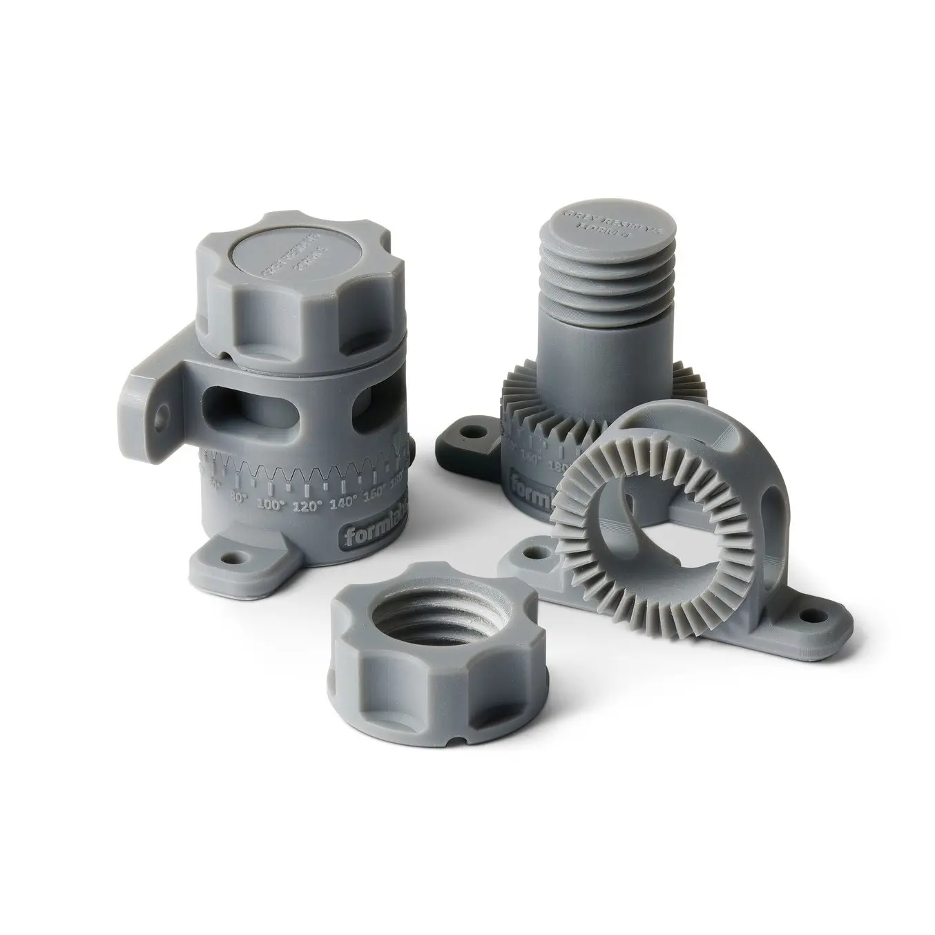
7. 새로운 디자인 3D 프린팅
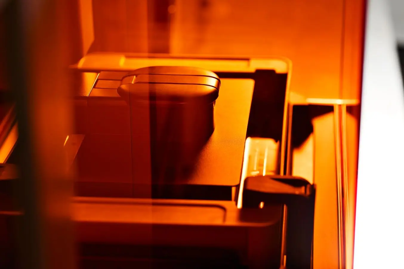
Rigid 4000 Resin으로 프린팅된 최종 3D 프린팅 조립 지그.
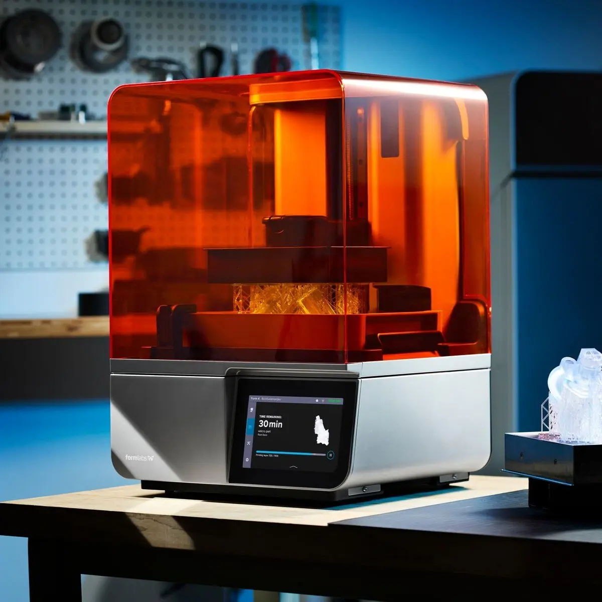
Formlabs 광경화성 수지 조형 방식(SLA) 3D 프린터로 지그를 프린팅하면 엔지니어링 등급 3D 스캐너의 출력에 필적할만큼 정확도가 높은 결과물을 얻을 수 있습니다. Formlabs는 다양한 응용 분야를 위한 광범위한 엔지니어링 3D 프린팅 수지 를 제공합니다.
이러한 단계가 완료되면 3D 프린트된 지그를 사용하여 새 게이지를 OEM 통풍구에 조립할 수 있습니다.
리버스 엔지니어링과 3D 프린트를 결합한 애플리케이션
리버스 엔지니어링은 종종 새로운 디자인을 기존 컴포넌트로 조립하기 위한 기초로 사용됩니다. 모든 관계형 객체를 모델링하지 않으면 CAD에서 어셈블리에서 발생할 수 있는 모든 잠재적 문제를 파악하기 어려울 수 있습니다. CAD에서 먼저 파트를 리버스 엔지니어링하려고 하면 많은 비용이 드는 시행착오를 겪을 수 있습니다. 3D 프린트를 사용하면 리버스 엔지니어링된 설계를 실제 공간에서 빠르게 테스트하고 반복할 수 있어 문제를 훨씬 쉽게 파악할 수 있습니다.
대규모 디자인 변경 외에도 측정 오류로 인해 발생할 수 있는 끼워맞춤 문제를 인식하는 것이 중요합니다. 대상 물체에 언더컷, 매우 얇은 보스(표면 위로 솟아오른 부분) 또는 스캔하기 어려운 깊은 포켓이 있는 경우, CAD에서 누락된 영역을 채우기 위해 추측을 사용해야 할 수 있습니다. 프린트된 프로토타입을 물리적으로 조립하면 새로운 수정 사항이나 스캔으로 인한 측정 오류 등 디자인에서 발생할 수 있는 공간적 충돌을 빠르게 찾아 해결할 수 있습니다.
엔지니어링 및 제조
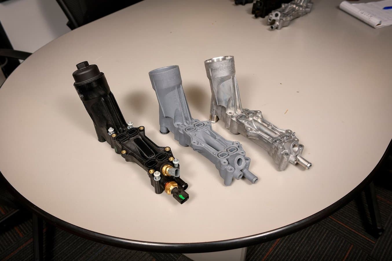
많은 자동차 소유주들이 고장을 겪은 엔진 컴포넌트이며, 여기에 보이는 것은 도먼의 재설계 과정에서 제작한 반복 설계품입니다.
Dorman사가 자동차 OEM 분야와 보조를 맞추는 데 도움이 된 3D 프린팅
Dorman Products는 애프터마켓 자동차 부품 제조업체입니다. Dorman사가 취급하는 제품은 키 포브와 기본 엔진 부품부터 복잡한 전자 모듈과 대형 트럭용 부품에 이르기까지 다양합니다.도먼사는 OEM 부품의 고장을 분석하고 제품을 리버스 엔지니어링하여, 경우에 따라서는 설계를 완전히 재고하고 개선합니다.
Form 3+로 프린트된 다양한 버전의 흡기 매니폴드.
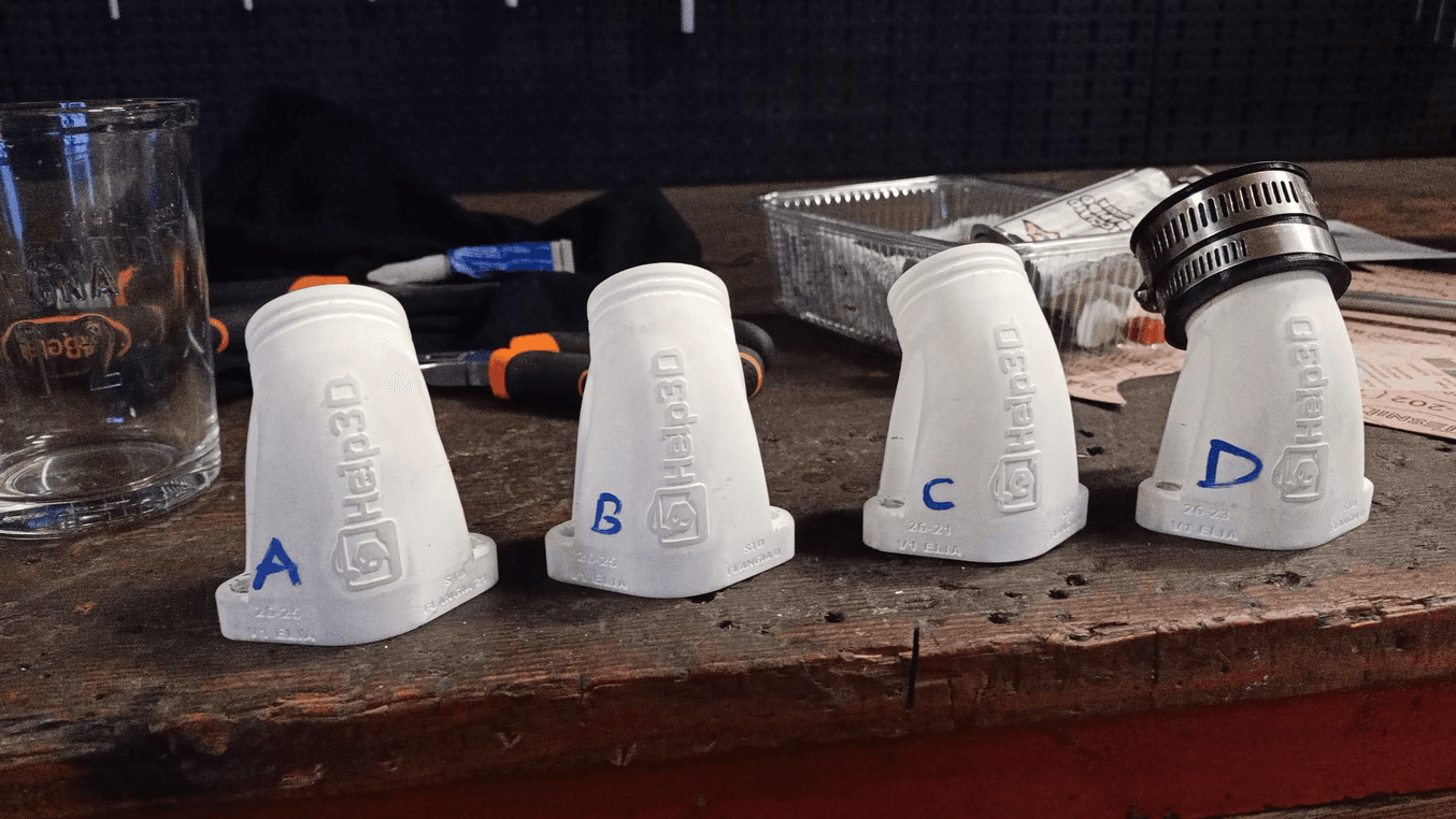
모터스포츠를 위한 내열성 최종 사용 부품 및 예비품 제작
Help3D 의 창립자인 안드레아 피라치니는 Formlabs 3D 프린터를 사용하여 12 폴리치 이탈리안 컵 챔피언십에서 자신이 타는 피트 바이크의 흡기 매니폴드를 리버스 엔지니어링했습니다. 프레임과 기화기가 있는 4행정 엔진(2밸브) 엔진을 스캔하여 매니폴드의 크기를 정확하게 정한 다음 기화기가 프레임이나 배기 시스템에 충돌하지 않도록 배치하는 데 도움이 되었습니다.
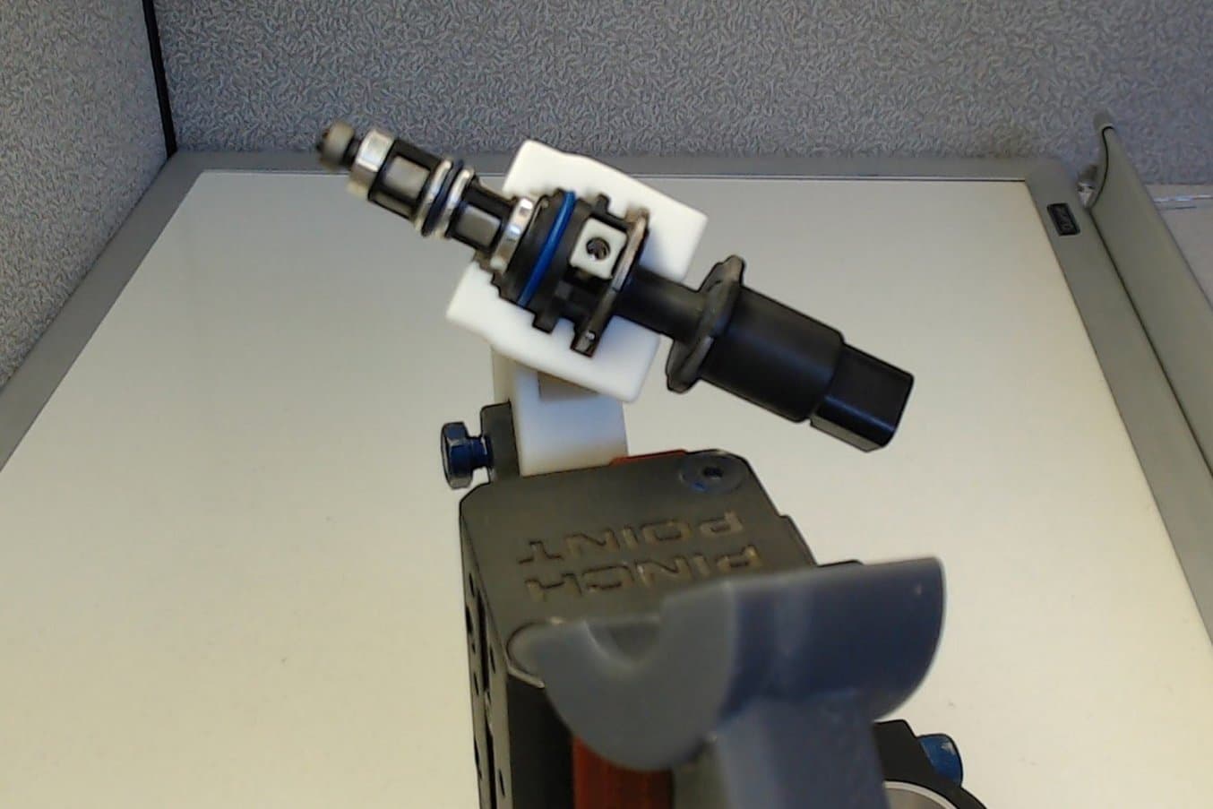
공압 실린더 어셈블리, 연료 인젝터를 고정하는 3D 프린팅 그리퍼로 완성되었습니다.
픽 앤 플레이스 로봇을 위한 맞춤형 연료 인젝터 그리퍼 3D 프린팅
STS Technical Group은 기술 설계 및 엔지니어링 과제에 대해 고객과 협력합니다. 픽 앤 플레이스 로봇용 연료 인젝터 그리퍼를 설계하기 위해 이들은 Creaform 레이저 3D 스캐너와 VX Elements 모델링 소프트웨어를 사용하여 연료 인젝터의 가상 3D 스캔을 통해 그리퍼 설계에 도움을 받았습니다. 스캔을 통해 연료 인젝터의 모든 간격, 실린더, 개구부를 지루하게 측정할 필요 없이 복잡한 디테일이 담긴 이미지를 얻을 수 있었습니다.
맞춤형 인체공학
장시간 인체로 쥐거나 만져야 하는 제품일수록 인체공학적인 끼워맞춤의 중요성은 더욱 커집니다. 몇 분 동안은 괜찮았던 끼워맞춤이 몇 시간이 지나면 불편해질 수 있으며, 인체공학적으로 부적절하면 반복적인 긴장 부상으로 이어질 수도 있습니다.
인체공학 및 맞춤형 제품 제작에 있어 3D 프린터와 스캐너는 상호 보완적인 도구입니다. 3D 프린터는 고가의 수작업 없이도 보조기, 핸드헬드 그립, 안경 등 주문에 따라 개별화된 컴포넌트와 제품을 생산할 수 있습니다.
올바른 도구만 있다면 유기적 형상을 리버스 엔지니어링하는 것은 공차가 엄격한 기계식 파트를 리버스 엔지니어링하는 것보다 의외로 간단합니다. Solidworks용 Geomagic의 '자동 표면' 기능은 스캔(STL)에서 유기 표면을 가진 매끄러운 CAD 표면을 생성합니다. 자동 표면 처리 기능은 노이즈가 많거나 거친 표면을 제거하여 인상을 제품으로 변환할 때 유용한 기능입니다.
솔리드 CAD 툴로 편집할 수 있는 서피스를 확보하면 볼트 구멍 패턴, 마운팅 플레이트, 기타 끼워맞춤 등 파트가 다른 일반 컴포넌트와 인터페이스할 수 있는 기능을 쉽게 빼거나 추가할 수 있습니다.
첨단 보철물의 접근성을 개선한 PSYONIC
PSYONIC의 어빌리티 핸드는 신속 프로토타이핑, 금형 제작, 최종 사용 파트를 모두 3D 프린팅으로 제작하는 상지 의족입니다. 수석 기계 엔지니어 제임스 오스틴은 "때때로 다른 회사의 제품과 호환되어야 하는 파트가 있는데, 의료 업계의 많은 제품과 마찬가지로 엄청난 비용이 들지만 이러한 파트를 구매해야 하는 경우도 있습니다. 사실 크기가 작은 파트 정도는 모양과 형태를 꽤 쉽게 리버스 엔지니어링해서 간단하게 자체 생산할 능력이 있었습니다."라고 후일담을 들려주었습니다.
리버스 엔지니어링에 적합한 도구
파트 리버스 엔지니어링 시작의 첫 번째 단계는 요구 사항에 가장 적합한 3D 스캐너를 찾는 것입니다. 고정밀 3D 프린트 작업의 보완적인 3D 스캐너를 소개합니다.
광경화성 수지 조형 방식(SLA) 및 선택적 레이저 소결 방식(SLS) 3D 프린팅 기술을 살펴보거나 무료 샘플 파트를 요청하여 Formlabs 소재를 직접 평가해 보세요.
귀사의 비즈니스에 가장 적합한 3D 프린팅 솔루션이 무엇인지 잘 모르시겠습니까? 1:1 상담을 예약하여 옵션을 비교하고, ROI를 평가하고, 테스트 프린팅을 해보는 등 다양한 작업을 직접 해보세요.