Los materiales compuestos, como los plásticos reforzados con fibra de carbono, son materiales muy versátiles y eficientes que impulsan la innovación en varios mercados, desde el sector aeroespacial a la sanidad. Obtienen mejores resultados que materiales como el acero, aluminio, la madera o el plástico y permiten la fabricación de productos ligeros de alto rendimiento.
En esta guía, aprenderás las bases de la fabricación de piezas de fibra de carbono, además de los diferentes métodos de fabricación, y cómo puedes usar una impresora 3D para reducir costes y ahorrar tiempo. También existen materiales compuestos que se pueden imprimir en 3D directamente, como el Nylon 11 CF Powder, un material con relleno de fibra de carbono perfecto para aplicaciones que requieren tanto una gran rigidez como una resistencia superior. Cuando se imprime en la impresora Fuse 1+ 30W de Formlabs, el Nylon 11 CF Powder produce piezas ligeras y rígidas con estabilidad estructura y térmica, que sean capaces de soportar impactos repetidamente.
Solicita una pieza de muestra gratuita del Nylon 11 CF Powder
Comprueba por tu cuenta la calidad del nylon con relleno de fibra de carbono. Enviaremos una pieza de muestra gratuita a tu lugar de trabajo.
¿Qué son los materiales compuestos?
Un material compuesto es una combinación de dos o más componentes, en la que la mezcla tiene características diferentes a las de los componentes por separado. La combinación suele mejorar las propiedades de ingeniería, como la fuerza, la eficiencia o la durabilidad. Los materiales compuestos están hechos de un refuerzo (formado por fibras o partículas), que se mantiene unido mediante una matriz (de polímero, metal o cerámica).
Los polímeros reforzados con fibras dominan el mercado y han fomentado el crecimiento de nuevas aplicaciones en varios sectores. Entre ellos, la fibra de carbono es un compuesto muy utilizado, especialmente para la fabricación de aviones, coches de carreras y bicicletas, ya que es tres veces más resistente y firme que el aluminio, pero un 40 % más ligera. Está formada por fibra de carbono reforzada, enlazada con resina epoxi.
Las fibras pueden tejerse unidireccionalmente y alinearse estratégicamente para crear resistencia respecto a un vector. Las fibras tejidas de forma cruzada pueden usarse para crear resistencia en múltiples vectores y también son responsables del aspecto acolchado de las piezas compuestas. Es común que las piezas se produzcan con una combinación de ambos métodos. Hay varios tipos de fibras disponibles, que incluyen:
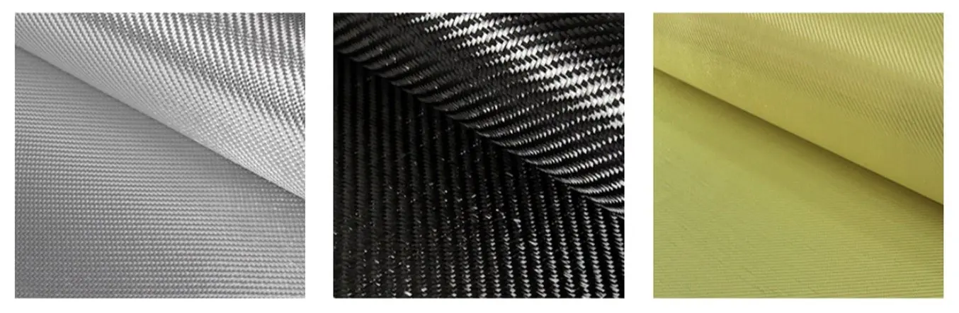
| Fibra de vidrio | Fibra de carbono | Fibra de aramida (kevlar) |
|---|---|---|
| La fibra más popular Ligera, con resistencia moderada a la tracción y a la compresión Coste bajo, fácil de trabajar | La relación de resistencia y rigidez por peso más alta del sector (resistencia a la rotura por tracción, a la compresión y a la flexión) Más cara que otras fibras | Resistencia más alta a impactos y a la abrasión que la fibra de carbono Baja resistencia a la compresión Difícil de cortar o mecanizar |
Estas fibras se unen con resina para crear un material compuesto rígido. Aunque se pueden usar cientos de tipos de resinas, estas son las más populares:
| Resina | Ventajas | Inconvenientes | Curado |
|---|---|---|---|
| Resina epoxi | Máxima resistencia a la rotura Peso más ligero Vida útil más larga | Lo más caro Sensible a las proporciones de la mezcla y a las variaciones de temperatura | Usa un endurecedor específico (sistema de dos partes) Algunos epoxis requieren calor |
| Poliéster | Fácil de usar (más popular) Resistente a los rayos UV Coste mínimo | Baja tenacidad y resistencia a la corrosión | Se cura con un catalizador (PMEC) |
| Viniléster (éster de vinilo) | Combina el rendimiento del epoxi con el coste del poliéster Mejor alargamiento y mejor resistencia a la corrosión y a las temperaturas extremas | Menos resistente que el epoxi y más caro que el poliéster Vida útil limitada | Se cura con un catalizador (PMEC) |
Reserva una consulta gratuita
Ponte en contacto con nuestros expertos en impresión 3D para tener una consulta personalizada y encontrar la solución adecuada para tu negocio, recibir un análisis de rentabilidad de la inversión, realizar impresiones de prueba y mucho más.
Tres métodos para crear piezas de fibra de carbono
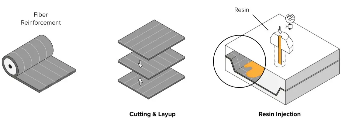
Fabricar polímeros reforzados con fibras, como las piezas de fibra de carbono, es un proceso que requiere habilidad y trabajo manual, y que se usa tanto en la producción de piezas únicas y la producción por lotes. Los tiempos de los ciclos varían desde una hora a 150 horas según el tamaño y complejidad de la pieza. Lo típico es que en la fabricación con polímeros reforzados con fibras, las fibras rectas y continuas se unan a la matriz para formar capas individuales que se laminen capa por capa en la pieza final.
Las propiedades de los compuestos se deben tanto a los materiales como al proceso de laminación: la forma en que las fibras se incorporan influye mucho en el rendimiento de la pieza. A las resinas termoendurecibles se les da forma junto con el refuerzo dentro de una herramienta o molde para formar un producto robusto. Existen diversas técnicas de laminación, que pueden dividirse en tres tipos principales:
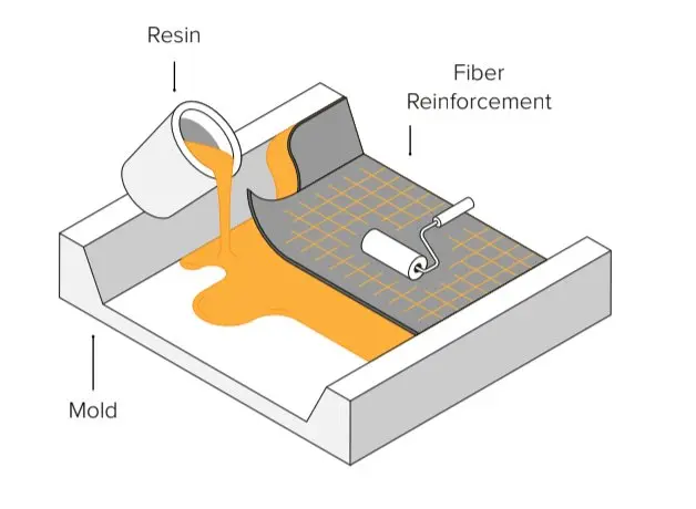
1. Colocación en húmedo
En la colocación en húmedo, la fibra se corta y se coloca en el molde. A continuación, se aplica la resina con un cepillo, rodillo o pistola pulverizadora. Este método es el que requiere más habilidad para crear piezas de alta calidad, pero también es el proceso de trabajo menos caro con los requisitos más bajos para empezar a hacer tus propias piezas de fibra de carbono. Si eres principiante en la fabricación de piezas de fibra de carbono y aún no cuentas con el equipo adecuado, te recomendamos que empieces con la laminación en húmedo a mano.
Mira el vídeo para ver cómo funciona el proceso de colocación en húmedo para laminar piezas de fibra de carbono.
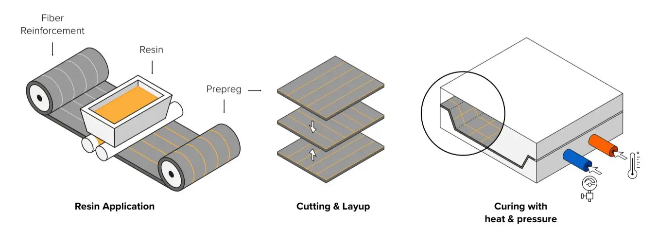
2. Laminación preimpregnada
Con la laminación preimpregnada, la fibra se impregna de resina con antelación. Las láminas preimpregnadas se guardan en un ambiente frío para evitar que se curen. A continuación, las capas se curan en el molde bajo calor y presión en un autoclave. Se trata de un proceso más preciso y repetible porque se controla la cantidad de resina, pero también es la técnica más cara que suele utilizarse en aplicaciones de alto rendimiento.
3. Moldeo por transferencia de resina (RTM)
Con el moldeo RTM, la fibra seca se inserta en un molde de dos partes. El molde se cierra con abrazaderas antes de forzar la resina a entrar a alta presión en la cavidad. Normalmente, este proceso es automático y se usa para la fabricación de alto volumen.
Cómo crear moldes para la fabricación de piezas de fibra de carbono usando la impresión 3D
Ya que la calidad del molde afecta directamente a la calidad de la pieza final, crear las herramientas es un aspecto fundamental de la fabricación con polímeros reforzados con fibras. La mayoría de los moldes se producen a partir de cera, espuma, madera, plástico o metal mediante el mecanizado CNC o métodos artesanales. Mientras que las técnicas manuales requieren mucho trabajo manual, el mecanizado CNC sigue siendo un proceso de trabajo complejo y lento (especialmente para geometrías intrincadas) y la externalización suele tener un coste elevado, con un largo tiempo de entrega. Ambas opciones requieren trabajadores cualificados y ofrecen poca flexibilidad para realizar iteraciones en los diseños y modificar los moldes.
La fabricación aditiva ofrece una solución para producir de forma rápida y económica moldes y patrones para fabricar piezas de fibra de carbono. El uso de herramientas poliméricas en el proceso de fabricación no deja de crecer. Reemplazar las herramientas de metal con piezas de plástico impresas in situ es una forma rentable y potente de reducir el tiempo de producción al mismo tiempo que se expande la flexibilidad de los diseños. Los ingenieros ya trabajan con piezas impresas en 3D en resina polimérica para fabricar sujeciones con guía y fijaciones que sirven de apoyo a métodos como el enrollado de filamentos o la colocación automática de fibras. Asimismo, se emplean moldes y troqueles impresos en tiradas cortas en el moldeo por inyección, el termoformado o el conformado de chapa para producir remesas de bajo volumen.
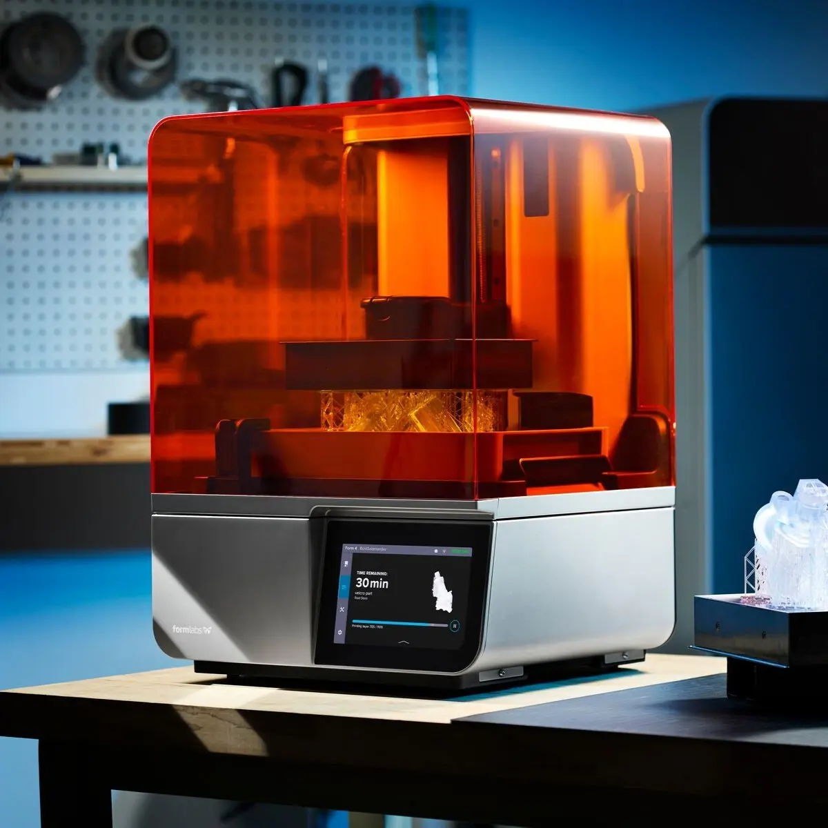
La impresión 3D de escritorio in situ no requiere mucho equipamiento y reduce la complejidad del proceso de trabajo. Las impresoras de resina de escritorio profesionales como la Form 4 son asequibles y fáciles de integrar en los procesos de trabajo, y su número se puede expandir rápidamente a medida que crezca la demanda. Fabricar herramientas y moldes grandes también es posible con impresoras 3D de gran formato como la Form 4L.
La tecnología de impresión 3D por estereolitografía (SLA) crea piezas con un acabado de la superficie muy liso, lo que es esencial para los moldes de laminación de fibra de carbono. Permite crear geometrías complejas con un gran nivel de precisión. Además, el catálogo de resinas de Formlabs tiene materiales de ingeniería con propiedades mecánicas y térmicas que encajan bien con la fabricación de moldes y patrones.
Los moldes impresos en 3D para la fabricación de piezas de fibra de carbono pueden reducir los costes y los tiempos de producción.
Para una producción a pequeña escala, los ingenieros pueden imprimir el molde directamente a bajo coste y en solo unas horas sin tener que tallarlo a mano o lidiar con los engorros del equipamiento de CNC: el software de CAM, la configuración de la máquina, las sujeciones de las piezas, el utillaje y la evacuación de las virutas. La mano de obra y el tiempo de producción para la fabricación del molde se reducen drásticamente, lo que permite realizar iteraciones rápidas del diseño y personalizar las piezas. Incluso se pueden obtener moldes de formas complicadas con detalles precisos que serían difíciles de fabricar de forma tradicional.
Recomendaciones para la arquitectura y el diseño de los moldes
Al diseñar tu molde, ten en cuenta qué cosas se imprimen y se moldean con éxito. Para crear diferentes tipos de geometrías se utilizan distintas arquitecturas para los moldes:
- Molde de una pieza en bolsa de vacío: Se utiliza para piezas que necesitan una cara de clase A, que quiere decir un acabado brillante. El relieve puede ser positivo (saliente o convexo) o negativo (deprimido o cóncavo), dependiendo de qué cara debería ser de clase A. Una cara es la superficie del molde, mientras que la otra cara es la superficie que da a la bolsa de vacío.
- Molde de dos piezas en el moldeo por compresión: Se utiliza para piezas en las que ambas caras de la pieza deben ser de clase A. Ambas caras son superficies que dan al molde.
- Moldeo con vejiga en el moldeo a presión: Se utiliza para geometrías complejas en las que no se puede utilizar una bolsa de vacío o molde de compresión al no poder desmoldar la pieza. Una cara es la superficie del molde, mientras que la otra es la que da a la vejiga.
- Patrón de molde para crear un molde negativo: Se utiliza cuando se desean múltiples moldes para incrementar la producción. Se pueden fabricar múltiples moldes a partir de un único patrón.

Añade un ángulo de desmoldeo: Un ángulo de desmoldeo positivo de dos o tres grados facilitará el proceso de separar el molde de la pieza y prolongará la vida del molde, especialmente si se trata de un molde rígido. Sin embargo, utilizar un material flexible de impresión 3D como la Tough 1500 Resin puede permitirte crear piezas sin un ángulo de desmoldeo e incluir geometrías difíciles que no podrían separarse de un molde rígido en condiciones normales. Prepara un radio mínimo adecuado para el grosor de tu material: esto ayuda a las fibras a alinearse en los rincones y al mismo tiempo evita la entrada de aire, además de ayudar a crear piezas de calidad repetibles. No crees esquinas con ángulos pronunciados ni caras demasiado cercanas, ya que es más fácil trabajar con geometrías suaves y curvas que con geometrías afiladas y cuadriculadas.
Prepara un radio mínimo adecuado para el grosor de tu material: Esto ayuda a las fibras a alinearse en los rincones y al mismo tiempo evita la entrada de aire, además de ayudar a crear piezas de calidad repetibles. No crees esquinas con ángulos pronunciados ni caras demasiado cercanas, ya que es más fácil trabajar con geometrías suaves y curvas que con geometrías afiladas y cuadriculadas.

Incluye pernos de posicionamiento y muescas para moldes que requieran una alineación precisa. Una de las grandes ventajas de la impresión 3D es que hace posible que la geometría de la alineación sea compleja y ayuda a fabricar diseños orientados a un posicionamiento más sencillo.
Incluye una extensión de la superficie: el material sobrante de la superficie extendida se cortará para dibujar una línea de recorte precisa. La impresión 3D permite imprimir esta extensión sin necesidad de crear una rebaba manualmente.
Añade líneas de recorte: la impresión 3D permite incorporar elementos de refinamiento, como guías para brocas, líneas para realizar un recorte manual o raíles para guiar a las máquinas de fresado.
Otras buenas prácticas:
- Imprime con la altura de capa más pequeña posible para optimizar la resolución y el paso de desmoldeo.
- Evita colocar soportes en las superficies de moldeo para obtener un mejor acabado de la superficie.
- Utiliza un agente de desmoldeo: esto es necesario para realizar el proceso de desmoldeo.
- Para evitar la inclusión de aire en las piezas: después de agitar y mezclar la resina, espera dos minutos para que esta se asiente y el aire salga de ella. Repite el proceso después de aplicar la primera capa de resina. Si quedan pequeñas burbujas de aire, se pueden pulir y sellar en el posacabado.
Caso de estudio: La Universidad Técnica de Berlín imprime en 3D moldes de fibra de carbono
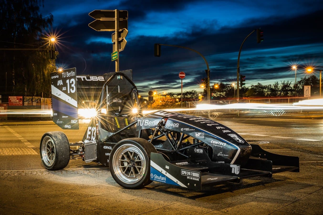
Formula Student es una competición anual de diseño de ingeniería en la que equipos de estudiantes de todo el mundo construyen y conducen coches de tipo fórmula. El equipo de Formula Student de la Universidad Técnica de Berlin (FaSTTUBe) es uno de los más grandes; entre 80 y 90 estudiantes han estado desarrollando nuevos coches de carreras cada año desde 2005.
El equipo de Formula Student de la Universidad Técnica de Berlin (FaSTTUBe) está construyendo tres vehículos para la competición anual de Formula Student.
El equipo de FasSTTUBe tiene acceso a casi toda la gama de tecnologías de fabricación y utiliza la impresión 3D con tres fines:
- Prototipos: imprimen prototipos de diferentes piezas como las fijaciones de la barra antivuelco o partes de la batería de alta tensión.
- Moldes de fibra de carbono impresos en 3D: el equipo imprimió una docena de moldes para fabricar piezas que no podrían haberse hecho de otra manera.
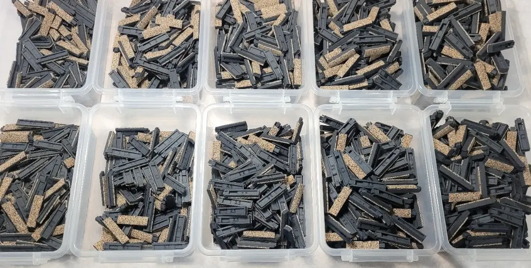
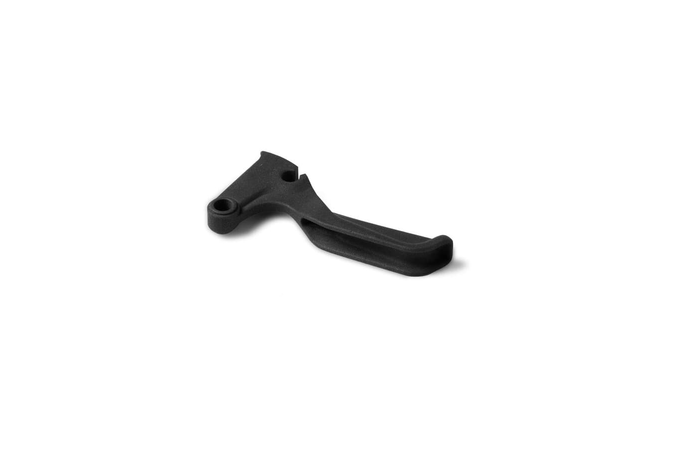
- Piezas de uso final: unas 30 piezas de los vehículos finales se imprimen directamente en 3D; desde soportes para botones, palancas de cambio del volante, hasta mangueras y conectores de sensores de los sistemas de refrigeración.
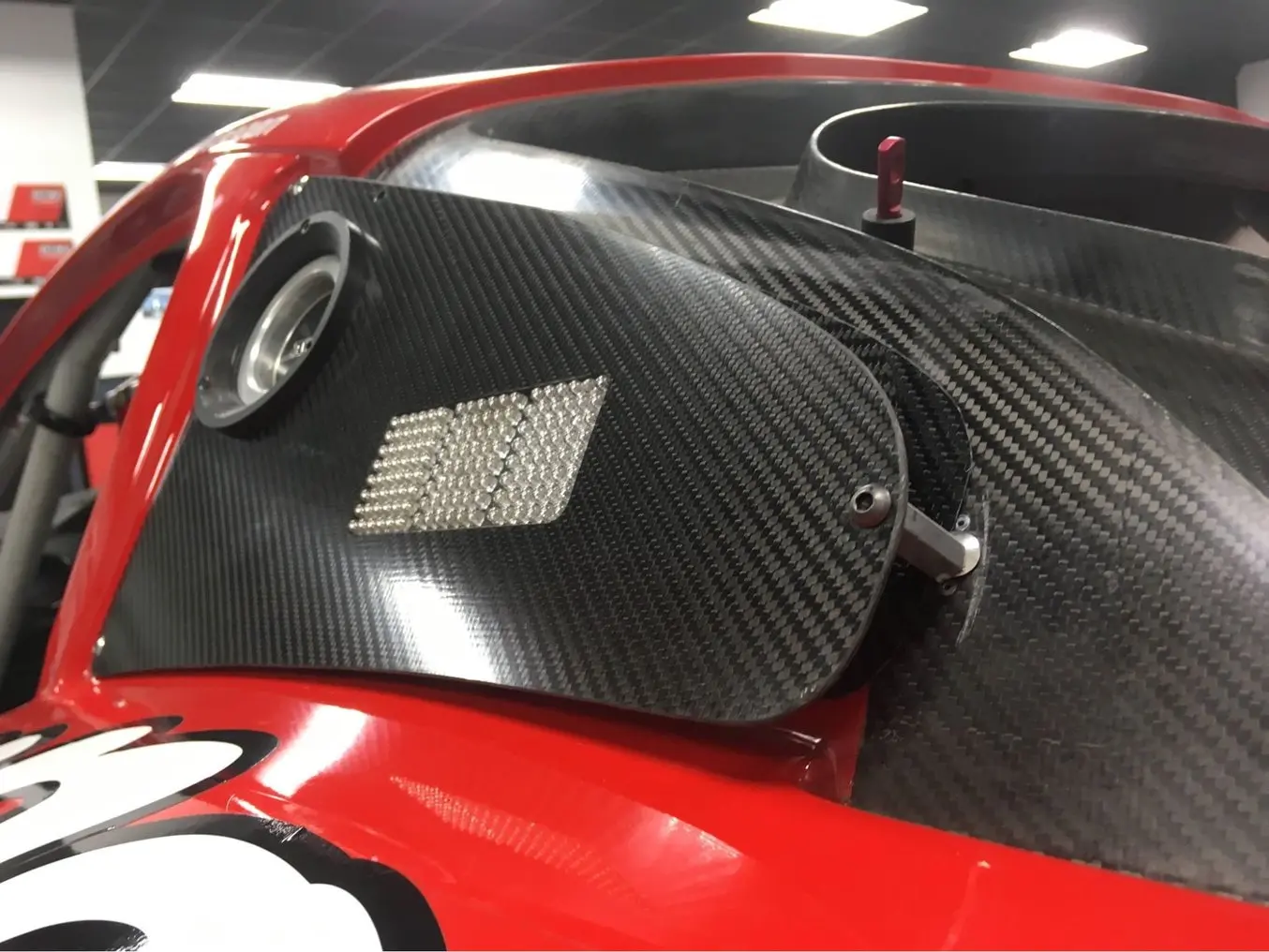
En este caso de estudio, examinamos los detalles del proceso de moldeo que utilizaron para fabricar el bastidor y las asas del volante con fibra de carbono.
Reducir el peso es esencial en la construcción de coches de competición. Habría sido posible imprimir las asas del volante huecas para aligerar las piezas, pero no serían lo suficientemente resistentes como para soportar el agarre del conductor. La fibra de carbono es un material excelente para reducir el peso al mismo tiempo que se mantiene o incluso se incrementa la resistencia. Para poder fabricar este año la pieza con fibra de carbono, Felix Hilken, el director de aerodinámica y fabricación con carbono, elaboró un proceso de trabajo utilizando moldes impresos en 3D para la laminación con colocación en húmedo.
Equipamiento necesario:
- Impresora 3D SLA de Formlabs con la Tough 1500 Resin
- Fibra de carbono: tres capas de 200 g, 3K y 0,3 mm, con un patrón de tejido de sarga
- Agente de desmoldeo: cera y alcohol polivinílico
- Resina epoxi de gran resistencia
- Cepillo y tijeras
- Bolsa de vacío, bomba de vacío y manta de aireación/absorción
- Papel de lija

1. Diseña el molde
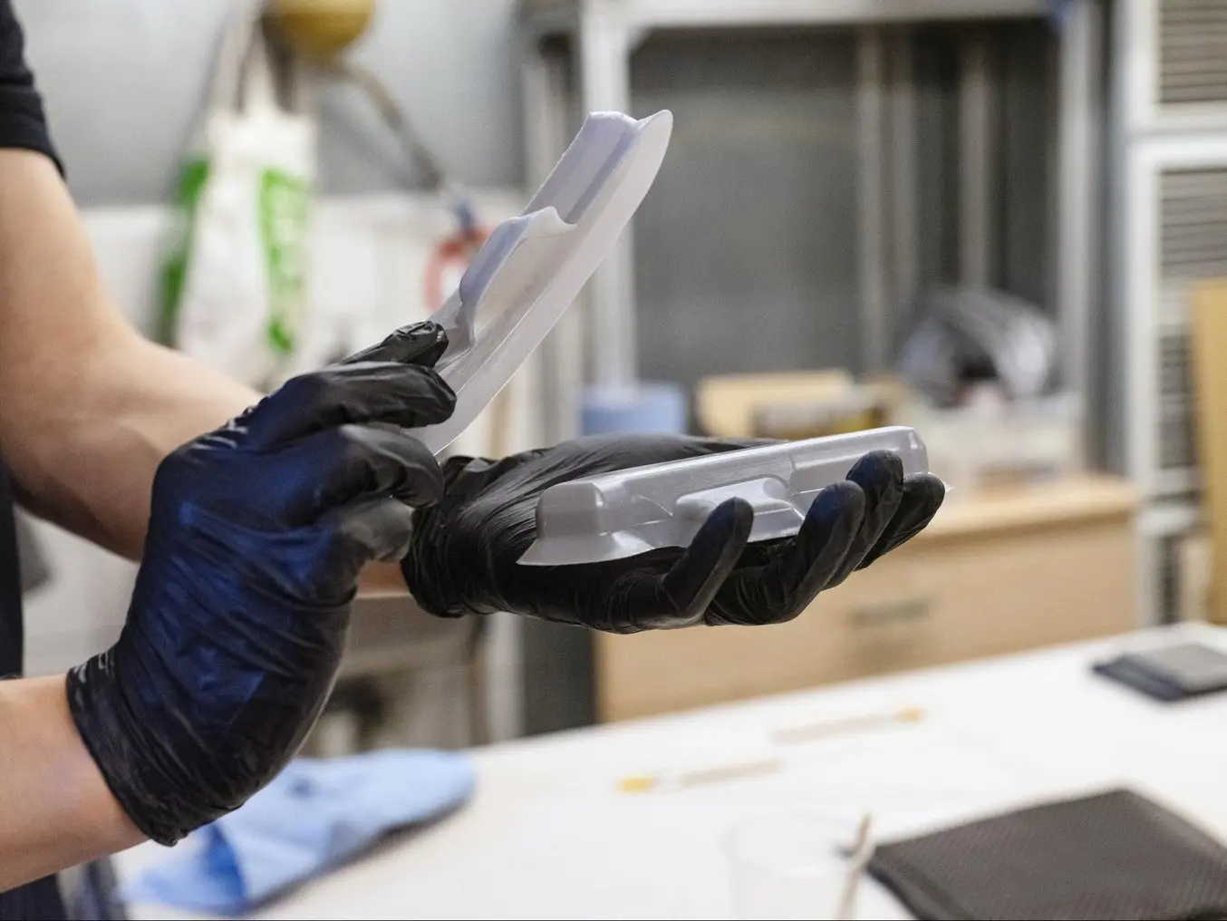
El asa se fabricó en dos mitades con el fin de poder desmoldar la pieza. Para cada mitad del asa, Felix diseñó un molde de dos piezas que incluía elementos difíciles de fabricar sin la impresión 3D, como:
- Detalles precisos como radios internos ajustados, superficies de barrido o superficies con radios variables
- Bordes redondeados ajustados que no se podían desmoldar de un molde de aluminio
- Muescas para ubicar los puntos de perforación, porque el posicionamiento de la pieza es importante

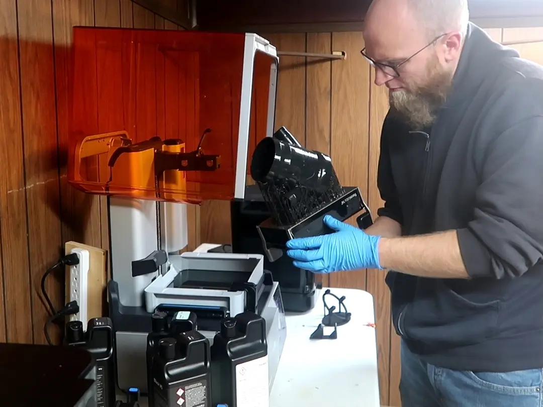
2. Imprime el molde en 3D
El equipo imprimió en 3D los moldes en la impresora de la serie Form con la Tough 1500 Resin, a una altura de capa de 50 micras. Las impresiones se lavaron durante dos períodos de 10 minutos en alcohol isopropílico y se poscuraron durante 60 minutos a 70 ºC. Eligieron la Tough 1500 Resin porque ofrece un buen alargamiento y módulo; las piezas que se imprimen con este material pueden doblarse considerablemente y volver rápidamente a su forma original. Es una propiedad mecánica deseada para evitar que se rompa el molde durante el desmoldeo.

3.1 Laminado a mano: Aplica el agente de desmoldeo
Aplica el agente de desmoldeo para facilitar la separación de la pieza del molde. Este primer paso es crucial, ya que si algunas superficies no quedan cubiertas, la pieza no se separará del molde.
- Cubre con cera (opcional, pero recomendado)
- Cubre con alcohol polivinílico

3.2 Mezcla la resina y el endurecedor
Mezcla la resina con el endurecedor. La proporción de la mezcla debe seguirse a rajatabla. Si la proporción se desvía de la proporción deseada incluso un porcentaje pequeño, la pieza quedará demasiado blanda o solo se curará parcialmente. Sigue atentamente las instrucciones del fabricante de la resina y lee la ficha de seguridad antes de su uso. En el caso de la resina que utilizó Felix, el proceso de polimerización comienza dos horas después de que se mezcle la resina, lo que deja dos horas para llevar a cabo la colocación.

3.3 Aplica la resina
Aplica resina con un cepillo en la cara positiva del molde.

3.4 Coloca la fibra de carbono
Coloca un tejido de fibra de carbono sobre la cara positiva del molde. Asegúrate de seguir todos los contornos. El equipo utilizó una fibra 3K (de 3000 hilos de grosor) para equilibrar el grosor y el precio del tejido. Se diseñó específicamente para seguir contornos complejos y que no tuviera hilos de soporte.

3.5 Aplica resina a la fibra de carbono
Aplica resina en el tejido de carbono y repite el proceso de colocación. La resina une las capas, formando el componente de matriz de las piezas y evitando que la fibra vuelva a alinearse. Felix utilizó tres láminas de fibra de carbono.

3.6 Aplica la resina final al negativo
Aplica una última capa de resina en la parte negativa del molde y presiona las dos mitades del molde la una contra la otra para evitar que se formen burbujas de aire o que permeen a través de las fibras.

3.7 Retira el material sobrante
Corta el material sobrante con unas tijeras.

3.8 Realiza el curado
Realiza un curado de 48 horas en una bolsa de vacío. Durante este proceso de polimerización, la bolsa de vacío extrae el aire y presiona las láminas de fibra de carbono contra el molde a temperatura ambiente para eliminar la resina sobrante. Esto asegura que la proporción volumétrica de resina a fibras sea la deseada, para que la rigidez de la pieza sea la adecuada.

4. Posacabado y acabado
Realiza el acabado: lija todos los bordes. Para limpiar el molde tras el proceso, Felix lo sumergió en agua durante unos 30 minutos para disolver el alcohol polivinílico y después usó papel de lija de grano 1500 para eliminar los restos de resina.
Resultados
Al utilizar fibra de carbono, el equipo redujo el peso de la carcasa del volante de 120 g a 21 g, y pudieron dar al diseño geometrías que serían extremadamente difíciles de fabricar de forma tradicional. "Lo bueno de la impresión 3D es que una forma compleja es igual de fácil de fabricar que una sencilla, requiere la misma cantidad de trabajo y de equipo", dice Felix.
Sin la impresión 3D, el equipo habría tenido que externalizar el fresado CNC de un molde de aluminio, lo que es caro, tarda mucho en realizarse y requiere herramientas especializadas. "Tendría que mecanizar el molde mediante CNC, conseguir herramientas especializadas y esperar a tener un turno en la máquina. Pero ni siquiera podría hacer esta geometría. Concretamente, algunas de las esquinas pequeñas. Tendría que utilizar un diseño que no tuviera ningún tornillo, para que el posicionamiento no fuera importante para la pieza".
Según sus cálculos, un molde impreso con la Tough 1500 Resin de Formlabs se podría utilizar para fabricar alrededor de diez piezas. Dado que se trata de un proceso manual, depende de lo meticuloso que sea el operario: el molde puede romperse durante el proceso de separación. No obstante, es posible utilizar múltiples moldes impresos en 3D para aumentar la producción. Otra solución para alargar la vida útil del molde sería darle soporte con un molde genérico metálico. Un inserto impreso en 3D lleva el peso de la geometría, mientras que un molde metálico de apoyo ayuda a que mantenga su forma. Esto se podría fabricar con una máquina simple de fresado manual.
| Molde de mecanizado CNC externalizado | Molde impreso en 3D in situ | |
|---|---|---|
| Equipamiento | Fibra de carbono, resinas, herramientas, bolsa de vacío | Fibra de carbono, resinas, herramientas, bolsa de vacío, impresora 3D, Tough 1500 Resin |
| Tiempo de producción del molde | 4-6 semanas | 2 días |
| Costes de mano de obra | 0 $ | 300 $ |
| Costes de material | 0 $ | 10 $ |
| Costes totales de producción del molde | 900 $ | 310 $ |
Caso de estudio: Piezas de fibra de carbono para automóviles de Panoz
DeltaWing Manufacturing crea piezas de materiales compuestos para la empresa Panoz, que se dedica al diseño y la fabricación de exclusivos coches deportivos de lujo hechos en Estados Unidos. Antes, para fabricar componentes de fibra de carbono, DeltaWing Manufacturing mecanizaba un patrón, laminaba o fundía un molde con él y daba el acabado al molde antes de aplicar el proceso de preimpregnación para laminar la pieza de fibra de carbono.
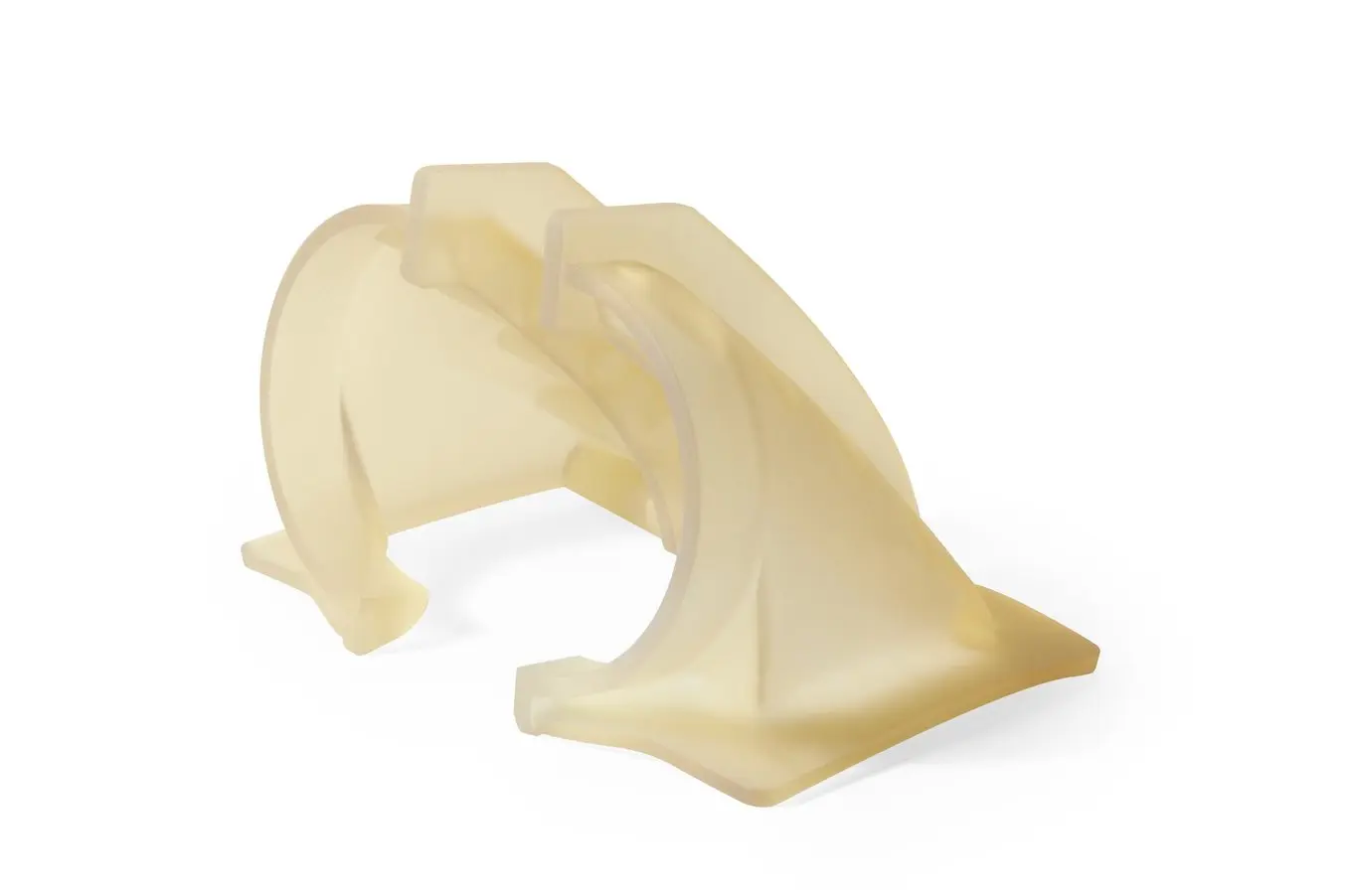
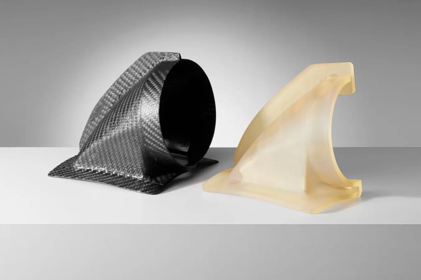
En los últimos años, han empezado a utilizar piezas impresas en 3D in situ como parte intermedia de este proceso. Panoz necesitó seis unidades de un conducto de aire de guardabarros para un coche de carreras personalizado. Para reducir el trabajo manual y el tiempo de producción respecto a su técnica tradicional de creación de moldes, los ingenieros de DeltaWing Manufacturing decidieron imprimir en 3D directamente el molde y aplicarlo en su proceso de preimpregnación.
Equipamiento necesario:
- Impresora 3D SLA de Formlabs con la High Temp Resin
- Fibra de carbono: 4K, patrón bidimensional
- Agente de desmoldeo: alcohol polivinílico
- Cinta Kapton (de poliimida)
- Resina epoxi de gran resistencia
- Cepillo y tijeras
- Bolsa de vacío, bomba de vacío

1. Diseña el molde
El conducto se fabricó en dos piezas distintas en dos moldes diferentes, para facilitar la separación de la pieza final del molde, que se unieron posteriormente. Cada molde también se imprimió en dos piezas y se ensambló para que pudiera caber en el volumen de impresión de las impresoras de la serie Form. Sin embargo, esto no sería necesario con el mayor volumen de impresión que ofrece la impresora Form 4L. Las piezas se diseñaron para la fabricación aditiva, siguiendo las recomendaciones de diseño de los moldes.

2. Imprime el molde en 3D
DeltaWing imprimió los moldes con la High Temp Resin en una impresora de la serie Form, con una altura de capa de 100 micras. Esta resina fue la elegida porque tiene una temperatura de flexión bajo carga de 238 °C a 0,45 MPa, la más alta entre las resinas de Formlabs y una de las más altas entre las resinas del mercado.
La High Temp Resin puede soportar temperaturas de curado altas, muestra una buena rigidez para mantener su forma durante el procedimiento y ofrece un gran nivel de detalle que se trasladará a la pieza final. Formlabs recomienda lavar las impresiones de High Temp Resin con alcohol isopropílico durante 10 minutos, poscurarlas a 80 °C durante 120 minutos y después calentar las piezas durante 3 horas a 160 °C para obtener una mayor temperatura de flexión bajo carga.

3. Realiza la laminación preimpregnada
DeltaWing Manufacturing aplicó su proceso de preimpregnación habitual a los moldes impresos, utilizando una fibra de patrón bidimensional 4K (de 4000 hilos de grosor). Cada molde se cubrió con cinta Kapton para renovar la superficie con cada iteración de moldeo. La fibra se colocó en los moldes y a continuación, las piezas se colocaron en una bolsa de vacío y se curaron en un autoclave antes de desmoldarlas y recortarlas. Los moldes impresos toleraron un curado lento a 38 °C durante 10 horas o un curado rápido a 126 °C durante una hora sin sufrir daños. Las dos mitades del conducto de carbono se unieron en un paso final.
Finalización y resultados
El equipo sometió a ensayo seis iteraciones para un molde sin observar ninguna degradación reseñable. Estimamos que para un molde son posibles unas 10-15 iteraciones. Ya que se utilizan autoclaves para aplicar calor y presión durante el curado en el proceso de preimpregnación, el molde impreso solo puede soportar unas pocas iteraciones. Por consiguiente, este método no es recomendable para la producción de alto volumen, pero es un modo excelente de producir series cortas de piezas y piezas personalizadas en masa. Esto hace posible una amplia gama de usos como equipamiento deportivo de alto rendimiento, utillaje personalizado para el sector aeroespacial o prótesis personalizadas a medida de los pacientes en el sector sanitario.
Impresión 3D con fibra de carbono
Hay una gran demanda de procesos de trabajo que combinen la tenacidad, durabilidad y robustez de las piezas de fibra de carbono tradicionales con la agilidad, las posibilidades geométricas y la repetibilidad de la impresión 3D. Por lo tanto, no es sorprendente que haya muchas empresas de impresión 3D que ofrezcan impresión 3D de fibra de carbono, con los dos procesos actualmente disponibles siendo la impresión con fibras cortadas o fibras continuas.
Gracias a las fibras de carbono cortadas que usa, el Nylon 11 CF Powder para la Fuse 1+ 30W (una impresora 3D industrial de sinterizado selectivo por láser) permite a los fabricantes crear piezas tenaces, ligeras y resistentes al calor sin tener que depender de métodos tradicionales de recubrimiento de soldadura o mecanizado.
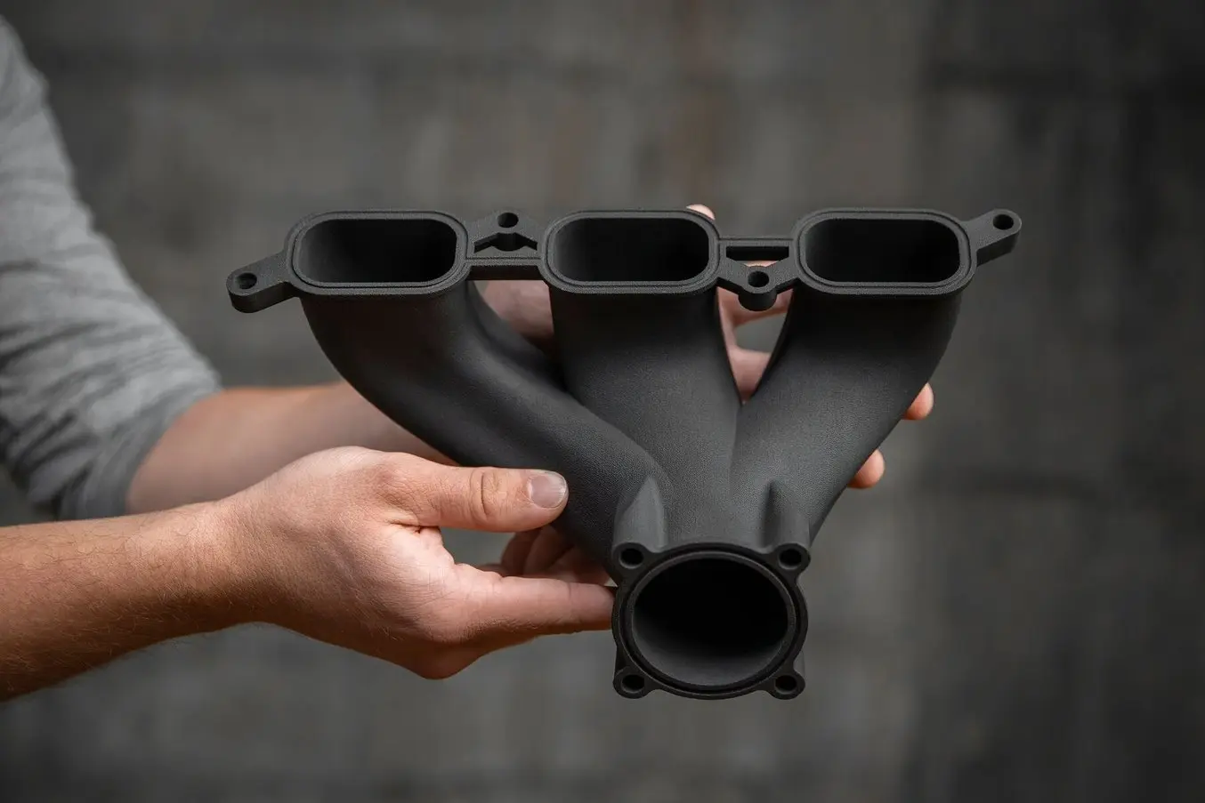
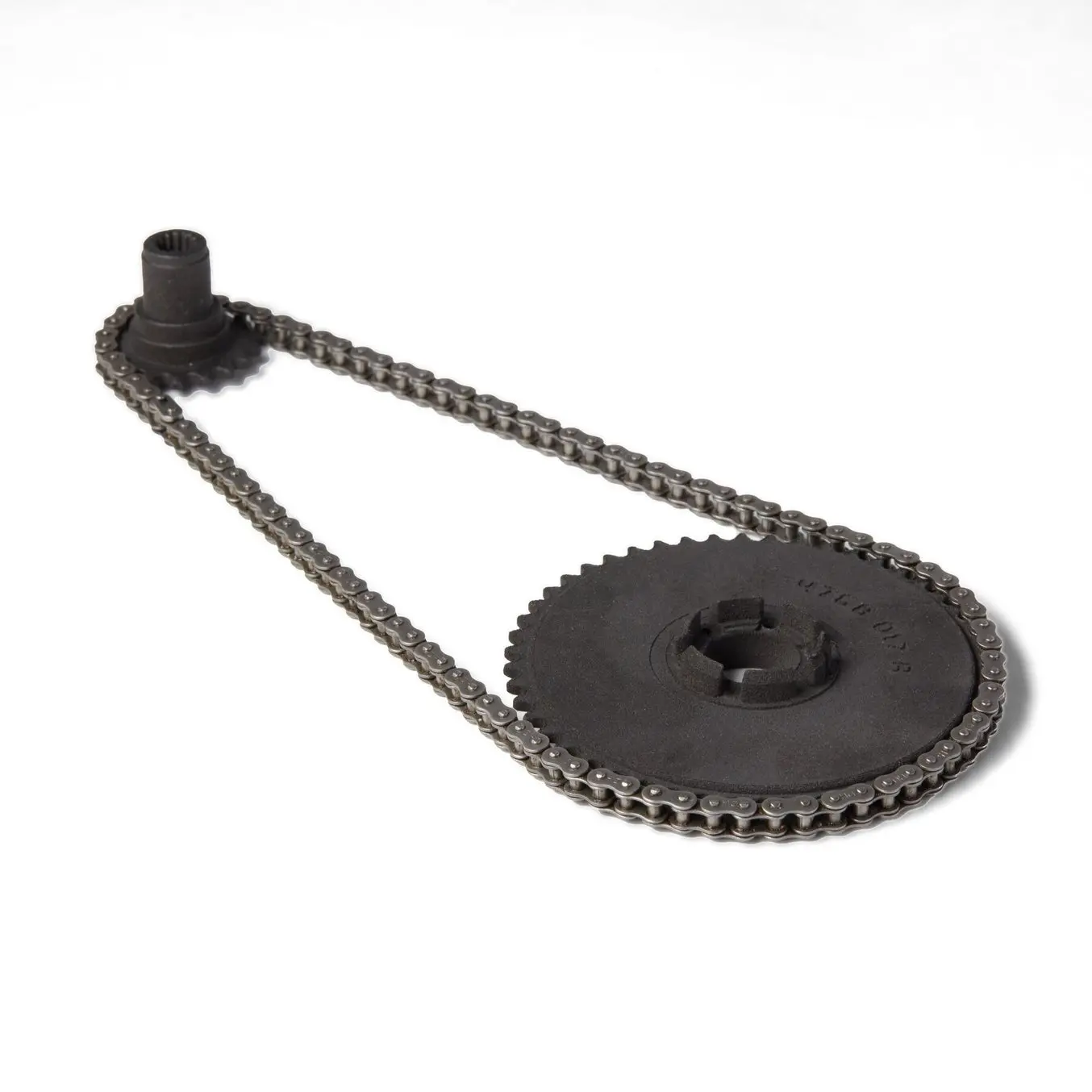
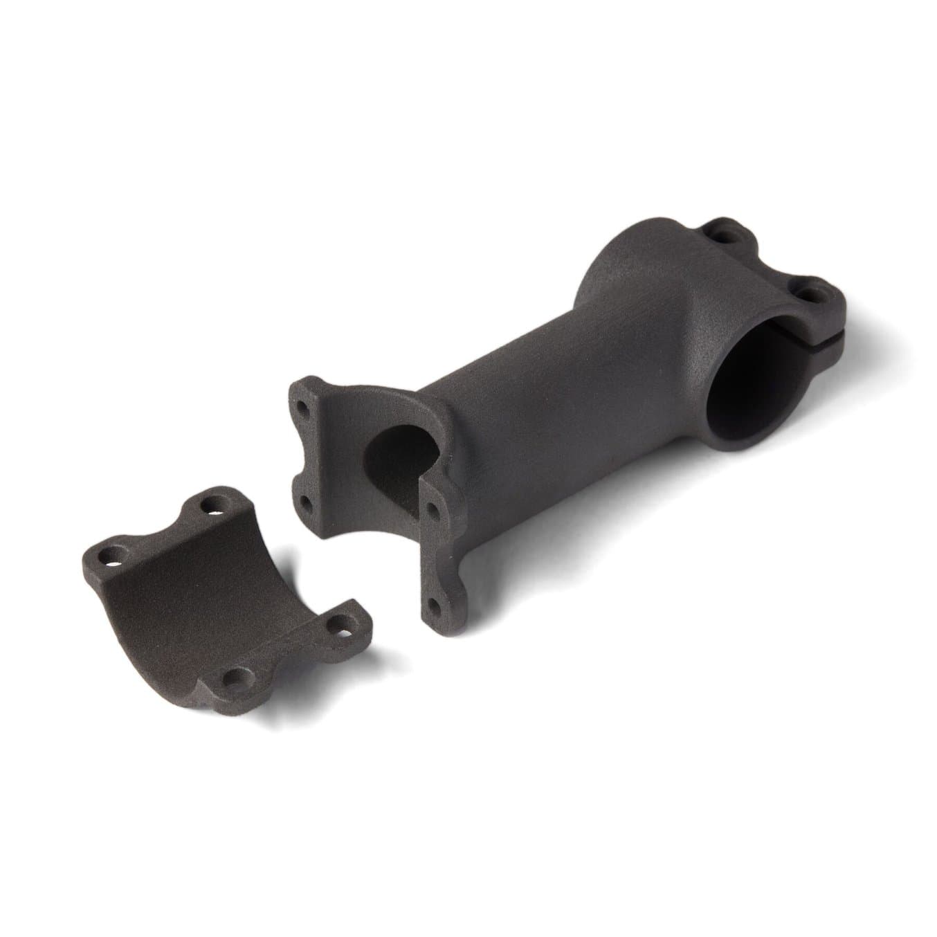
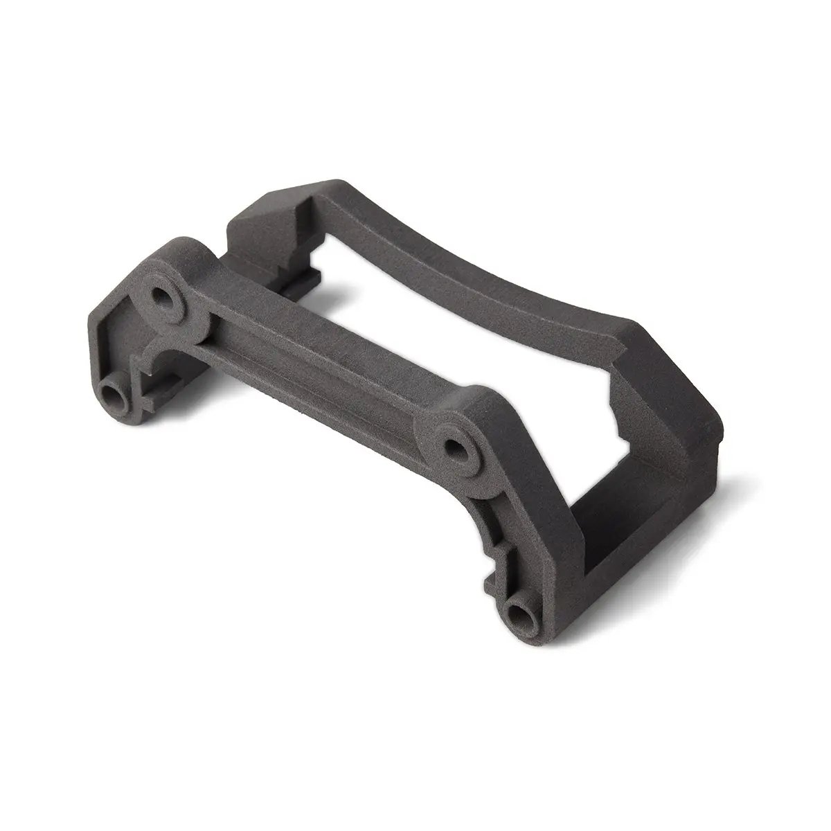
El Nylon 11 CF Powder de Formlabs es tenaz, ligero y resistente al calor, lo que lo hace ideal para aplicaciones automovilísticas, aeroespaciales y de fabricación.
Solicita una pieza de muestra gratuita
Experimenta la calidad de Formlabs de primera mano. Enviaremos una pieza de muestra gratuita a tu lugar de trabajo.
Empieza a trabajar con la fabricación de fibra de carbono
La fabricación de polímero reforzado con fibras es un proceso de trabajo intensivo, complejo, pero aun así emocionante. El uso de moldes y patrones impresos en 3D para fabricar piezas de fibra de carbono permite a las empresas reducir la complejidad del flujo de trabajo, aumentar la flexibilidad y las oportunidades de diseño y reducir los costes y los plazos de entrega.
Materiales como el Nylon 11 CF Powder para las impresoras 3D SLS de la serie Fuse permiten imprimir directamente piezas impresas en 3D que ofrecen muchas de las ventajas de la fibra de carbono, aportando además flexibilidad en la geometría del diseño y un proceso más simple y eficiente.
Para hablar de tu aplicación de la impresión 3D y averiguar cuál es la mejor forma de utilizarla para piezas de fibra de carbono, ponte en contacto con nuestro equipo.