This post was written by Formlabs applications engineer Amos Dudley. Amos worked with Formlabs designer Aashman Goghari to conceptualize, design, and fabricate the FUSE pavilion.
Scale means different things to different people. For product engineers and entrepreneurs, scale is about the quantity of units in production. For architects and designers, scale is about the size of the design, and how it relates to the people who inhabit or use it.
Selective laser sintering (SLS) technology opens up the possibility of 3D printing at scale in both senses of the word. Designers can densely pack builds to produce many parts at once, and each of those parts can be unique and respond to individual needs, since SLS printing eliminates the need for tooling.
To put SLS technology’s capabilities to the test, we decided to build a large pavilion structure to serve as a unique meeting space during the 2017 FUSE conference. We used the Fuse 1 SLS printer to produce more than a hundred unique construction modules en masse, which were assembled in four days to create a structure covering 150 square feet.
Read on to explore how we addressed the challenges and big questions that come along with the freedom of scaling.
Table of Contents
If you can create any shape, what do you make?
Learn about the design process for the FUSE pavilion.How do you translate an STL into a structure?
Learn how to generate a working structural system from arbitrary shapes.How do you fabricate hundreds of unique parts?
Learn about 3D part packing and the tools that we used to automate fabrication.How do you assemble a huge kit of parts?
Learn about the challenges and future possibilities for assembling parametric architectures with large numbers of components.
If You Can Create Any Shape, What Do You Make?
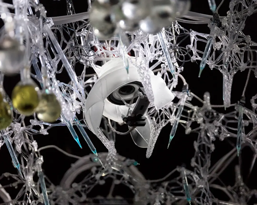
All 3D shapes can be abstracted into meshes made of points, edges, and faces–that’s how an STL file represents a printable object. Usually, we try to design with enough resolution that the mesh disappears when the part is printed at a given size. But what happens if we use the facets of a mesh to our advantage, by automatically translating the STL into a structural system?
Each point where edges intersect turns into a unique connector node, each edge becomes a strut, and each face becomes a panel. This concept gives us the freedom to fabricate nearly any shape at larger-than-human scales.
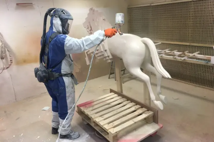
Making large stuff is fun, and we started off thinking about simply scaling up iconic objects. Our first ideas were a scaled up Stanford Bunny and a Formlabs logo. We eventually decided we wanted to create something with a more explicit purpose, so we started designing a pavilion for FUSE 2017.
Structural Pavilion Design
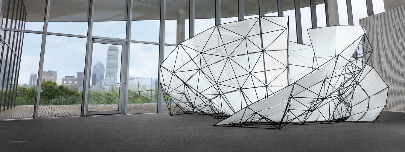
We landed on a design derived from the equation for a mobius strip, revolved to create an enclosed meeting space surrounded by three large, sweeping blades. The blades become rigid and structural by adding a space frame to the rear side.
The pavilion is by far the largest structure that we know of made with Formlabs parts: at 15 ft across and 8.5 ft tall, it was able to fit three people comfortably inside.

Depending on how big you want to build, structural considerations quickly become important for frame construction. Some shapes are self-supporting for a given size and material, others need extra support on the inside or outside to be freestanding and rigid.
We chose materials that would help enable the design, which dramatically thrusts out and over the ground with no wire or columnar support. The connector nodes were printed on the Formlabs Fuse 1 in Nylon 12, a lightweight, rigid, and extremely strong engineering thermoplastic.
What’s Possible with SLS 3D Printing?
Read more about the power of nylon, and when to consider using selective laser sintering over other additive and traditional manufacturing methods.
Learn About SLS

We selected hollow fiberglass tubing, another light, strong material, for the struts. The laser-cut HDPE panels were the heaviest component at almost 100 lbs; before adding the panels, a single person could easily lift the entire structure.
How Do You Translate an STL Into a Structure?

We used Rhino to transform the basic NURBS surface into a space frame, which gives the surface rigidity and structure. By using parametric design to generate the form, we were able to adjust the “resolution” of the structure (how many edges and faces approximate the surface) on the fly. This is important, because resolution is related to cost and difficulty of assembly (more on that later).
Learn modeling strategies and software workflows for producing intricate architectural models in-house.
We used Grasshopper scripting in Rhino to generate the connector models and edge lengths. The module generation system works from a 3D mesh, which could be designed in any CAD software. A script takes into account the angle of nearby edges to set the length of the positive features on the connector, to prevent our round struts from intersecting. It also generates a part number, which is automatically embossed on each connector.

We optimized the underlying shape of the connector nodes for weight and printing efficiency. While a solid round outside connector would be very strong, it would also take up the most space when printing and use the most material. The inside connector node design uses the least material and has the lowest print time.

Achieving the panel shapes was much simpler, using the Unroll function in Rhino on the original surface to get a 2D vector laser cutting diagram. With a folder full of connector models, a list of edge lengths, and a drawing of our panels, we could start fabricating the structure.
How Do You Fabricate Hundreds of Unique Parts?
All 144 of the 3-inch Nylon 12 connectors for our pavilion are printable in a single build on the Fuse 1 in 36 hours. SLS 3D printing technology doesn’t require supports, so the full build volume can be used to print hundreds of unique parts at once. We hope our pavilion connectors represent the future possibilities of mass custom manufacturing, where each part can respond to unique and individual needs.
3D Part Packing
Fitting 144 irregular parts into a build requires a technique more sophisticated than naively stacking them. Fortunately, using 3D part packing algorithms, we can compute optimized arrangements of parts where they nest closely against each other. This strategy has long existed as a way to get the most efficiency out of the million-dollar SLS printers of the past.
We tried several off-the-shelf solutions for part packing, with mixed results. Netfabb uses a Monte Carlo Search to pack, and had the best results of the commercial solutions we found. We were able to fit about 50 nodes into the Fuse 1 with Netfabb. However, Netfabb struggled with the concave geometry of our connector nodes, and the simulation also took the better part of a day.
Ideally the connector nodes would nest close together with overlapping concavity. To achieve this, we built a physics simulation in the Blender engine to pack connectors into a virtual print volume. The connector nodes move and rotate when they intersect, and come to rest when they are free from any overlap.
We used a physics simulation in Blender to optimize packing parts into the Fuse 1 build volume.
The parts wiggle chaotically until none of the parts in the entire set overlap. The entire simulation takes about a minute.
We greatly sped up the packing simulation by using simplified proxy models to calculate collisions, rather than the final high-resolution connector nodes. This method doesn’t guarantee a mathematically optimal solution, but it works well. Most importantly, we were able to fit almost three times the number of connector nodes into a single build volume.
Even at the fabrication stage, we used the strengths of parametric design to find a resolution of parts that would fit our timeline and project scope. The best resolution gave a good impression of the 3D curved shape, fit all the parts into the build, and could be completed in a week-long fabrication schedule. By speeding up part packing and increasing efficiency, we had much more flexibility to iterate on the shape of the final structure.

After the 2017 FUSE Conference, Michael Fogleman (hacker extraordinaire), who now works at Formlabs, released an open-source solution for 3D part packing. Automatic part packing will be included in PreForm for the Fuse 1.
Printing Large Volumes in SLA
We could have used an off-the-shelf part for the panel hanging hardware, but we had a short schedule and geometric needs specific to our design. We decided to fabricate our hangers using stereolithography (SLA) 3D printing in Durable Resin.

We used the Form 2 to rapidly create 505 custom hangers in several days. We designed the parts to stack in 3D in CAD, and let PreForm handle support generation, allowing us to print 98 hangers in a single print. Removing the part from supports was as simple as tearing off a piece of perforated paper.
Form Cell, Formlabs’ new solution for automating part production with stereolithography, was in development throughout fabrication of the pavilion, but would have expedited the hanger printing process. Learn more about automated 3D print production.
How Do You Assemble a Huge Kit of Parts?
Assembling the space frame at Formlabs HQ.The hardest part of creating a large modular structure is the assembly.
Three people spent six hours a day for four days constructing the pavilion. We took the guesswork out of building the frame by projecting a 3D diagram of the structure on the wall and pre-sorting all of the parts. Even so, the build was a test of spatial reasoning and patience; simply finding and orienting each part in physical space took considerable time.
With a small budget and a structure of manageable size, we chose to tackle construction through manual labor, but what if someone wanted to build even bigger, or make structures with higher resolution and detail? Robotics might have the answer–machines are much better than humans at moving parts to precise locations, and architects are already starting to build structures with robotic fabrication.
The Future of Digital Manufacturing and Architecture
As designers, we imagine a future where converting a digital-spatial concept to a physical reality is seamless and automatic, like 3D printing. The construction system used to build the FUSE pavilion can also be applied to interior design, furniture, sculpture, and more. When we combine tomorrow’s construction methods with digital fabrication tools like the Fuse 1, there will be nothing standing in the way of architects and any form imaginable.

Watch Talks From The Digital Factory
Hear from the front lines of the future of fabrication in talks from The Digital Factory, a conference that explored innovation in manufacturing, engineering, design, and creation.
Watch the Talks