
Reverse engineering is a powerful way to create digital designs from a physical part, and can be a valuable tool in your prototyping toolkit alongside technologies like 3D scanning and 3D printing.
3D scanners measure complex objects very quickly, and can speed up your design workflow tremendously when real-life references are involved. With the ability to capture and modify physical shapes, you can design 3D printed parts that fit perfectly on existing products of all kinds. 3D printed jigs allow you to repeatedly locate a drill or saw, or assemble parts precisely with adhesive. Create close-fitting, reusable masks for sandblasting, painting, or etching.
In this guide, we’ll walk through the step-by-step reverse engineering process for an aftermarket digital gauge and explain how to scan a part for 3D printing, with tips along the way for using the right reverse engineering tools, from CAD software to resin 3D printers.
Looking for a 3D scanner for your professional 3D printer? Read our detailed guide on choosing the best 3D scanner to use with your 3D printer.
Book a Free Consultation
Get in touch with our 3D printing experts for a 1:1 consultation to find the right solution for your business, receive ROI analyses, test prints, and more.
From Physical to Digital: Meshes and Solids
One of the biggest challenges people encounter when converting physical objects to digital is a major incompatibility between two different types of 3D models: meshes and solids.
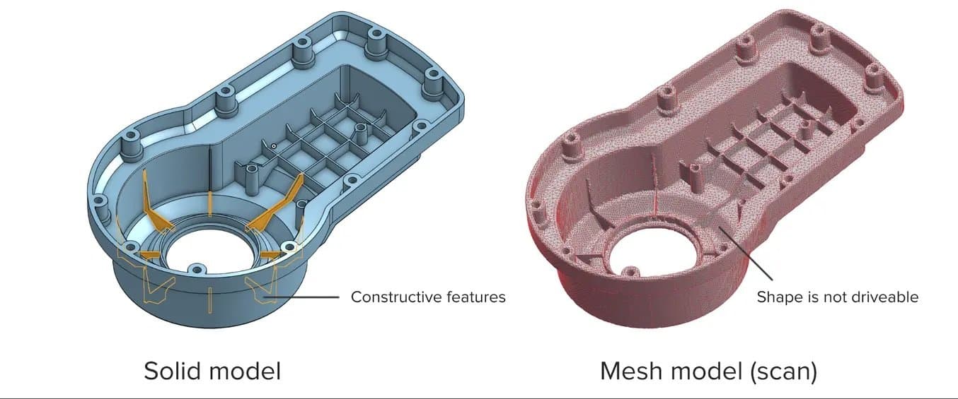
A 3D scanner outputs a mesh, rather than a constructive “solid” model. Meshes need to be reverse engineered to be made editable.
Meshes are the main output of all 3D scanners, and the format commonly understood by 3D printers (STLs). A mesh represents the surface of a shape with a large number of triangles, connected edge to edge. Mesh models don’t contain any information about the object, besides the position of the triangles that define the shape.
On the other hand, engineers are trained to work with solid models. Solid models hold information about how an object is designed, and this information is explicitly encoded into the model as features in a ‘stack’ of logical steps. In solid CAD, it’s possible to change the dimensions for a single feature, and the rest of the model will update to accommodate the change.
Since meshes lack information about the construction of the object, the ways you can alter a mesh model are limited — CAD software like Solidworks and Onshape can’t directly modify meshes. If you need to make major modifications to the underlying design of a scanned part, the mesh needs to be converted to a solid CAD drawing: this process is reverse engineering.
How 3D Scanning Supports the Modern Product Development Process
Watch this webinar with Peel 3D to explore how to integrate 3D scanners into your 3D printing workflow to elevate your product development process.
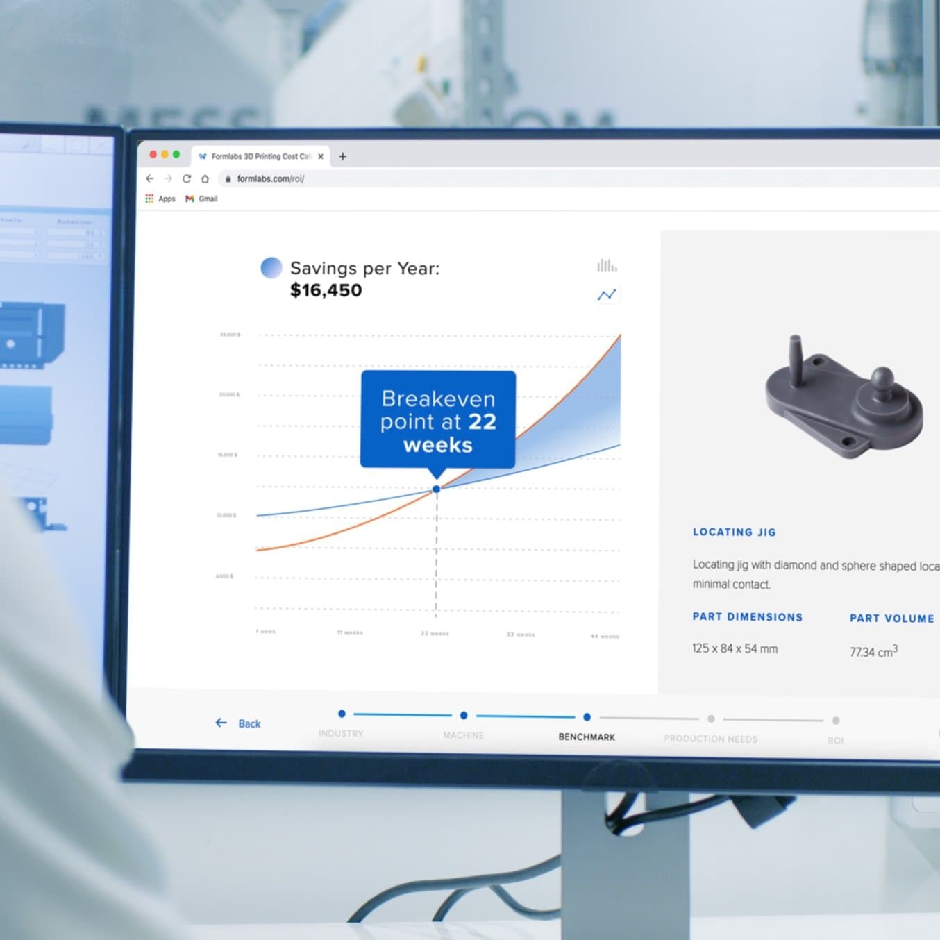
Calculate Your Time and Cost Savings
Try our interactive ROI tool to see how much time and cost you can save when 3D printing on Formlabs 3D printers.
How To Scan an Object for 3D Printing: The Reverse Engineering Workflow
Reverse engineering is important when you want to create new parts that reference or incorporate older designs, where the original CAD design isn’t accessible.
For example, you can create replacement parts that match the original design of damaged existing pieces, or use reverse engineering processes to integrate complex surfaces from existing objects into 3D printable jigs, which are useful when modifying mass manufactured and handcrafted products.
Reverse engineering is often used as the basis for new designs to be assembled with existing components. Without modelling every relational object, it can be difficult to catch all potential issues that might arise from assembly entirely in CAD. Attempting to reverse engineer parts in CAD first can result in a costly trial and error process. 3D printing allows you to quickly test and iterate on reverse-engineered designs in physical space, where it’s much easier to recognize any issues.
In addition to large-scale design changes, it’s important to be aware of possible fit issues arising from measurement error. If the target object has undercuts, very thin bosses (raises above a surface), or deep pockets that are challenging to scan, you might need to use guesswork to fill in missing regions in CAD. Physically assembling a printed prototype can be a quick way to find and resolve potential spatial conflicts in your design, whether caused by new modifications or measurement errors from scanning.
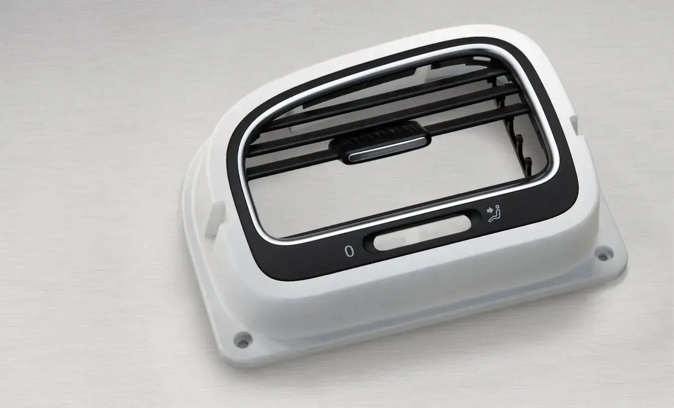
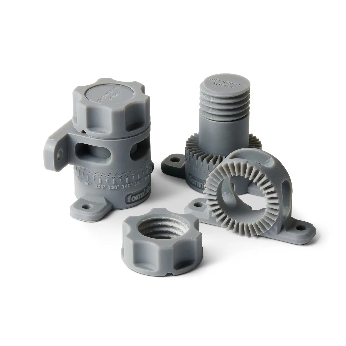
To demonstrate the basic steps in a reverse engineering workflow, let's take a look at the process for creating an assembly jig for an aftermarket digital gauge that fits onto the air vent of a Volkswagen Golf.
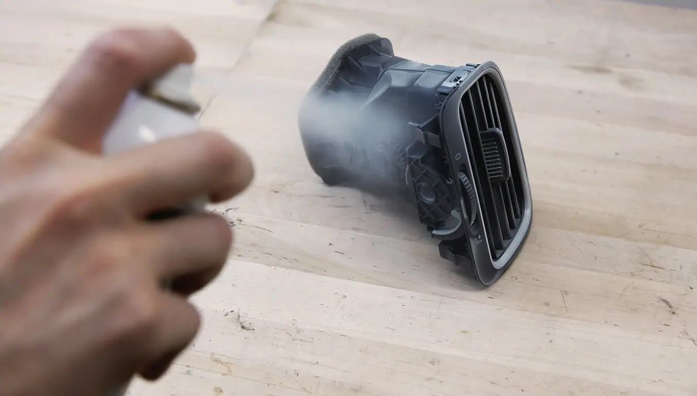
1. Prepare the Object for Scanning
Spray coat the object with a temporary matte powder to improve scan accuracy. Even slightly glossy surfaces tend to degrade scan quality, while reflective and transparent surfaces cannot be scanned at all without a matte coating.
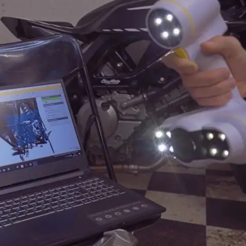
2. 3D Scan the Object
Use a high accuracy 3D scanner to capture the important sections of the part. Tabletop structure light or laser scanners are the right tools for the job, with accuracy of ±100 or better.
Note: You may need to orient and re-scan your object several times if the object has deep recesses.

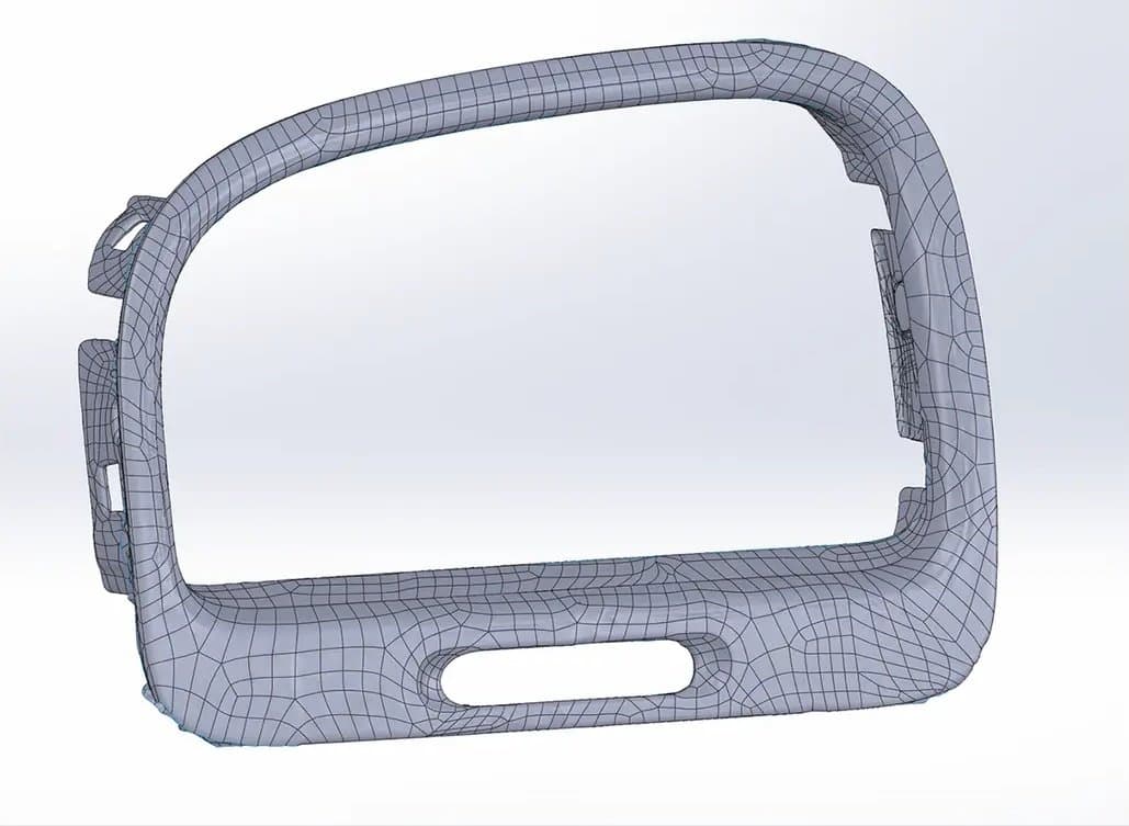
3. Refine the Mesh
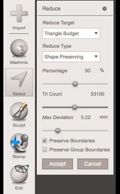
Some scanners produce extremely large mesh files, which will make later steps grind to a halt. Scanner software repairs small gaps and simplifies the scan, making the data more manageable in CAD. Try to reduce the model as much as possible without destroying important details.
Tip: If you need more control, Meshmixer is a great choice for refining scanned meshes.
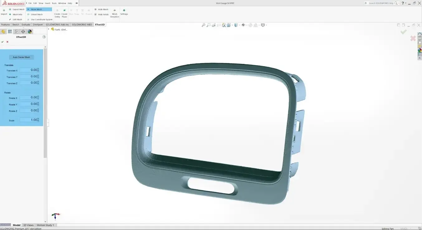
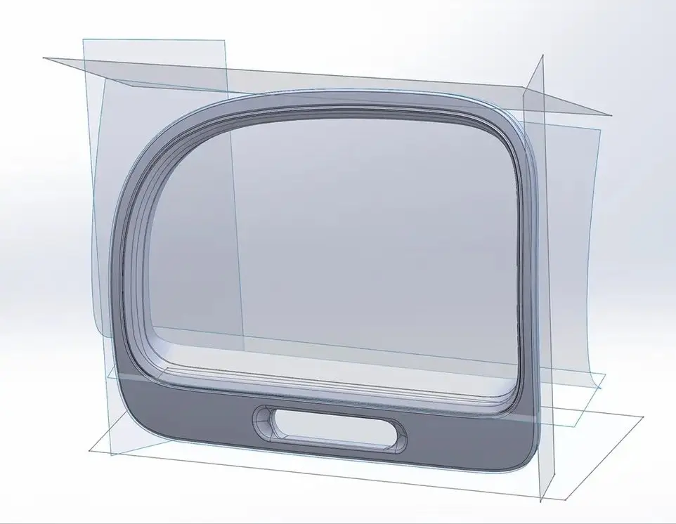
4. Import the Mesh to CAD
Import the mesh into CAD software equipped with reverse engineering tools. Geomagic for Solidworks is a powerful choice for resurfacing complex, organic shapes. If you are reverse engineering a part with simpler flat surfaces, Xtract3D is a less expensive, lightweight alternative. In this step, move and rotate the scan mesh into alignment with any existing design components.
Tip: Make drawing easier by rotating and aligning your scan to face the orthographic view directions.
5. Extract Important Surfaces
There are three paths to extract the shape of the scan in order to create a solid model that is editable with CAD tools: semi-automatic surfacing, automatic surfacing, and manual redrawing.
Semi-Automatic Surfacing
Complex curved surfaces are difficult to manually draw, so you may choose to use semi-automatic surfacing. This function generates surfaces that fit to detected regions of the scan. By varying the sensitivity of the surface detection function, different surfaces will be found.
Tip: Geomagic for Solidworks detects surfaces on the scan to fit 3D curves. Use a “brush” to manually add or subtract areas on the scan from each region.
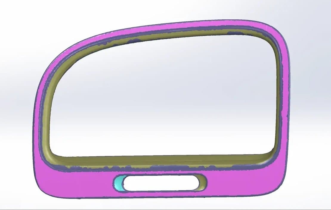
You may need to repeat this process several times with different sensitivity settings to detect all your surfaces. These surfaces can then be trimmed and knit together to create an editable solid.
Use semi-automatic surfacing to re-create curved shapes when you want maximum editability later on, and when sharp edge accuracy is important.
The re-surfaced result, after trimming.
Automatic Surfacing
Automatic surfacing generates a solid model from any watertight scan. You can use standard CAD tools to subtract and add to this auto-surfaced body, but it will be more difficult to move basic features around on the body itself.
You may not need control over edge placement. For example, if you are scanning a part of the human body to create custom ergonomically-shaped products, or want to create a jig to precisely or repeatably modify a handmade object. In these cases, automatic surfacing is a great way to save modeling time.
Note: Compare the results of an automatic surfacing to semi-automatic surfacing: some accuracy is lost, especially around sharp edges.
Manual Redrawing
For simple features such as bosses, holes, and pockets, it’s usually fastest and most accurate to redraw the features using the scan model as a reference. Reverse engineering software allows you to create sketch planes aligned with flat surfaces on the scan and to extract cross sections from the scan mesh, which helps you match the shape of the original object.
6. Integrate New Objects
Once the scan has been converted to a solid, it can be subtracted from another solid body to create a jig that securely holds the original part.
The design of the new gauge component also references the dimensions of the scan, using curves extracted with semi-automatic surfacing.
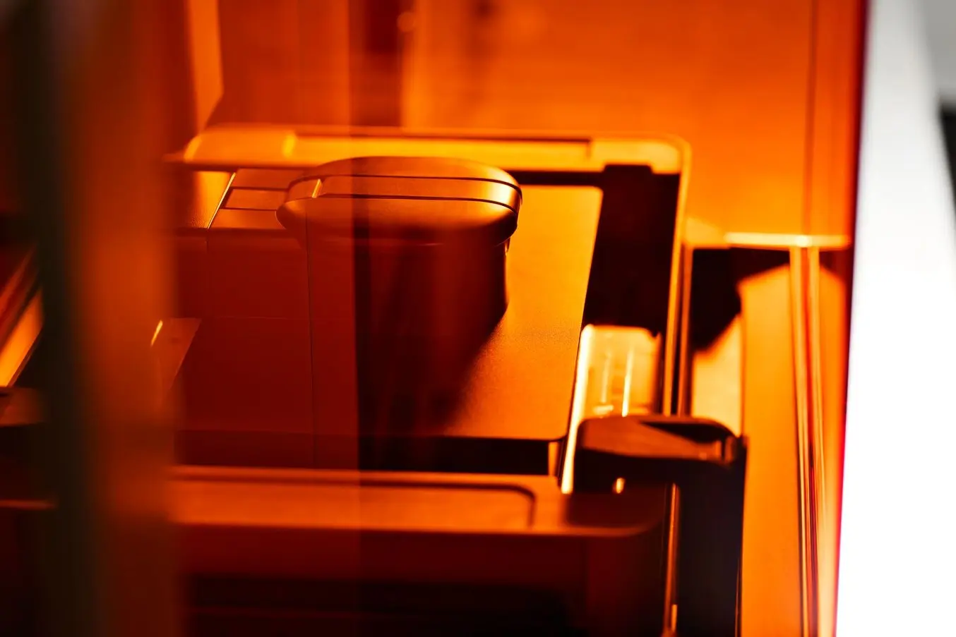
7. 3D Print the New Design
The final 3D printed assembly jig, printed in Rigid 4000 Resin.
Printing the jig on a Formlabs stereolithography (SLA) 3D printer gives you a high degree of accuracy comparable to the output of engineering-grade 3D scanners. Formlabs offers a wide range of engineering 3D printing resins for various applications.
Once these steps are complete, the 3D printed jig is ready to use to assemble the new gauge onto the OEM air vent.
Request a Free Sample Part
See and feel Formlabs quality firsthand. We’ll ship a free 3D printed sample part to your office.
Applications That Combine Reverse Engineering and 3D Printing
Reverse engineering is often used as the basis for new designs to be assembled with existing components. Without modelling every relational object, it can be difficult to catch all potential issues that might arise from assembly entirely in CAD. Attempting to reverse engineer parts in CAD first can result in a costly trial and error process. 3D printing allows you to quickly test and iterate on reverse-engineered designs in physical space, where it’s much easier to recognize any issues.
In addition to large-scale design changes, it’s important to be aware of possible fit issues arising from measurement error. If the target object has undercuts, very thin bosses (raises above a surface), or deep pockets that are challenging to scan, you might need to use guesswork to fill in missing regions in CAD. Physically assembling a printed prototype can be a quick way to find and resolve potential spatial conflicts in your design, whether caused by new modifications or measurement errors from scanning.
Engineering and Manufacturing
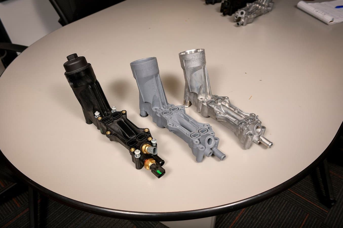
This engine component had been failing for many car owners, iterations from Dorman's redesign showed here.
3D Printing Helps Dorman Keep Pace with Automotive OEMs
Dorman Products is a manufacturer of aftermarket automotive parts. The products Dorman carries range from key fobs and basic engine components, to complex electronic modules and heavy-duty truck parts. Dorman analyzes OEM part failures, and reverse engineers the product, in some instances completely rethinking and improving the design.

Different versions of the intake manifolds printed with the Form 3.
Making Heat-Resistant End-Use Parts and Spares for Motorsport
Andrea Pirazzini, the founder of Help3D, used Formlabs 3D printers to reverse engineer an intake manifold for a pit bike that he rides at the 12 Pollici Italian Cup championship. The scan of the four-stroke engine (two-valve) engine with its frame and carburetor helped him to correctly size the manifold and then to position it so that the carburetor would not crash into the frame or the exhaust system.
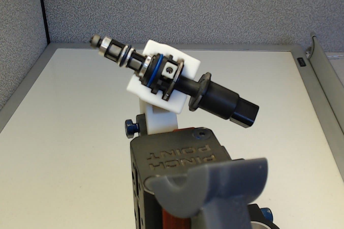
The pneumatic cylinder assembly; complete with 3D printed grippers holding the fuel injector.
3D Printing Custom Fuel Injector Grippers for a Pick and Place Robot
STS Technical Group works with clients on technical design and engineering challenges. To design a fuel injector gripper for a pick and place robot they used a Creaform laser 3D scanner and VX Elements modeling software to get a virtual 3D scan of the fuel injector to assist with the design of the grippers. The scan resulted in an image with intricate details, instead of having to tediously measure every gap, cylinder, and opening on the fuel injector.
Custom Ergonomics
When a product needs to be held or touched by the human body for long periods of time, the importance of ergonomic fit increases. A fit that’s acceptable for a few minutes of use can become uncomfortable after many hours, and improper ergonomics may even lead to repetitive strain injuries.
When it comes to ergonomics and customized products, 3D printers and scanners are complementary tools. 3D printers can produce individualized components and products to order, like orthotics, hand-held grips, and eyewear, without expensive manual labor.
Reverse engineering organic shapes is surprisingly simpler than reverse engineering mechanical parts with tight tolerances, given the right tools. The “Auto Surface” function of Geomagic for Solidworks will generate a smooth CAD surface from a scan (STL) with organic surfaces. Automatic surfacing will eliminate noisy or rough surfaces — a helpful feature when converting an impression into a product.
Once you have a surface that you can edit with solid CAD tools, you can easily subtract or add features that allow the part to interface with other generic components, like bolt hole patterns, mounting plates, and other fittings.
Advanced Prosthetics Made Accessible at PSYONIC
PSYONIC's Ability Hand is an upper-limb prosthesis that used 3D printing for rapid prototyping, mold-making, and end-use parts. Lead Mechanical Engineer James Austin says, “There are, occasionally, parts that we need to be compatible with other companies’ products, and these can sometimes be purchased, although, like many things in the medical industry, they come at an exorbitant cost. For smaller parts, we actually have the capacity to fairly easily reverse engineer the shape and form, and then simply produce them ourselves in house.”
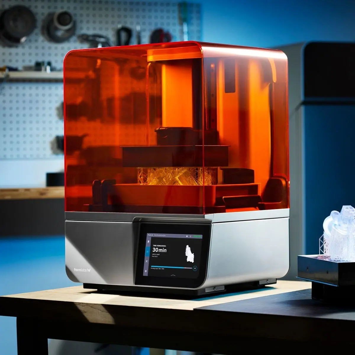
Product Demo: Form 4
See how Form 4 can enable new levels of productivity and innovation through its unmatched speed, accuracy, and reliability.
The Right Tools for Reverse Engineering
The first step to start reverse engineering parts is to find the 3D scanner that is best for your needs. Read about which 3D scanners complement high accuracy 3D printing here.
Learn more about bringing your designs to life with 3D printing; explore stereolithography (SLA) and selective laser sintering (SLS) 3D printing technologies or request a free sample part to evaluate Formlabs materials for yourself.
Not sure which 3D printing solution fits your business best? Book a 1:1 consultation to compare options, evaluate ROI, try out test prints, and more.