
In-House Surgeon-Led Virtual Surgical Planning for Maxillofacial Reconstruction
Introduction
“Maxillofacial reconstruction with a free microvascular fibula flap has become the reference standard for mandibular reconstruction. Virtual surgical planning and the use of 3D printed cutting guides can enhance the accuracy of this challenging procedure. At our institution, the cost associated with the use of third-party–led VSP has been prohibitive. We hypothesized that the creation and use of an in-house VSP technique is feasible and can be performed by the treating surgeon within a reasonable period. Our objective was to create a novel in-house VSP and 3D printing technique that would be straightforward to use and could be used and replicated by any surgeon in any institution.”
Methods and Materials
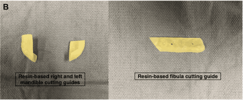
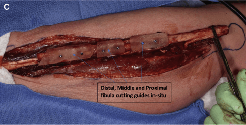
“The cutting guides were printed using a commercially available resin-based stereolithography apparatus desktop 3D printer (Form 2, Dental SG Resin; Formlabs, Somerville, MA). They were sterilized using a steam flush pressure pulse sterilizer. We performed this technique for 19 consecutive patients with maxillofacial benign or malignant tumors requiring microvascular bony reconstruction. Additionally the plates were prebent using an inhouse printed reconstructed jaw model prior to surgery.”
Results
“Of the 19 patients, 17 had undergone reconstruction with a free vascularized fibula flap and two with a free scapula flap…. seven cases were located in the maxilla and 12 in the mandible.”
The technique was found to be simple and repeatable…. The average overall time required for surgeon-led slicing, VSP, and virtual cutting guide fabrication was 158 minutes (two hours, 38 minutes)... As expected, the total time required for planning decreased with increased user experience (156 minutes for the first five cases vs. 79 minutes for the subsequent cases in our series). The average cost for printing the cutting guides per case was $12.80 CAD (incl. amortized costs of the equipment). Whereas our current cost for 1 VSP case planned using a third-party professional company is $2625 CAD. With this technique, the average time required to manufacture the cutting guides was less than 24 hours compared with the two to four weeks it could take for a third-party VSP case to be ready and sent to the surgeon.”
Conclusion
“Using this technique, in-house VSP and 3D printing can be performed by the treating surgeon, without an engineering background, within a reasonable period. Although difficult to study, the introduction of inhouse planning … has allowed for better preparation and less anxiety before each operative case.”
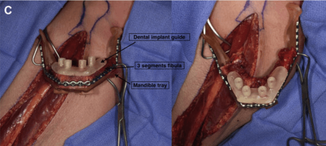
Another technique is used when a full jaw reconstruction is planned. In such cases, the dental implant surgical guide is planned to fit over the fibula bone segments after the segments have been reconstructed together and adapted to a mandible guiding tray.
Formlabs Biocompatible Resins: A Comprehensive Guide To Choosing the Right Material
Formlabs currently offers more than 40 unique materials for stereolithography (SLA) 3D printing. This paper helps users compare and contrast our biocompatible offerings, and determine the best fit for their medical applications.
Accuracy of Guided Surgery and Real-Time Navigation in Temporomandibular Joint Replacement Surgery
Introduction
“Alloplastic replacement (total joint replacement, TJR) has become a standard procedure for the treatment of temporomandibular joint (TMJ) disorders when non-invasive therapy is not feasible or has failed.Sophisticated guided surgery has not been implemented into total joint replacement-surgery (TJR) of the temporomandibular joint (TMJ) so far. Design and in-house manufacturing of a new advanced drilling guide with vector and length control for a typical TJR fossa component are described in this in-vitro study, and its accuracy/utilization was evaluated and compared with those of intraoperative real-time navigation and already available standard drilling guides.”

Preparation of model surgery
(A) A 3D-printed (Clear Resin, Form 2, Formlabs Inc., Somerville, MA, USA) model of a patient’s skull base with right glenoid fossa and parts of the calvaria for fixation of a navigation reference array
(B) The simple (left) and newly designed advanced (right) drilling guides for vector and length control (Clear Resin, Form 2, Formlabs Inc., Somerville, MA, USA).
(C) “Preoperative” virtual surgical plan with stereolithographic model of the advanced drilling guide (green-yellow) and trajectory planning of screw positions and vectors (blue lines with dots on each end).
Methods and Materials
“Skull base segmentations of five CT-datasets from different patients were used to design drilling guides … Stereolithographic models of the skull bases were printed three times for each case. Three groups were formed to compare our newly designed advanced drilling guide with a standard drilling guide and drill-tracking by real-time navigation. The deviation of screw head position, screw length and vector in the lateral skull base have been evaluated. Three-dimensional printing was conducted in the clinic’s own laboratory using a Form 2 printer (Formlabs Inc., Somerville, MA, USA) with Formlabs Clear Resin consisting of acrylic esters.”

Performing model surgery with and without navigation.
(A) Guided surgery with advanced drilling guide (group 1) for vector and length control in a patient model of the right TMJ.
(B) Referencing and setup of navigational instrument/drill-tracking (Brainlab® Kick, Brainlab, Munich, Germany).
(C) Navigation-tracked drilling for vector and length control using a simple drilling guide.
(D) Superimposition of preoperative computed tomography dataset, containing the virtual surgical planning, with the postoperative cone beam computed tomography scan of the surgery model. Drill holes were filled with radiopaque root canal sealer (white arrows).
Red Box: Planned screw vectors (blue lines with dots on each end). The screw head position [mm], drilling length [mm] and vector [degree] (yellow box) were measured (yellow lines) for deviation from the virtual surgical plan (blue vector).
Results
“There was no difference in the screw head position between all three groups. The deviation of vector and length was significantly lower with the use of the advanced drilling guide compared with standard guide and navigation. However, no benefit in terms of accuracy on the lateral skull base by the use of real-time navigation could be observed.”

Boxplots of the measured deviation from virtual surgical planning (median, box height: interquartile range, whiskers: lowest and highest value).
Conclusion
“The presented advanced guide significantly increases surgical precision during screw placement at the lateral skull base with a mean length deviation of 0.66 ± 0.32 mm and a mean vector deviation of 1.9 ± 2.18 degree between VSP and the actually achieved position. This was significantly lower than in control groups. However, navigational drill-tracking was less beneficial than expected. For further improvement of surgical procedures and increased patient safety, this type of advanced guide should be introduced in clinical routine by prosthesis manufacturers.”
A Modified Novel Technique for Condylar Positioning in Mandibular Bilateral Sagittal Split Osteotomy Using Computer-Assisted Designed and Computer-Assisted Manufactured Surgical Guides
Introduction
“Current techniques for orthognathic surgery after Le Fort I osteotomy and bilateral sagittal split osteotomy (BSSO) rely on intermediate and final occlusal splints for proper positioning of the dental arches without any control in positioning the condyle and ramus segments. Setting the 2 condyles in centric relation [CR] in the glenoid fossae at fixation is paramount for condylar function and the accuracy and stability of postoperative occlusion. Usually the two ramus segments are manually positioned and fixated in the final position according to the surgeon's experience. This report describes a novel technique to position the condyle and ramus segments in centric relation using skeletal guides designed by computer-assisted designed and computer-assisted manufactured (CAD-CAM) technology.”
Methods and Materials
“VSP [virtual surgical planning] was performed to correct mandibular asymmetry and digital guides were generated according to the final position of the bone segments and then 3D printed in biocompatible material (Dental SG Resin; Formlabs Inc, Somerville, MA).”
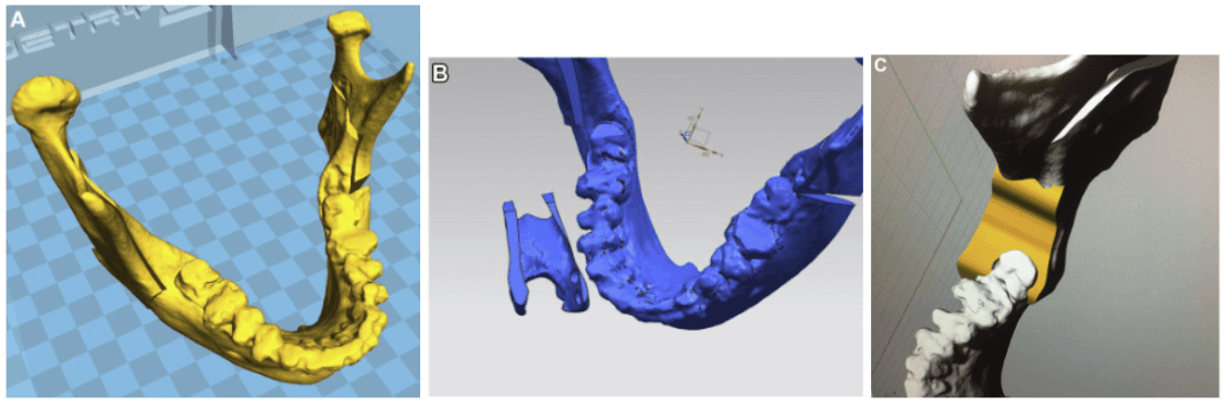
(A) VSP of mandibular bilateral sagittal split osteotomy on a 3D mandibular model
(B) 3D model of the double-U–shaped guide proximally contoured to the anterior border of the ramus and distally contoured to the retromolar trigone and last inferior molar crown. The guide is upside down to show the lower surface of the guide adapting to the bone surface after the osteotomy to fit the bone segments in the new position.
(C) 3D model of the surgical guide adapting to the bilateral sagittal split osteotomy site.
“The skeletal guides have a double-U shape designed to be tooth borne on the distal segment and bone borne on the proximal segment. The guides fit on the last molar crown and the anterior border of the ramus; using these reference points will position the mandibular arch and 2 ramus segments in ideal centric occlusion and centric relation. The condyle position in the sagittal, horizontal, and transverse planes was analyzed by computed tomography and differences in measurements were calculated.”
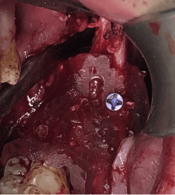
Intraoperative view of the guide positioning the segments and fixated to the proximal segment with single monocortical screw fixation.
Results and Discussion
“The repositioning surgical guides with U-shaped ends for bone (proximal) and dental (distal) anchorage translate the VSP to the operating room with full control of proximal bone segments during fixation, thereby avoiding condylar sag or condylar rotations. The guide is simpler in design and easier to position accurately compared with other guides because its internal surface precisely fits the anatomic region of the osteotomy site. The device allows the operator to position it in contact with the anterior borders of the ramus and with the last mandibular molar to achieve precise mandibular segment positioning with the condyles in CR…
Analyses of the present results … [indicated] that the condyles were well centered in their respective glenoid fossae.”
Conclusion
“This technique confirms that a precise and reproducible outcome can be obtained with centric occlusion and condylar CR using CAD-CAM guides.”
Contemporary management of complex craniofacial trauma: virtual planning, navigation and the novel thermoformed cage splints in a strategic, sequential, computer-guided protocol
Introduction
“It was the aim of the study to assess if computerized simulation and the use of thermoformed cage splints are useful to plan cases of complex craniofacial trauma.”

Thermoformed cage splints fit the template represented by a 3D printed model of realigned dental arches after virtual occlusion setup
Methods and Materials
“This retrospective study enrolled patients presenting at our institution from January 2020 to March 2022. Patients had to satisfy the following conditions: displaced fractures in all the thirds of the maxillofacial skeleton, including the cranio-orbital region, the midface and the mandible [with accompanying occlusion impairment].
Virtual surgical planning with digital reduction of fractures, navigated planning, thermoformed cage splints were used in all cases. Surgical outcomes were evaluated by computing the surface deviation and occlusograms between planned and postoperative models. The virtually reduced dental arches [were] exported as a merged STL file and 3D printed using a Form 2 printer (Formlabs, Somerville, CA, USA).
A thermoplastic sheet was formed over the 3D printed template, resulting in a thin overlay bearing the impression of the reduced dental arches. This process was performed for both the superior and inferior dental arch, yielding a pair of thermoformed cage splints (TCS) to assist bone segment repositioning. In contrast with a traditional splint, containing an almost flat impression of dental cusps, TCS simulate a three-dimensional cage which embraces teeth crowns up to the alveolar bone, acting as a repositioning socket that ensures fitting and constraint of arch segments in the planned position, enabling the three-dimensional restoration of the dental arch.”

After realigning dental arches, thermoformed cage splints are left in place to constrain arches in their reduced position and do not interfere with the use of a dental splint to restore the occlusal relationship.
“In addition, a traditional splint for orthognathic surgery was also printed, allowing to reposition the superior and inferior dental arches in the desired occlusion. It is worth noticing that thermoformed splints are only [a] few hundreds mm thick, therefore they do not preclude the simultaneous use of conventional dental splint to provide final occlusal position.”

Intraoperative application of TCS: A) preoperatively displaced left hemimaxillary segment; B) positioning of the TCS fitting the non-displaced half; C) TCS-assisted reduction of displaced segment and arch reconstruction; D) plating of maxillary bone with TCS constraining displaced segments in the correct position.
Results and Discussion
“13 patients were enrolled in this study… All surgeries were uneventful, and all fracture sites were reduced and fixed in accordance with current AO CMF guidelines.”

Reestablishing the correct relationship for the maxillo-mandibular complex: A) intermaxillary block with TCS in place and an occlusal splint; B) Maxillo-mandibular complex is fixed to upper segments under navigational guidance and then TCS are removed.
“Accuracy of bone repositioning was evaluated compared with the surgical planning. For the mandible, mean Root Mean Square Error (RMSE) was of 1.67 with a standard deviation (SD) of ±0.75 mm (p < 0.001); for the maxilla, average RMSE was of 0.88 with SD of ±0.52 mm (p < 0.001); and for midfacial and upper third bone segments, average RMSE was of 0.59 with SD of ±0.47 mm (p < 0.001).”

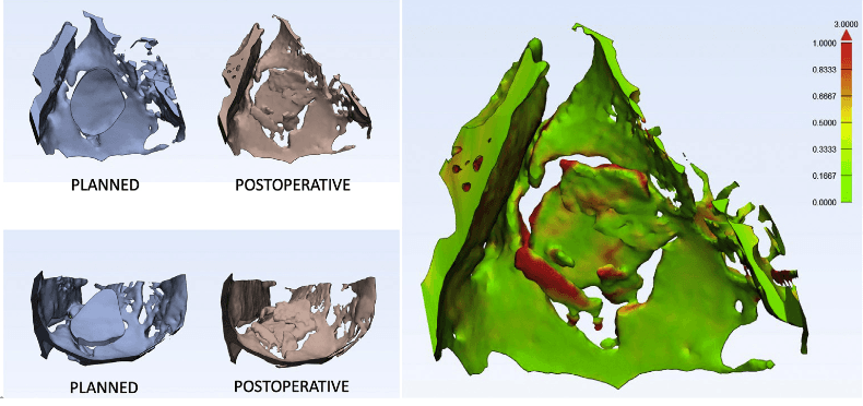
Surface-deviation analysis between virtual surgical planning and postoperative CT scan. A) upper facial segments, including ZMC and NOE; B) maxillary evaluation up to the Le Fort I line; C) mandible evaluation.
“Our results show that the sequential and organized application of technology within an integrated workflow can yield accurate results, as confirmed by superimposition analyses… Overall, results indicate that the average error is far below 2 mm, which is considered clinically acceptable in many studies about orthognathic surgery”
“According to our planning and surgical experience, this workflow is entirely surgeon-based: we support the idea that surgical planning represents an extension of surgical instrumentation and should be performed by surgeons. Compared to outsourcing cases to third-party companies, the most obvious implication is that a point-of-care management is immediately available, and the time spent in the surgical planning by the surgeon is beneficial to improve the conceptualization of the clinical case…”
Conclusion
“Within the limitations of the study [consisting in its retrospective design and a small sample size] it seems that thermoformed cage splints might be a promising alternative to other well-established approaches for accurate occlusal restoration and can be fully integrated within the digital workflow.”
Citation: Alessandro Tel, Fabio Costa, Salvatore Sembronio, Massimo Robiony, Contemporary management of complex craniofacial trauma: virtual planning, navigation and the novel thermoformed cage splints in a strategic, sequential, computer-guided protocol, Journal of Cranio-Maxillofacial Surgery, 2022, ISSN 1010-5182.
Endoscopically assisted computer-guided repair of internal orbital floor fractures: an updated protocol for minimally invasive management
Background
“Performing accurate anatomical reconstruction is a challenging task in the treatment of internal orbital floor fractures [or pure orbital blowout fractures]. Compared with traditional transcutaneous incisions, endoscopic transmaxillary approaches have the advantage of avoiding complications related to external scars, and provide direct access to the orbital floor. Autogenous bone provides the ideal material for defect reconstruction, but determination of the correct size and shape of the graft is crucial for a stable support. This study introduces a new protocol for the treatment of internal orbital floor fractures that combines endoscopy, virtual reality, and 3D printing. The authors also investigated the impact of computer-aided surgery (CAS) on the overall accuracy of reconstruction in aiming to achieve the triple objective of restoring anatomy, volume, and function.”
Methods and Materials
“Fourteen patients with orbital floor fractures were recruited for this study. High-resolution CT scans provided appropriate imaging for detailed orbital floor defect visualization. A virtual reconstruction of the orbital floor defect was developed and a 3D printed template was fabricated to provide intraoperative guidance in the graft harvesting phase, according to the orbital defect. Virtual analyses were conducted to evaluate the accuracy of reconstruction both in terms of graft size and graft orientation.”
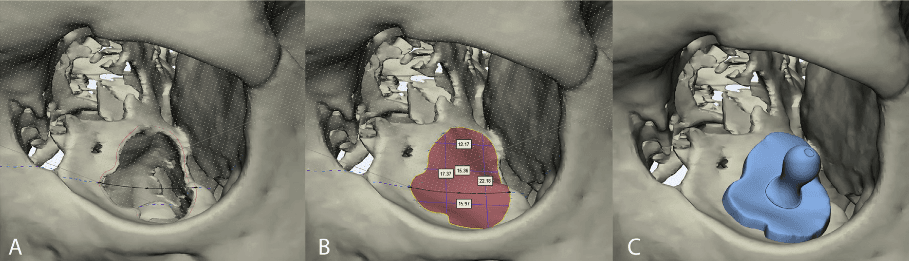
Virtual surgical planning in orbital floor reconstruction. A) A curve is drawn to outline the defect. The curve is slightly larger than the size of the defect to facilitate accommodation of the graft onto the fracture rim. B) Virtual reconstruction of the orbital floor is performed independently of the contralateral orbit. A spline (black curve) is interpolated with the outline curve to recreate the virtual floor. Measurements are performed to verify the size of the graft for intraoperative use. C) The surgical guide is modelled on the virtual reconstruction of the orbital floor.
“The digital reconstruction of the orbital floor was subsequently exported as a reference template to model a surgical guide. The guide was designed to be slightly larger than the orbital defect in order to provide a stable support for the graft. A handle was modelled on the guide to facilitate its positioning using surgical instruments. The surgical guide was exported as an STL (standard tessellation language) file and 3D printed using a Form 2 (Formlabs, Somerville, MA, USA) stereolithographic 3D printer.”
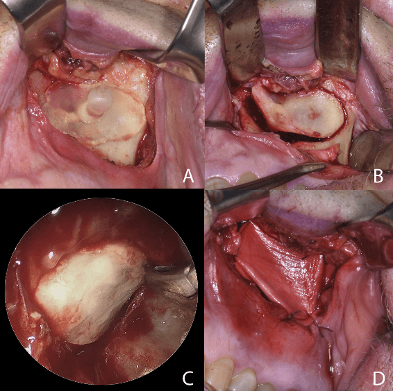
The surgical guide is positioned over the anterior wall of the maxillary sinus to sculpt the window for the endosinusal space. B) The bone fragment is removed and used to reconstruct the orbital floor for class II or class III defects, depending on the size of the maxilla. C) Endoscopic view, showing the correct positioning of the graft and reconstruction of the orbital floor. D) Bone-anchored sutures are used to stabilize biocollagen membrane over the maxillary defect.
Results
“Postoperative CT scans showed that in all cases orbital floor reconstruction was successfully performed, resulting in restoration of the correct globe position. No intraoperative complications occurred. Correspondence of graft size was evaluated using color-coded maps and RMSE, while comparison of angular measurements allowed the authors to relate simulated and actual reconstruction.”
Comparison of planned and achieved orbital floor reconstruction, and color-coded distance map used to quantify size difference between virtual and real grafts.
Conclusion
“Our experience in orbital reconstruction shows that the use of CAD-CAM by surgeons performed within a 3D printing lab can shorten presurgical planning, facilitate intraoperative maneuvers, and increase accuracy of reconstruction.”
“Orbital floor reconstruction performed via transmaxillary endoscopy is a safe technique, which allows for detailed visualization of the fracture rim, avoids external scars, and permits an easier reduction of the prolapsed orbital content into the overlying orbital cavity. Virtual planning plays an important role in defining the appropriate geometry of the bone graft and establishing the optimal reconstruction strategy. Our preliminary results indicate that virtual planning and 3D printing should become part of an integrated protocol for the endoscopic treatment of orbital floor fractures.”
Empowering Innovation in Healthcare
To discover more about the Formlabs medical printers and materials, or to see further peer-reviewed research, visit our medical page or contact our medical sales team.
To read further research related to cranio-maxillo-facial surgery featuring Formlabs technology, read our literature roundup with the industry-leading Mayo Clinic.