
Interlocking parts and assemblies are everywhere we look, and as 3D printing has become a fabrication method for more industries and applications, learning how to 3D print interlocking joints is essential.
Interlocking joints rely on the friction force between two components and involve a protrusion and a corresponding negative space for that protrusion to fit into. From there, the joint will hold firm based on the friction and shape of those two joints, and will prevent disassembly specifically in one direction while allowing it when force is applied from other directions. Interlocking joints are very common in applications with very rigid materials, such as wood, though 3D printed interlocking joints are also common.
Contrastingly, snap-fit joints are designed to deform one feature slightly as the other component pushes past its overhang, then ‘snap’ back into its original position, effectively locking in the mating component. Because plastics can deform repeatedly (better than a material like wood), 3D printed plastic snap-fit joints are a very common method of fabricating assemblies.
Book a Free Consultation
Get in touch with our 3D printing experts for a 1:1 consultation to find the right solution for your business, receive ROI analyses, test prints, and more.
Introduction to Interlocking 3D Printed Parts
There are many examples of interlocking joints and assemblies, from the oldest post-and-beam or log cabin wooden construction methods to chain mail to engine assemblies with components that rotate and move in relation to each other. These types of joints provide numerous advantages. Creating an interlocking joint allows you to:
- Easily assemble and disassemble a structure
- Create systems that are larger than the individual components available
- Join together two or more materials or colors
- Streamline a design or assembly, by reducing the need to manually join parts together through screws, adhesives, etc., while increasing strength
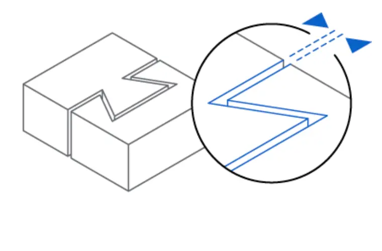
3D printing interlocking joints allows you to print these assemblies in place, unlike traditional fabrication methods for interlocking parts, which need to be created separately and then joined together. In traditional examples like a timber frame house, two large timbers are chamfered (cut at an angle as a transition between two faces) so that their faces are touching, then further held together by pins or pegs. Traditional wooden construction methods create these interlocking parts with what’s known as a scarf joint, or more specifically, an under-squinted, stop-splayed scarf joint.
In traditional chain mail production, open individual links are secured to the previous ring in the sequence and then painstakingly welded shut. Though there is not much need for traditional armor in today’s day and age, 3D printing chain links and larger pieces of mail for prototyping or fashion is an easier and faster way to fabricate.
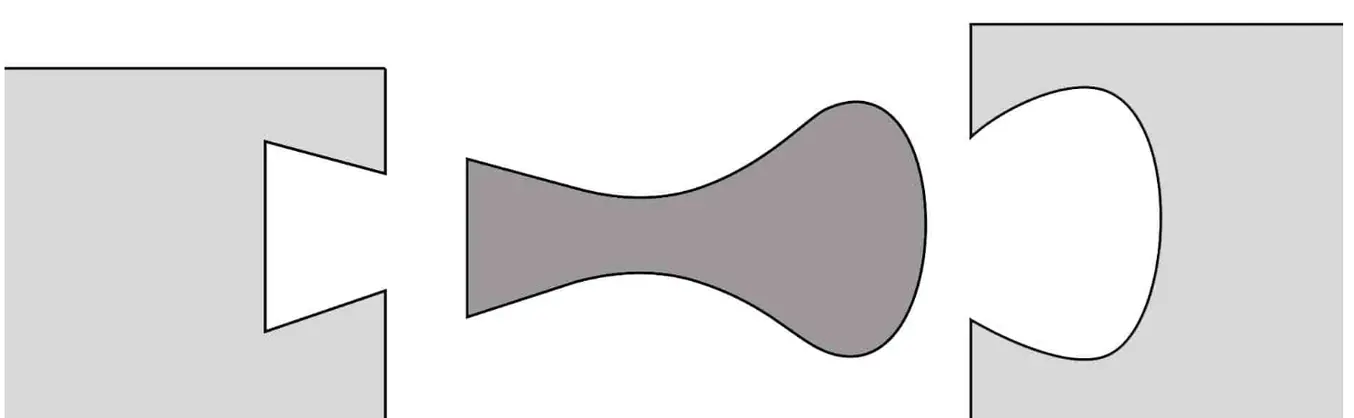
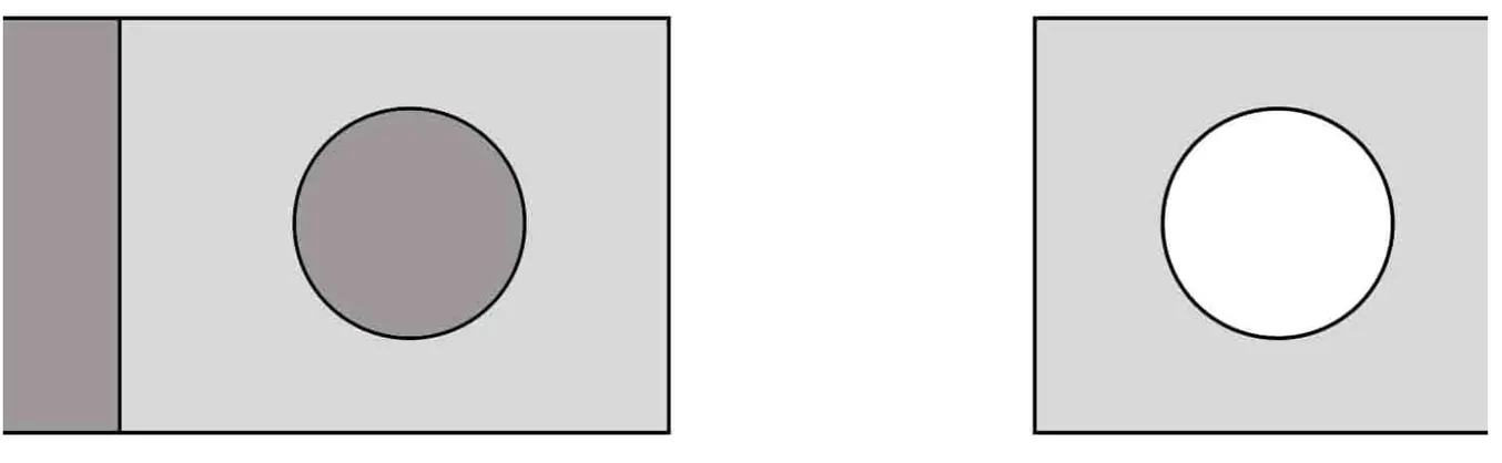
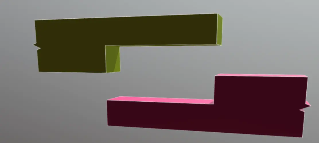
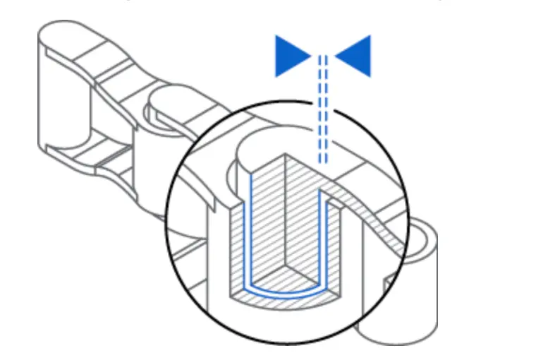
3D printing interlocking joints offers many advantages for designing large products or complex assemblies. One main advantage is that there are some interlocking part features that cannot be manufactured any other way. For instance, in some interlocking part designs, the recesses that a protrusion, tab, or fin grabs onto cannot be machined or molded. In the example below, the interlocking part can only be 3D printed.
3D printing interlocking parts with joints that fit together is easy once you understand a few basic design principles and how to choose the right 3D printer and material for your specific project.
Common Types of Interlocking Joints

Puzzle Piece, Jigsaw, or Tongue Joints
Within types of tongue joints there are ‘T’ joints, ‘I’ joints, or ‘Finned’ or ‘Tabbed’ ‘I’ Tongue joints.
Ideal for 3D printing hobbyist applications and ‘puzzle’ aesthetic joints or consumer product prototyping.

Dovetail Joints
Most popular simple joint to create and extrude in CAD software. Ideal for SLA 3D printed parts with sharp edges and smooth surfaces.
Key Joint
Not ideal for 3D printing — the more parts, the greater the chance of having a variance in tolerances across facades.

Fingertip or Comb Joint
Thin comb edges prone to breakage, not ideal for 3D printing application.
Tenon Joints
On certain low-budget printers such as FDM models, a stepping or layer lines effect could make perfectly round tenon joints difficult. Some post-processing is necessary for each type of technology.
Scarf Joint
Good for 3D printing, larger, chunkier parts will need a higher 0.4 mm tolerance.
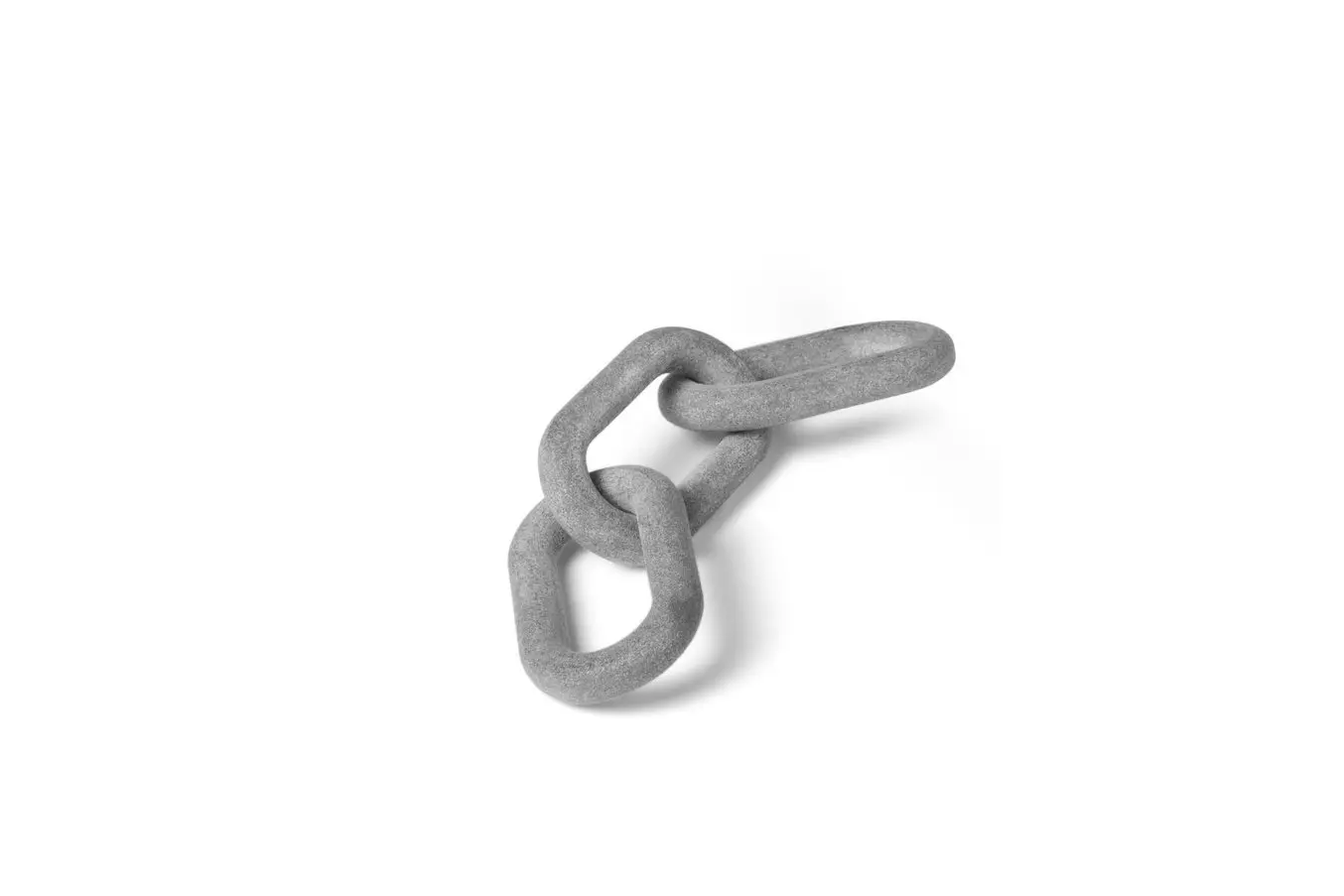
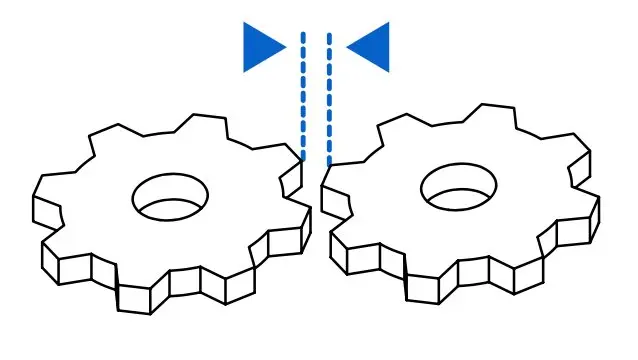
Chain Links
Ideal and most cost-effective through 3D printing. Chain links can be printed in place with either support structures or surrounding powder holding each link separate from its neighbor during the print process to avoid being fused, cured, or sintered into one object.
Choosing the Right Technology for 3D Printing Interlocking Parts
Fused deposition modeling (FDM), stereolithography (SLA), and selective laser sintering (SLS) 3D printers can all be used to create interlocking parts, though there are advantages to choosing one over the others.
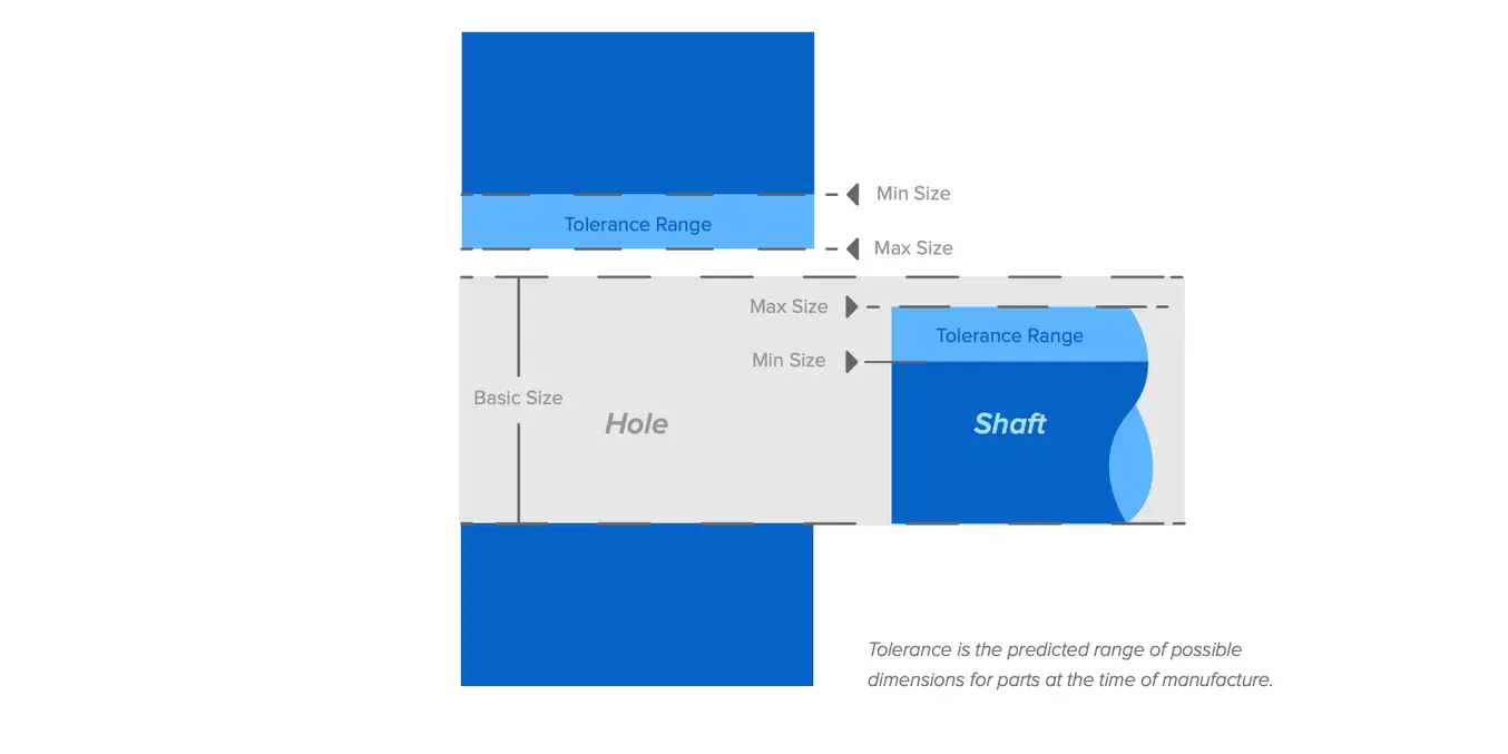
A major factor in 3D printing interlocking parts is tolerancing — the allowed variations in a given dimension. For injection molded interlocking parts, the tolerances are typically 0.1 mm. In 3D printing, however, there are more factors at play. The heat used to extrude, cure, or sinter the plastic may cause shrinkage of the interlocking joint, or a binding agent may add volume, causing larger-than-intended dimensions. However, because some 3D printers can print-in-place, they still provide significant advantages to injection molding two parts that are then joined together through an interlocking feature.
Technologies’ Suitability for 3D Printed Interlocking Parts
| Necessary Tolerances | Advantages for 3D Printing Interlocking Parts | Disadvantages for 3D Printing Interlocking Parts | |
|---|---|---|---|
| FDM | 0.5 mm | Inexpensive for quick form-check prototypes | Anisotropic, layer lines, parts subject to breakage under shear forces |
| SLA | 0.2 mm | Isotropic parts, wide material variability | Less functional strength than SLS |
| SLS | 0.2 mm | Self-supporting parts, functional strength, tight tolerances, mostly isotropic parts | Rougher surface area can add extra friction within the joint |
SLS and SLA technologies are the best for 3D printing interlocking parts. Their tight tolerances and the range of mechanical properties allow the creation of strong 3D printed assemblies with interlocking joints that fit snugly and firmly together.
SLA
SLS
Minimum Assembly Tolerance
Recommended: 0.4 mm/400 microns
Features less than 20 mm2: 0.2 mm
Features greater than 20 mm2: 0.4 mm
Integrated Assembly Clearance
Not recommended because liquid resin in between parts can be difficult to clean without proper drainage.
Features less than 20 mm2: 0.3 mm
Features greater than 20 mm2: 0.6 mm
Considerations for Designing Interlocking 3D Printed Joints
Clearances
The most important thing to keep in mind when designing interlocking 3D printed joints is maintaining precise clearances. The clearance of a joint is the amount of space between the two components in that joint. A properly designed 3D printed interlocking joint will have adequate clearance, such that it can assemble easily without too much force, while also not being too loose and rendered useless.
Tolerances
The clearance between the two components has to allow for the tolerances of the printer and material. Thus, the clearance for an FDM 3D printed interlocking joint has to be larger than that of an SLA or SLS 3D printed joint, because the FDM printer has more dimensional variability.
How to Design Snap-Fits, Interlocking Features, and More for SLS
Tolerance and fit are essential concepts that engineers use to optimize the functionality of mechanical assemblies and the cost of production. Use this white paper as a resource when designing functional 3D printed assemblies, or as a starting point when designing the fit between parts printed.
Material Choice
Another consideration for 3D printing interlocking parts is the material you’ll be designing for — how much rigidity it has, the coefficient of friction, and whether you’ll post-process it to be smoother.
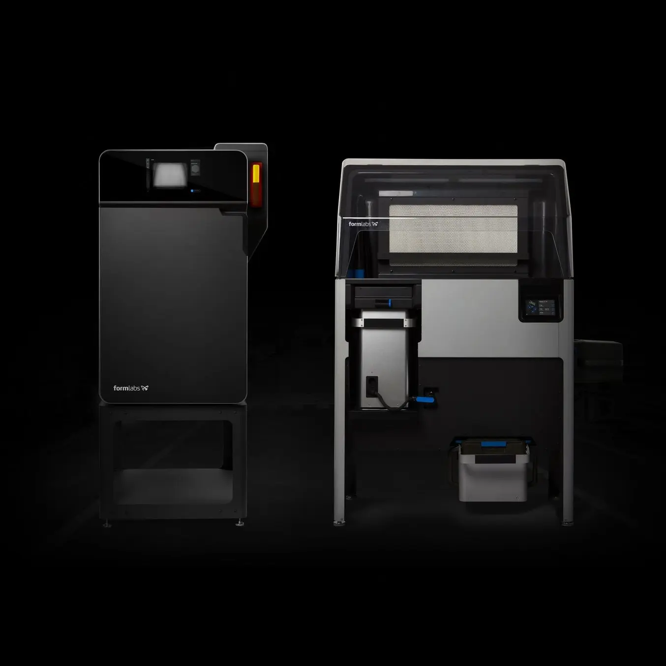
SLA printers like Formlabs Form 4 and Form 4L offer a range of material properties, from highly soft and flexible elastomers like Elastic 50A Resin or Silicone 40A Resin to extremely rigid options like Rigid 10K Resin or High Temp Resin. Depending on the desired function of the joint, you can choose a resin that either holds the joint immobile or allows for slight movement and easy disassembly of the joint.
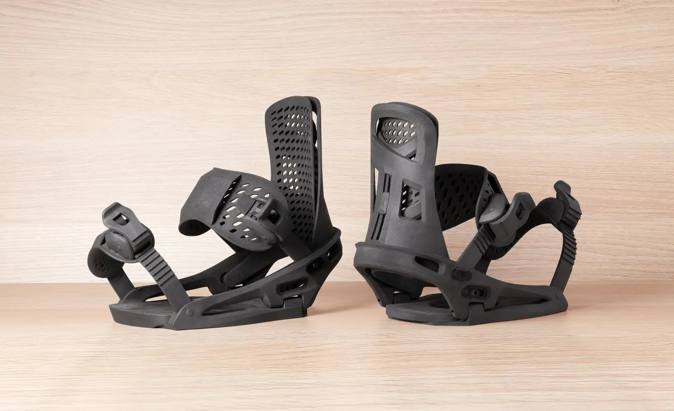
SLS 3D printers like Formlabs’ Fuse Series have the advantage of using industry-standard plastics such as nylon and TPU. Because of the strength of these materials, and the lack of supports necessary to create intricate features with overhangs, recesses, channels, and fins, SLS 3D printing is perhaps the most ideal method for creating interlocking assemblies.
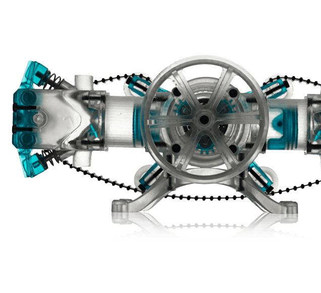
Another potential solution for 3D printing interlocking joints is the combination of multiple types of 3D printed interlocking joints and features. Here, you can see a fully print-in-place vise 3D printed on the Fuse 1+ 30W SLS 3D printer in Nylon 12 Powder and Form 4 using Elastic 50A Resin for the soft jaws.
Forces Acting On a 3D Printed Interlocking Joint
Interlocking joints are designed to hold pieces together against the forces acting upon them, which could be gravity or active energy pulling the two pieces apart (e.g., a chain link could be holding a weight to a fixture, acting against gravity, or, a chain link could be holding two train cars together, both pulling in opposite directions). Though these forces can be categorized by their energy source, like gravity, we instead label them by the type or direction of stress they put on the joint itself.
-
Friction: The main force holding a joint together. By decreasing your clearances and tightening tolerances, you’ll increase your friction and the interlocking joint will be held together more tightly.
-
Tension: The main force acting against your joint, trying to pull it apart.
-
Shear: The secondary force acting perpendicular to the direction of the tension, a sideways tearing force.
Step By Step Guide to Designing 3D Printed Interlocking Joints
Nylon 12 Powder Jig: Interlocking Bit
To design this interlocking bit design:
-
Designate your general workspace (the specific area on the part where the joint will be)
-
Create one side of your interlocking joint feature, and choose an angle for your cut-out that makes sense for your part — here we chose a 65-degree angle.
-
Mirror your cut-out on the other side of the interface
-
Off-set your cut-out, choose 0.2 mm for small parts, and 0.4 mm for larger parts. This will give you the tolerance of the joint so it can print cleanly.
-
Close your loops to get the cut-out that you can extrude through your part.
-
Adjust your joint to make sure the extrusion lines up through the part.
-
Pattern your interlocking joint elsewhere on your part so that you can separate the big part into multiple smaller parts for easier/more efficient printing and packing.
Nylon 12 Powder Chain Hackey Sack:
To design this interlocking ringed hackey sack:
-
Sketch out a simple ring (you can create arbitrary-sized rings and then scale to an appropriate size in PreForm).
-
Place one ring flat.
-
Pattern your ring next to your first, and drag the second ring to interlock with the first, leaving a .2 mm distance at minimum between their surfaces.
-
Choose both rings and pattern again, interlocking all four and building up and to the side.
-
Continue patterning until you create an enclosed sphere of rings.
-
Import into PreForm and scale to desired size, duplicate, and pack vertically if necessary for higher volumes of parts.
Nylon 12 Powder Tablet Holder
To design this tablet holder for a conference room tablet organizer:
-
Import the dimensions of your device: length, width, height, and depth. Insert these dimensions into your sketch. You’ll be able to see the overall dimensions of the device. Move the dimensions out of the way for better visibility.
-
Add space for tolerancing. For the Fuse 1+ 30W, 0.2 mm tolerance is good for thinner, less bulky parts like this. Less space than this for tolerancing will make this part a more press-fit style, which will be more difficult to disassemble.
-
Make a new sketch on the top face. Create one side, then mirror it to the other side. Create an interlocking joint with a simple dovetail joint. Extrude your sketch.
-
Ensure your gap (tolerance) runs all the way through the joint.
-
Determine if your parts will slide together or if they will be glued together. If the latter, use a cyanoacrylate or a two-part epoxy. Apply thoroughly, as a small amount of glue will be absorbed into the surface.
3D Printing Interlocking Parts and Assemblies
As shown in our examples, designing simple interlocking features for 3D printing can be quite easy. The main thing to keep in mind when designing interlocking joints for 3D printing is that you need to factor in the tolerance of the 3D printing technology and material, and consider what type of part you’re printing, whether it’s very large and chunky or smaller and thinner. These considerations will impact your tolerances — though both Formlabs SLA and SLS have tight tolerances and high, repeatable accuracy — and you can adjust your design accordingly.
For smaller, thinner parts, you can use a 0.2 mm tolerance gap when designing multi-piece assemblies with interlocking parts. For larger, chunkier assemblies, it is wise to make your tolerances a bit larger, up to 0.4 mm.
Formlabs’ SLS printer, the Fuse 1+ 30W, is ideal for printing interlocking parts that are print-in-place like the chain mail hackey sack part in the second example. You’re able to print interlocking rings of material without supports, and can post-process it easily in the Fuse Blast, without hands-on labor to remove unsintered powder from between the rings.
Formlabs SLA printers, like Form 4 and Form 4L, are good for printing parts with extremely sharp edges and smooth surfaces, which come in handy for parts that need to slide together with minimal friction.
To learn more about Formlabs SLA and SLS 3D printers, visit our website. You can receive a free 3D printed SLA or SLS sample part with interlocking features by requesting a sample on our website.
Not sure which 3D printing solution fits your business best? Book a 1:1 consultation to compare options, evaluate ROI, try out test prints, and more.