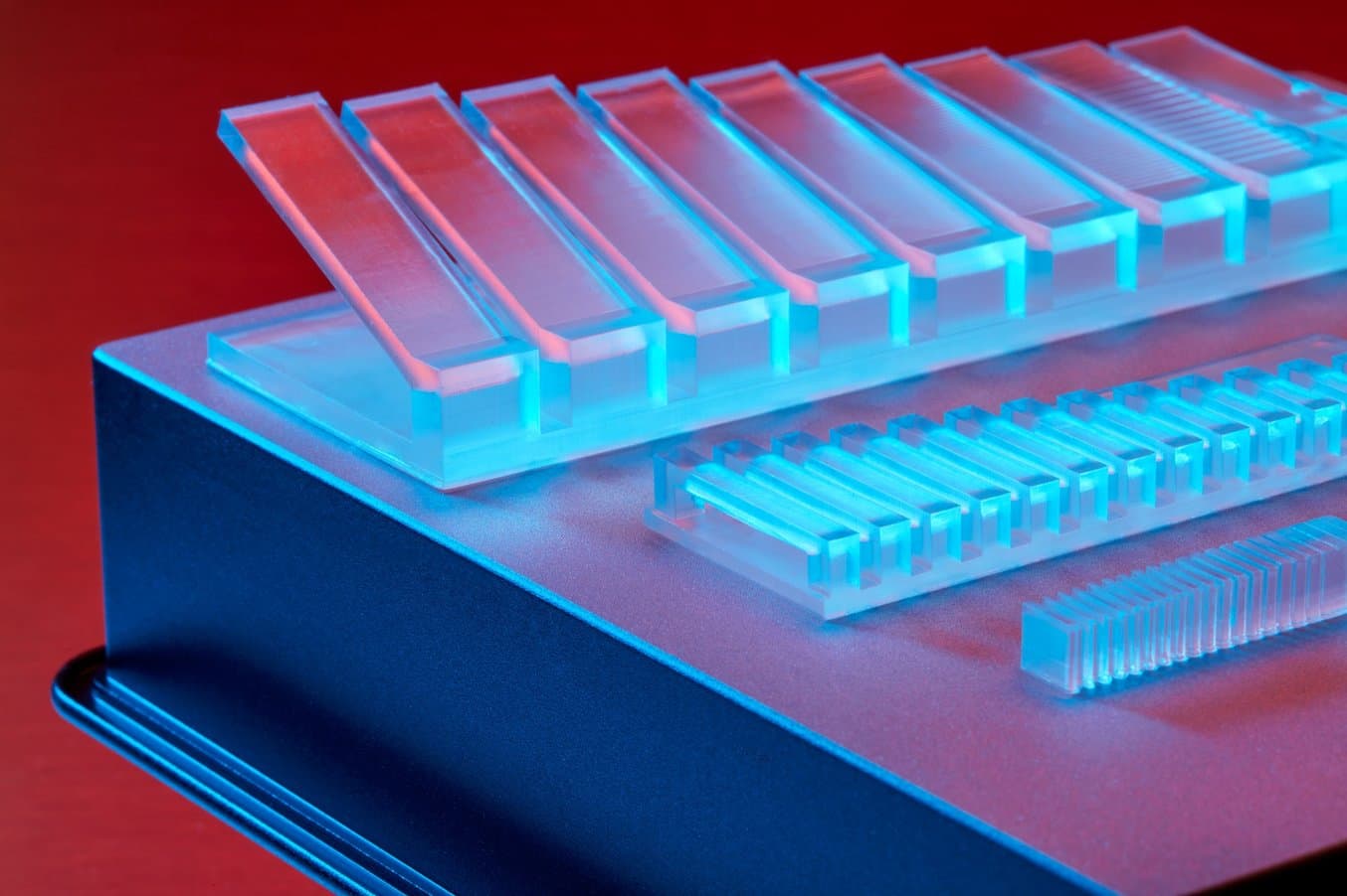
For many designers and creators, Formlabs printers represented their first foray into the world of in-house stereolithography (SLA) 3D printing. In line with other manufacturing processes, 3D printing has limits on what can be produced using this technology. With the introduction of Low Force Stereolithography (LFS), the Form 3 expands what can be printed using SLA 3D printing.
Formlabs created a Form 3 design guide which can be used as a reference guide when creating new designs that may expand beyond the boundaries of what the Form 3 is capable of producing. This includes how long overhangs should be without supports, or the minimum size for drain holes. Formlabs engineers designed a series of STL files to stress test the Form 3 printer, pushing the designs until they failed. The results are recorded in the design guide. All tests for the Form 3 design guide were completed using Clear Resin at 100 micron resolution. We believe that Clear Resin prints demonstrate what our resin library is capable of, but designers should expect some variations when using other materials.
The Form 3 is capable of printing more geometrically challenging designs than most 3D printers on the market. This includes a targeted improvement when it comes to surface finish, detail, and time savings over our previous printer, the Form 2. Low Force Stereolithography (LFS) 3D printing uses a flexible resin tank to significantly reduce peel forces during printing and a Light Processing Unit (LPU), our custom-designed enclosed optics engine, to produce consistent, accurate prints. The greater level of consistency achieved with LFS means the Form 3 can repeatedly and successfully print objects at tighter printing parameters than previously possible.
The parameters covered in the Form 3 design guide include:
- Maximum unsupported overhang length, unsupported overhang angle, and horizontal support bridges.
- Minimum supported wall thickness and minimum unsupported wall thickness.
- Vertical-wire diameter, embossed detail, engraved detail, clearance, hole diameter, and drain hole diameter.
Here are some examples of how the Form 3 can improve your design:
Minimum Hole Diameter
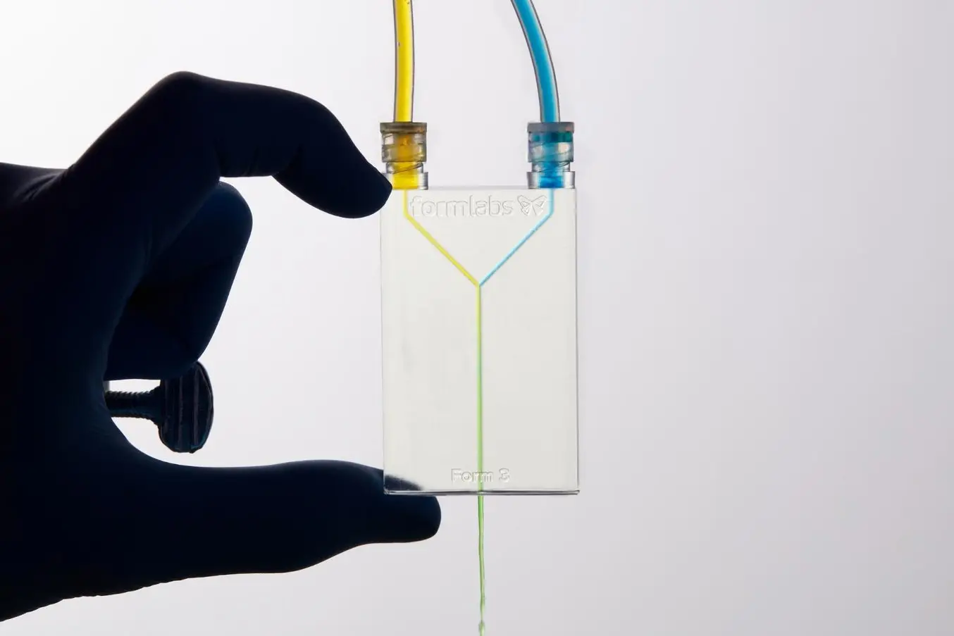
Small holes in a 3D print have many uses, such as millifluidic chips. However, if holes are created too small, then the resin may cure and clog the opening, preventing fluid flow.
Holes with a diameter less than 0.5 mm in the x, y, and z axes may close off during printing, unless special care is taken during their design and orientation within PreForm. For comparison, the Form 2 is capable of producing a minimum hole diameter of 0.8 mm. This is slightly smaller than a standard FDM printer, which can create holes as small as 1.0mm.
Minimum Engraved Detail
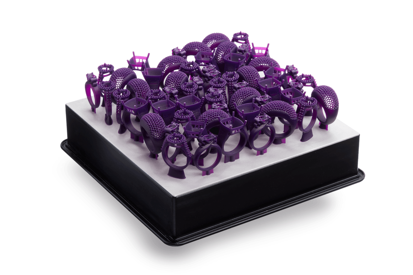
Engraved details are imprinted or recessed features on your model. This could include adding vehicle identification codes to engines, or other identification codes to parts. You also find this feature critical for jewelry, enabling the addition of hallmarks and purity information or the engraving of names and personal messages.
Details recessed less than 0.15 mm in thickness and in height may not be visible because they will be fused with the rest of the model during the print process. For comparison, the minimum engraved detail capable on the Form 2 is 0.4 mm.
Overhangs
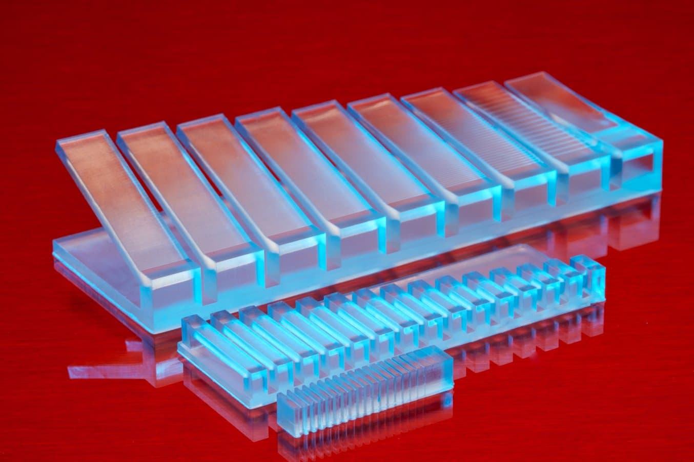
Overhangs are surfaces of a 3D print that stick out horizontally parallel to the build platform, such as the sides of a box or the wrap-around sections of an iPhone case. We still recommend turning on internal supports in PreForm where possible in order to reduce the likelihood of failure, but the Form 3 is capable of printing up to 5 mm wide unsupported overhangs. For comparison, the Form 2 is capable of producing maximum overhang of only 0.2 mm.
Oftentimes, design constraints are not obvious. For example, the screw threads above are a type of overhang. PreForm has a built-in tool called the slicer (the slide bar on the right hand side), which allows users to view each layer of a model individually. As slicer is used, users can visually see how overhangs will print, and if supports are necessary.
Download the Form 3 Design Guide
To see the specific design constraints that our engineers recommend, click here to download the Form 3 Design Guide.
Formlabs offers an extensive support documentation for all of our 3D printers. deep support network for assistance with any of our 3D printers. If you are looking for additional information about your Form 3 printer, please check out our support website.
