
Occipitocervical instrumented fixation utilising patient-specific C2 3D-printed spinal screw trajectory guides in complex paediatric skeletal dysplasia
Introduction
“Instability of the craniocervical junction in paediatric patients with skeletal dysplasia poses a unique set of challenges including anatomical abnormalities, poor bone quality, skeletal immaturity and associated general anaesthetic risks.

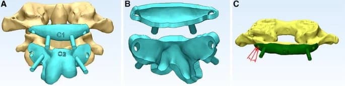
3D reconstruction of the cervical vertebra. Arrows depict the deformity secondary to anterolisthesis of C1.
Instrumented fixation provides optimal stabilisation and fusion rates. The small vertebrae make the placement of C2 pedicle screws technically demanding with low margins of error between the spinal canal and the vertebral artery. We present two cases in which a 3D-SSTG (3D-printed spinal screw trajectory guides) has been used to facilitate safe occipito-cervical fusion with bilateral C2 pedicle screw placement in the first case and bilateral C2 laminar screw placement in the second.”
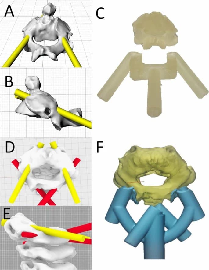
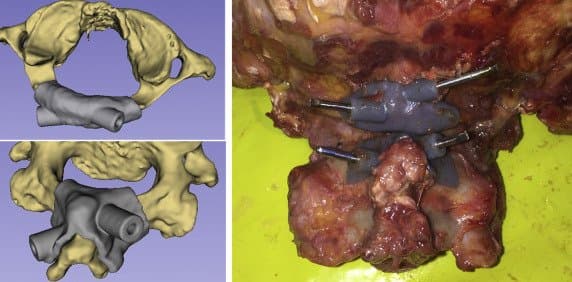
Case 1: 3D reconstruction of C2 from posterior (A) and lateral (B) views depicting planned pedicle screw trajectories to maximise distance from the spinal cord and high riding vertebral artery. 3D-printed spinal screw guide and corresponding C2 vertebral model (C).
Case 2: 3D reconstruction of C2-4 from superior (D) and lateral (E) views depicting the planned C2 pedicle (yellow) and laminar (red) screw trajectories. Due to the high riding vertebral artery, there was no potential to place a 3.5-mm diameter screw without breaching into the vertebral foramen or breaching the superior aspect of the pars. A laminar screw trajectory was consequently incorporated into the same trajectory guide (F).
Methods and Materials
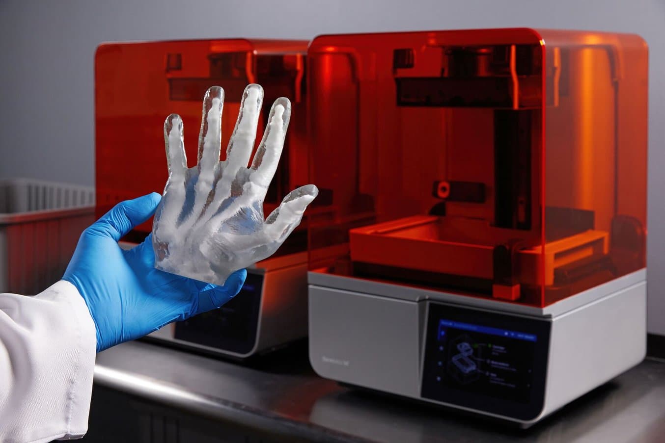
“The technique is based on a pre-operative CT scan and does not require intraoperative CT imaging. This reduces the radiation burden to the patient and forgoes the associated time and cost.The 3D-SSTGs were printed in “BioMed Amber Resin” on the Formlabs 3B (Formlabs Inc., Somerville, MA) biomedical printer. The models were then washed in 99% ethanol before UV curing and removal of support structures. Sterilisation was then undertaken following: autoclave sterilisation protocol of 3 min at 138 °C. The time for model generation and sterilisation was < 24 h.”
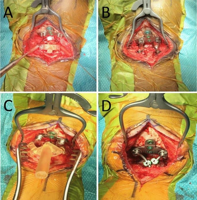
Intraoperative use of drill guides. Intraoperative images revealing placement of the 3D-printed spinal screw trajectory guide placed on the back of the C2 vertebra for case 1 (A) and 2 (C). The occipital plate and C1 laminectomy had already been performed. Final image after insertion of the laminar screws and connection to the occipital plate through rods bilaterally (B and D).
Results and Discussion
“We describe two patients (three and six years old) requiring occipitocervical instrumented fixation for cervical myelopathy secondary to Morquio syndrome with 3D-SSTGs. In the second case, bilateral laminar screw trajectories were also incorporated into the same guide due to the presence of high-riding vertebral arteries. Registration of the postoperative CT to the pre-operative imaging revealed that screws were optimally placed and accurately followed the predefined trajectory. Both patients had an uneventful recovery from surgery and were discharged from hospital on postoperative day 4. At 5 months following surgery, neither patient developed any infection or wound related complication.”
Conclusion
“To our knowledge, we present the first clinical report of 3D-printed spinal screw trajectory guides at the craniocervical junction in paediatric patients with skeletal dysplasia. The novel combination of multiple trajectories within the same guide provides the intraoperative flexibility of potential bailout options. Future studies will better define the potential of this technology to optimise personalised non-standard screw trajectories.”
Formlabs Biocompatible Resins: A Comprehensive Guide To Choosing the Right Material
Formlabs currently offers more than 40 unique materials for stereolithography (SLA) 3D printing. This paper helps users compare and contrast our biocompatible offerings, and determine the best fit for their medical applications.
Accuracy assessment of atlantoaxial pedicle screw placement assisted by a novel drill guide template
Introduction
“Posterior atlantoaxial pedicle screw fixation is an effective technique for atlantoaxial instability (AAI). However, because of the complex anatomy of the cranio-cervical junction, it remains challenging to insert atlantoaxial pedicle screw precisely and safely. A novel drill guide template was designed for atlantoaxial pedicle screw placement in this study. The purpose of this study is to quantitatively evaluate the accuracy of atlantoaxial pedicle screw placement using the novel drill guide template.”
Methods and Materials
“Between June 2014 and September 2015, 32 consecutive patients with AAI were included… a novel drill guide template with two location holes and guide rods was designed [and printed on the Form 1+ using a third-party resin. All patients underwent posterior atlantoaxial pedicle screw fixation assisted by the novel drill guide template. After surgery, the entry point and directions of actual and ideal screw trajectories were measured and compared.”
A and B Novel drill guide template with two location holes and guide rods. C Screw trajectory can be acquired by drilling through the location hole and parallel to the guide rod of the template. If the actual trajectory deviated from the ideal trajectory, drill direction can be adjusted based on the guidance of the template.
Results and Discussion
“All patients underwent surgery successfully assisted by the novel drill guide template. A total of 128 atlantoaxial pedicle screws were placed for 32 AAI patients. Postoperative CT scans showed two screws in atlas deviated medially from the pedicle cortex and entered the spinal canal about 1 mm but without symptoms. For both atlas and axis, there were no significant differences in entry point or directions between the ideal and actual screw trajectories (P > 0.05). Significant differences were found in preoperative and postoperative Japanese Orthopaedic Association score and Visual Analogue Score (P < 0.001).”
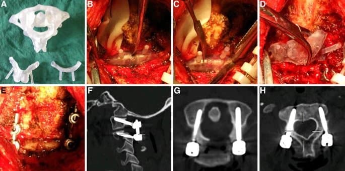
A Atlantoaxial model and the novel template were produced by rapid prototyping technique. B Template for C1 was placed on the bony surface. C Screw trajectory was acquired by drilling through the location hole and parallel to the guide rod of the template. D Template for C2 was placed. E atlantoaxial pedicle screws were inserted. F-H Good positioning of atlantoaxial pedicle screws was shown in postoperative sagittal and axial CT scans.
Conclusion
“It is feasible to use the novel drill guide template for atlantoaxial pedicle screw placement. The accuracy of screw placement assisted by the novel template is high. More studies are needed to confirm the efficacy of this template.”
Accuracy of Patient-Specific Drill Guide Template for Bilateral C1-C2 Laminar Screw Placement: A Cadaveric Study
Introduction
“Different screw placement techniques have been described for atlas and axis. The Harms screw placement technique is the most common surgical intervention for stabilizing the atéantoaxial. However, C1 lateral mass and C2 pedicle screw placement remain technically difficult due to the proximity of neural structures and the location and anatomic variation of the vertebral artery around C1 and the foramen transversarium of C2”
“We sought to evaluate the accuracy of using patient-specific drill guides to place bilateral laminar screws in C1 and C2.”
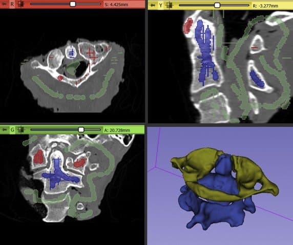
Each C1 and C2 vertebral body was individually segmented using the “paint” and semiautomated “grow-from-seeds” function in 3DSlicer.
Methods and Materials
“Nine cervical specimens (8 males; mean age: 66.6 [56−73]) with the occiput attached (C0-C3) were used in this study. Preoperative computed tomography (CT) scans were used to create digital anatomic models for templating and guide creation. A total of 36 screws were placed with the aid of 3-dimensional printed, patient-specific guides (2 screws at C1 and C2). Postoperative CT scans were performed following screw insertion. The planned and actual trajectories were compared using preoperative and postoperative imaging based on the angular and entry point deviation. After screw placement and postoperative imaging, each specimen was dissected and performed a visual inspection for breaches.”
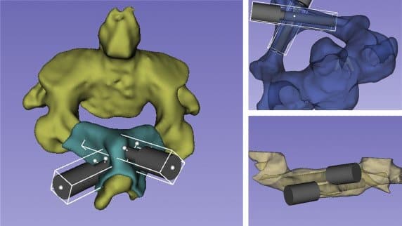
Cylinders used during the trajectory planning before the Boolean operations were performed to create the final drill guide. The opacity of the 3D bone model was reduced to allow internal visualization.
“The digitalized implants were exported as 3D models in STL format into the printer's dedicated software (FormLabs Preform) and 3D printed using a stereolithography printer (Form 2, FormLabs, Somerville, Massachusetts, USA)... Grey Pro resin was used as this type of resin allows moderate elongation and is not prone to deformation over time, making it an ideal candidate as a guide material.”
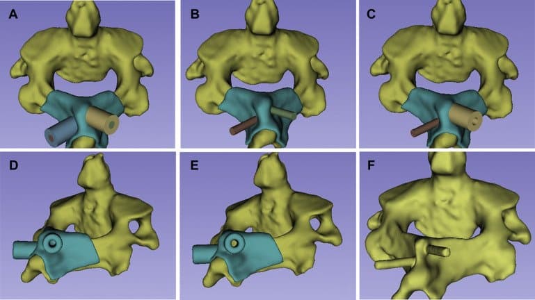
Images show the steps used during the Boolean operations to create the final patient-specific guides (A−E) for each bone and also the 3D model that would be used later for the trajectory comparison (F).
Results
“No breaches or violations were observed on postprocedural CT and visual inspection. The average variation of the entry point in the X, Y, and Z axes was 0.3 ± 0.28, 0.41 ± 0.38, and 0.29 ± 0.24, respectively. No statistically significant difference (P > 0.05) was observed between the planned and obtained entry points. There was no significant difference (P > 0.05) in the deviation analysis between the planned and obtained angles in the axial and coronal planes.”
Images show the final aspect for the C1 (top left) and C2 (bottom left) guides. The right side picture shows the patient-specific guides attached to the bone and the K-wires used to record the obtained trajectory on the postprocedural CT scan.
Discussion
“To our knowledge, this is the first study to create a bilateral C1 lamina patient-specific drill guide that avoids extensive dissection of the soft tissue… In this study, we chose to use clinically available CT scanners and an affordable commercially available desktop 3D printer to demonstrate the feasibility of the guide for clinical use in a variety of hospitals. The FormLabs Form2 printer was able to fabricate a guide that had excellent screw accuracy and excellent qualitative fit to anatomy... ”
Conclusion
“The study demonstrates that patient-specific drill guides allow for accurate C1 and C2 bilateral laminar screw placement, with a low risk of cortical breach.”
The Development of Novel 2-in-1 Patient-Specific, 3D-Printed Laminectomy Guides with Integrated Pedicle Screw Drill Guides
Introduction
“Laminectomy is the mainstay of treatment for conditions that require spinal decompression of the neural elements, such as spinal stenosis, spondylolisthesis, intervertebral disc herniation and fracture. Despite being a very common procedure, traditional laminectomy has several risks, including dural tear, damage to neural elements, and spinal instability, as a result of iatrogenic spondylolisthesis… To our knowledge, the use of patient-specific guides has not been applied to laminectomy… Objective of the study: To determine if 2-in-1 patient-specific laminectomy and drill guides can be safely used to perform laminectomy and pedicle screw insertion.”
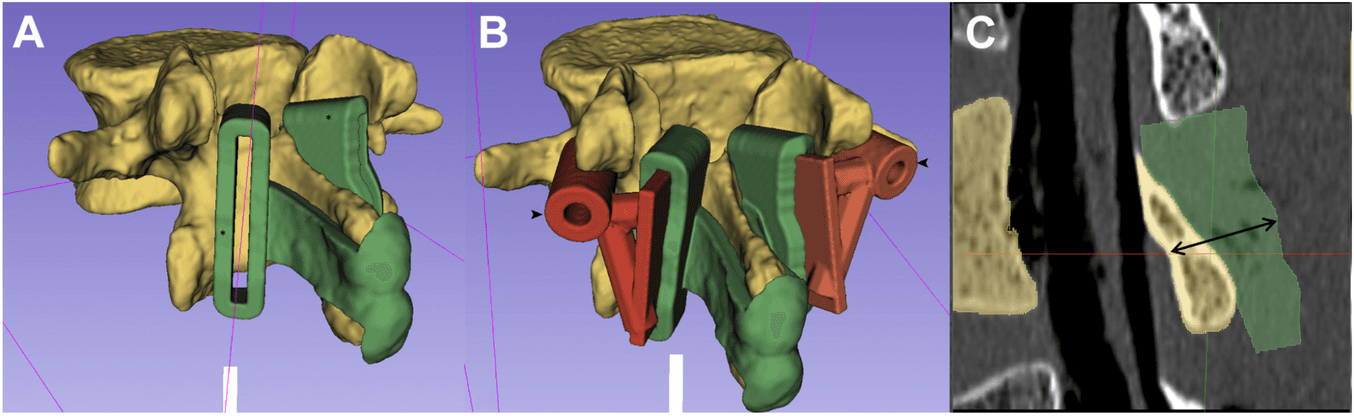
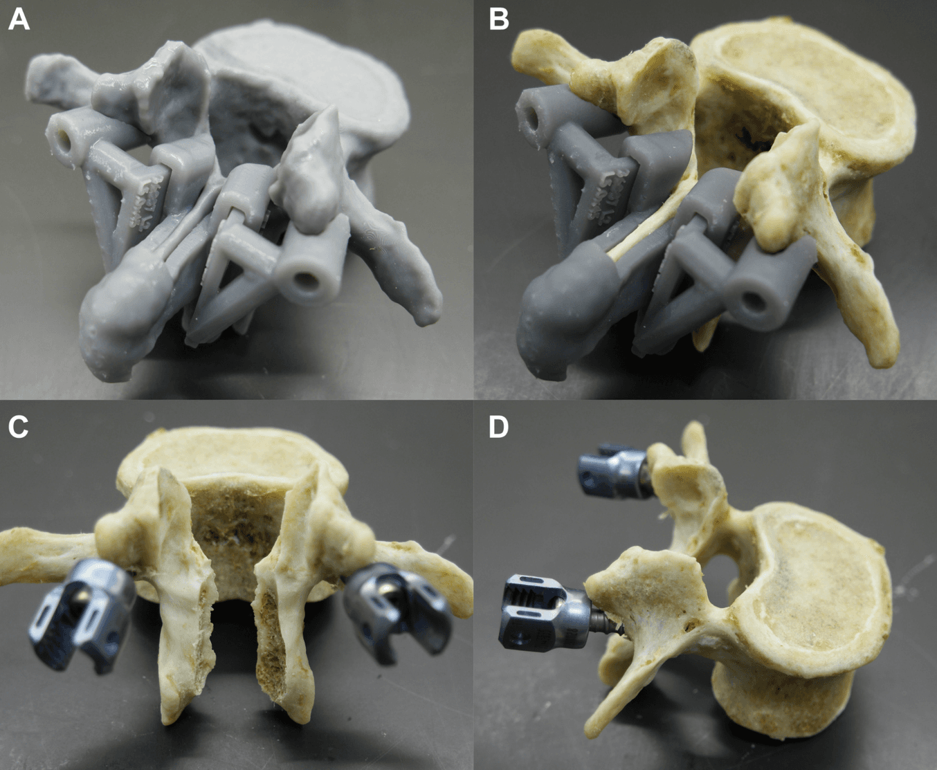
(A) A vertebral model and laminectomy guide were created using 3D Slicer. (B) Drill guides (arrowhead) were created and joined to removable slots, which fit into the laminectomy guides, to create a 2-in−1 guide. (C) Sagittal reconstruction demonstrating the 14-mm depth-stop design (double arrow). The dorsal contour of the laminectomy guides was created to match the deep surface of the lamina, set at a depth of 14 mm.
Methods and Materials
“This was a cadaveric study designed to test novel 2-in-1 patient-specific laminectomy guides, with modular removable pedicle screw drill guides… Computed tomography (CT) scans of 3 lumbar spines were imported into 3D Slicer. Spinal models and patient-specific guides were created and 3D printed… using Formlabs Form 2 (Formlabs Inc.) desktop 3D printer using Grey Pro Resin (Formlabs Inc.). The bones were cleaned to visualize and record the under surface of the lamina during laminectomy. Pedicle screws and laminectomies were performed with the aid of patient-specific guides. CT scans were performed to compare planned and actual screw and laminectomy positions.”
Results
“Thirty screws were inserted in 15 lumbar vertebrae by using the integrated 2-in-1 patient-specific drill guides. There were no cortical breaches on direct examination, or on postoperative CT. Digital video analysis revealed the burr tip did not pass deep to the inner table margin of the lamina in any of the 30 laminectomy cuts. Average surgical time was 4 minutes and 46 seconds”
Discussion
“Pedicle screw insertion and laminectomy are 2 of the most common and complex steps performed in spinal surgery….Recent advances in intraoperative navigation systems have allowed for intraoperative 3D image acquisition, which increases accuracy of instrumentation placement. The overall reported rate of screw malposition is 8.5%–11% using navigation techniques. Several weaknesses of these systems include a significant learning curve; exposure to radiation; optical array devices that can be displaced; and high cost…In this study, 2-in-1 patient-specific laminectomy guides, with integrated pedicle screw drill guides, were used to perform these complex and time-consuming steps safely and efficiently. The pedicle screws and laminectomies were performed accurately, with safety of laminectomy confirmed by ensuring the burr tip did not travel deep to the inner table margin of the lamina.”
Conclusion
“This study has explored the development of novel 2-in-1 patient-specific, 3D-printed laminectomy guides with integrated pedicle screw drill guides, which are accurate and safe in the laboratory setting. These instruments have the potential to simplify complex surgical steps, and improve accuracy, time, and cost.”
Generating patient-matched 3D-printed pedicle screw and laminectomy drill guides from Cone Beam CT images: Studies in ovine and porcine cadavers
Introduction
“The emergence of robotic Cone Beam Computed Tomography (CBCT) imaging systems in trauma departments has enabled 3D anatomical assessment of musculoskeletal injuries, supplementing conventional 2D fluoroscopic imaging for examination, diagnosis, and treatment planning. To date, the primary focus has been on trauma sites in the extremities….The purpose of this study is to determine if CBCT images can be used during the treatment planning process in spinal instrumentation and laminectomy procedures, allowing accurate 3D-printed pedicle screw and laminectomy drill guides to be generated for the cervical and thoracic spine.”
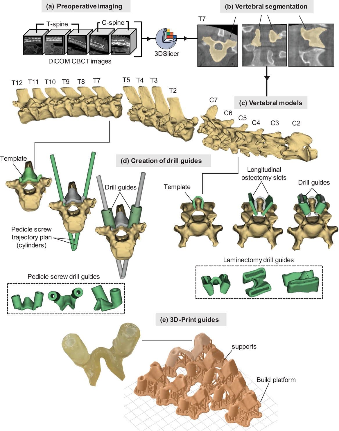
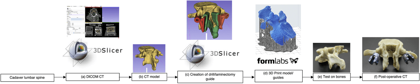
Development process for 3D-printed drill guides from CBCT images. (a) Preoperative CBCT imaging. (b) Vertebral segmentation in 3D-slicer. (c) Developing the vertebral models. (d) Creation of drill guides (pedicle and laminectomy). (e) 3D-print guides
Methods and Materials
“The accuracy of drill guides generated from CBCT images was assessed using animal cadavers (ovine and porcine). Preoperative scans were acquired using a robotic CBCT C-arm system... The CBCT images were imported into 3D-Slicer version…The patient-matched pedicle screw guides and laminectomy guides, as well as the vertebral biomodel files, were imported into Formlabs Preform software version 3.0.2 (Formlabs Inc., Somerville, MA, USA) to be printed using Formlabs Form 2 (Formlabs Inc.) desktop 3D printer using Surgical Guide resin (Formlabs Inc.)... The Surgical Guide Resin is fully biocompatible and can be steam sterilized using an autoclave, allowing it to be used safely in the clinical setting…In the ovine cadaver, 11 [thoracal] pedicle screw guides and 6 [cervical] laminectomy guides… In the porcine cadaver, nine pedicle screw guides… were planned and printed… accuracy was assessed by three observers according to pedicle breach”, remaining lamina thickness (guides were designed to leave 1 mm of lamina), and mean axial and sagittal screw error via postoperative CBCT and CT scans…For all measurements, the intraclass correlation coefficient (ICC) was calculated to determine observer reliability.”
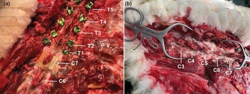
(a) spine prior to laminectomy cuts with the guide for the C7 vertebra resting on the spinous process and (b) following the laminectomy on the C3–C7 cuts
Results
“Compared with the planned screw angles for both the ovine and porcine procedures (n = 32), the mean axial and sagittal screw error measured on the postoperative CBCT scans from three observers were 3.9 ± 1.9° and 1.8 ± 0.8°, respectively. The ICC among the observers was 0.855 and 0.849 for the axial and sagittal measurements, respectively, indicating good reliability. In the ovine cadaver, directly comparing the measured axial and sagittal screw angle of the visible screws (n = 14) in the postoperative CBCT and conventional CT scans from three observers revealed an average difference 1.9 ± 1.0° in axial angle and 1.8 ± 1.0° in the sagittal angle. The average thickness of the lamina at the middle of each vertebra, as measured on-screen in the postoperative CBCT scans by three observes was 1.6 ± 0.2 mm. The ICC among observers was 0.693, indicating moderate reliability. No lamina breaches were observed in the postoperative images.”
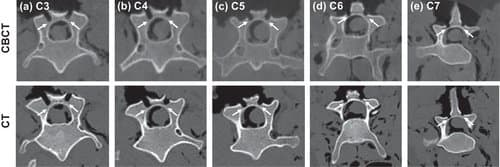
Postop. CBCT (top) and CT (bottom) images of the cervical vertebra (a)–(e). White arrows indicate the remaining lamina.
Conclusion
“Here, CBCT images have been used to generate accurate 3D-printed pedicle screw and laminectomy drill guides for use in the cervical and thoracic spine. The results demonstrate sufficient precision compared with those previously reported, generated from standard preoperative CT and MRI scans, potentially expanding the treatment planning capabilities of robotic CBCT imaging systems in trauma departments and operating rooms.”
Empowering Innovation in Healthcare
To discover more about the Formlabs medical printers and materials, or to see further peer-reviewed research, visit our medical page or contact our medical sales team.