
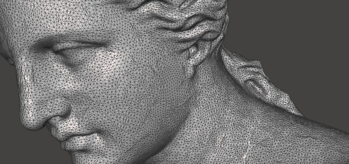
Before 3D printing a part, designers and engineers often need to adapt, optimize, finalize, and edit 3D models. Autodesk’s Meshmixer is a state-of-the-art software for working with triangle meshes or, as its developers like to call it, the "Swiss Army Knife" for editing STL files and 3D meshes.
With Meshmixer, it’s not only possible to optimize a triangle mesh but also to resculpt entire sections, stylize the model, or add useful features to it.
And the best news? Downloading MeshMixer is completely free.
This guide walks through 15 pro tips for both beginner and advanced users to empower designers to change their 3D models with this versatile software.
Book a Free Consultation
Get in touch with our 3D printing experts for a 1:1 consultation to find the right solution for your business, receive ROI analyses, test prints, and more.
Tip #1: Importing and Exporting
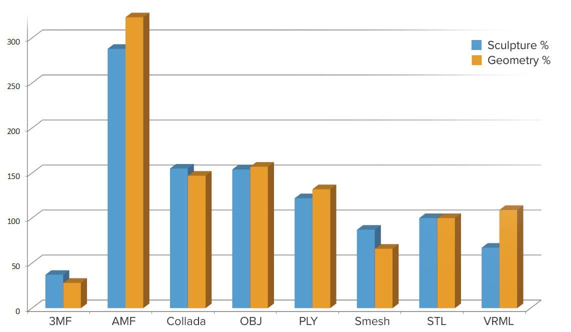
At the start of a project, choose a file format that can comprehensively describe the design while suiting the intended applications and minimizing the need for file conversions. Meshmixer will read numerous 3D file types, such as STL, OBJ, PLY, and some lesser known formats; AMF, 3MF, OFF, and the native MIX format. For exporting designs to a different format, Meshmixer also supports Collada, VRML, and Smesh.
- STL (STereoLithography) is a format originally developed for stereolithography 3D printing that is the most commonly accepted file format in 3D printing. It stores only geometry data and has a compact file size.
- OBJ as first created by Wavefront is a simple format storing vertex information to represent a 3D mesh. Besides vertex positions, it also stores surface normal plus a UV coordinate that can be mapped to an external texture.
- PLY (Polygon) is a more extensive format developed at Stanford to aid the storage of 3D scanning data. One of its benefits is the possibility to assign properties such as texture data separately for both sides of a face.
- AMF (Additive Manufacturing Format) is an alternative to STL for 3D printing. Being XML-based, it will store additional data such as orientation, scale, patterning multiple objects, non-planar edges, and graded materials.
- 3MF (3D Manufacturing Format) is similar to AMF but less standardized as it is created by a consortium of companies. Originally developed by Microsoft, it is the native 3D format in Windows.
- OFF (Object File Format) is a simple, hand-programmable, text-based format that next to geometry also stores color data per vertex.
- Collada (COLLaborative Design Activity) is a versatile format well-suited for digital assets that was developed by Sony. The now widely supported format allows developers to store rendering data such as animations, level-of-detail, shaders, as well as diffuse, normal and specularity maps.
- VRML (Virtual Reality Markup Language) is similar to Collada but scriptable and compatible with web browsers.
- Smesh is a simple format that describes 3D geometry both in terms of triangles and complex polygons. This makes the format more suited for objects with large planar areas.
Tip #2: Remeshing
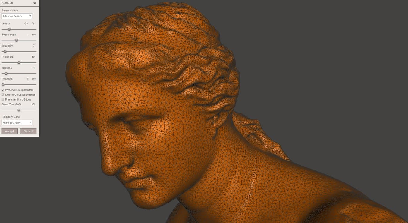
Before modifying a part, make sure to optimize its triangulation. In our example, we picked a model of the Venus of Milo that has an uneven distribution of triangles plus some split and collapsed triangles. With Meshmixer, you can create an even tessellation using the Remesh command.
Click the Select Icon in the menu and click to create an area to be remeshed, or use Ctrl + A to select the entire object. On the Popup menu, click Edit → Remesh or hit R. There are several Remesh Modes:
-
Target Edge Length ensures an even triangle size across the mesh, optimizing the part for sculpting. This is computationally intensive so set a reasonable size relative to the object.
-
Relative Density is the same method but specifies according to triangle density.
-
Adaptive Density creates a denser triangulation in more detailed areas, optimizing file size. This is helpful when the object is complete and can be saved for 3D printing.
-
Linear Subdivision simply creates more triangles by splitting existing ones, maintaining the original geometry.
Note that the Regularity setting creates more equilateral triangles but sacrifices more detail. The Transition setting creates a gradual transition from the original mesh to the remeshed section. With Preserve Group Boundaries checked the program maintains the shape of specifically designed triangle groups such as perfectly round eyes. Checking the Preserve Sharp Edges option prevents hard corners from being smoothed out. Under Boundary, a Free Boundary is often preferred because it sacrifices accuracy for mesh quality.
Tip #3: Separating Sections
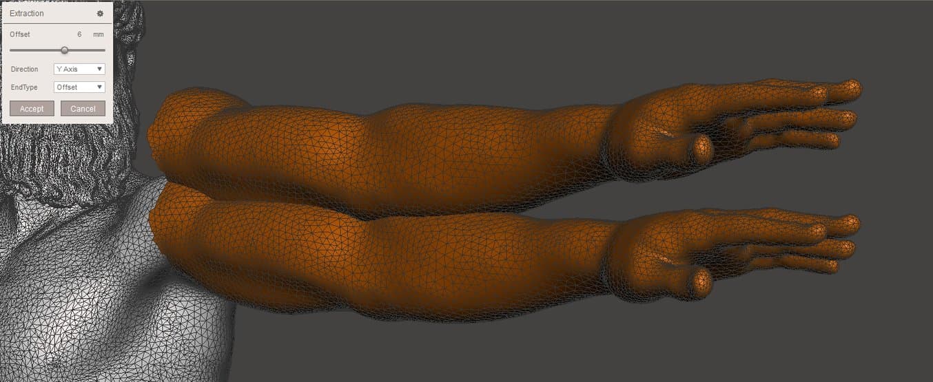
Meshmixer offers several ways to separate a part of a mesh. The simplest method is first selecting the part to be separated, then using the Edit → Extract (Shift+D) command. The program will create a new shell with an optional offset distance. Choosing the Normal direction for the offset will expand or shrink your part. Then, from the main menu, pick Edit → Separate Shells to individually save and name each part, while deleting obsolete sections.
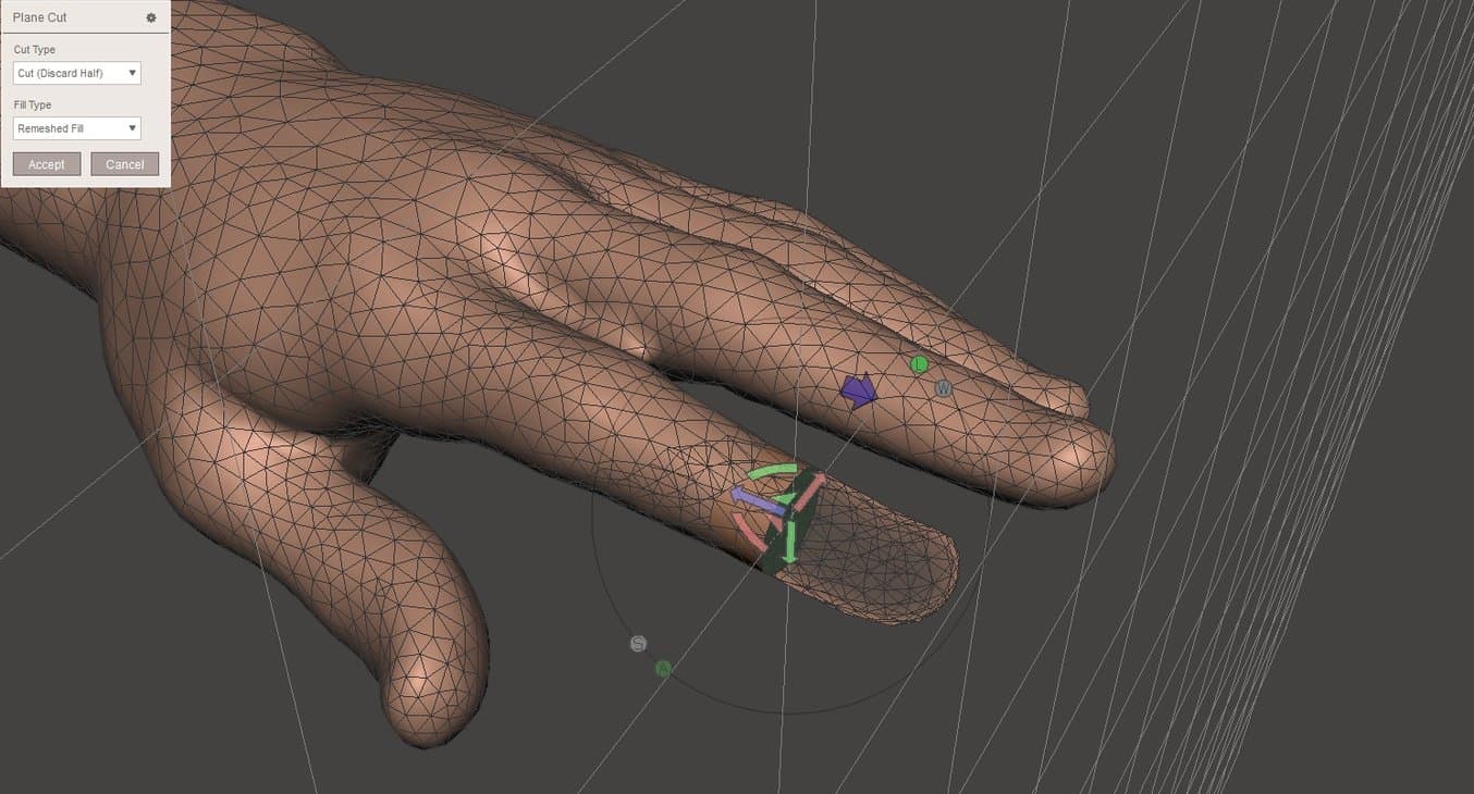
The other method is Edit → Plane Cut. This brings up a transform gizmo allowing orientation of the cutting plane. The blue arrow is used to specify cutting direction. In case a plane would cut off unwanted sections, it is possible to create a selection prior to cutting. With the selection active, hit Edit → Plane Cut from the pop-up rather than from the main menu.
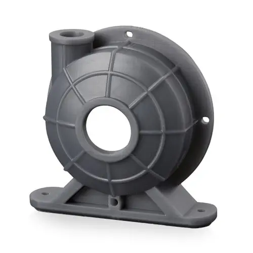
Request a Free Sample Part
See and feel Formlabs quality firsthand. We’ll ship a free 3D printed sample part to your office.
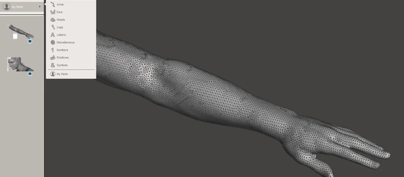
Tip #4: Creating a Custom Library
Meshmixer was originally created to interchange and combine different 3D parts. On opening the program, the first icon Meshmix opens up a library of parts. Under the dropdown menu is a section called My Parts. This allows users to create a custom 3D library.
To add an object, select it in the object browser (toggle with Ctrl + Shift + O), then select all with Ctrl + A. Now in the Select section of the main menu choose Convert to → Solid Part. After hitting Accept the object will be visible in the My Parts section.
Tip #5: Sculpting Basics
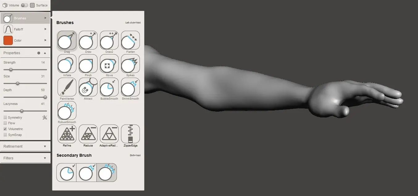
In the Sculpt section, Meshmixer offers several brushes that can be applied directly to the mesh. The following Volume brushes offer all the functionality required for basic 3D sculpting work:
-
Drag moves an area in 3D space
-
Draw displaces vertices along the normal of the brush region, as if drawing on the surface
-
Flatten moves vertices in the brush region towards the average normal of that area
-
Inflate translates vertices along their normal
Drag moves an area in 3D space
Draw displaces vertices along the normal of the brush region, as if drawing on the surface
Flatten moves vertices in the brush region towards the average normal of that area
Inflate translates vertices along their normal
Holding Ctrl while sculpting inverts the brush function, i.e., deflating instead of inflating and debossing instead of drawing. Quickly change brush size with the straight bracket ( [ and ] ) hotkeys, or cycle through last used brushes with the left and right arrows. The recommended secondary brush is RobustSmooth which is activated by holding Shift. This way, the sculptor can rapidly alternate between manipulation and smoothing brushes to define the overall volume.
For adding detail, the Draw brush with a spiky falloff pattern works well. Together with the Pinch brush, this results in very sharp lines. Surface brushes are great for adding detail as well. The use of custom stencils allows rapid creation of intricate textures. Make sure to Enable Refinement (hotkey R) or use the Refine Brush in the Volume section to add triangles for additional detail.
Checking Symmetry (hotkey Shift + S) applies the identical sculpting operation across a symmetry plane. When checked, hit the toolbox icon next to the command to manually place the symmetry plane.
Tip #6: Combining Meshes
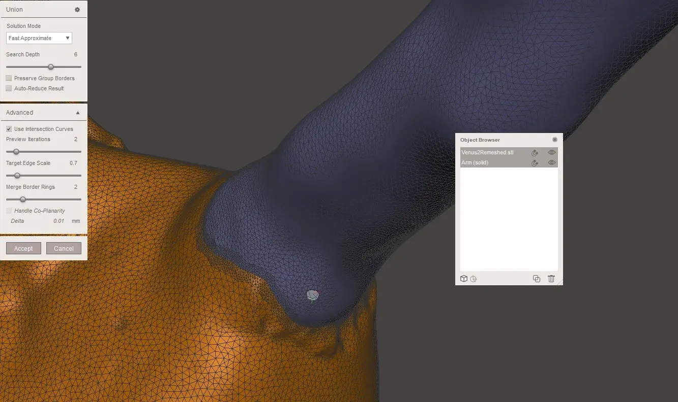
To combine two meshes into one, import both meshes or drag them from the Meshmix library. In the Object Browser, select an object from the main menu and choose Edit → Transform to position each object. With both objects selected, start the appropriate Boolean command, in this case, Union. This is a complex algorithm that merges the two objects into a single shell. In case the object consists of multiple shells, first use the Edit → Separate Shells command. For a Boolean Difference command, the second selected object is subtracted from the first. Because of Meshmixer’s unique version of the Boolean script, it not only works on solid models but also on surfaces.
Precise or Max Quality mode will maintain the intersection curve between both objects, while Fast Approximate is much quicker and usually suffices. If the Boolean operation fails it results in two red colored objects. In that case, turn the Search Depth parameter up to increase the chance of success. Checking Use Intersection Curves also improves quality. Target Edge Scale controls the size of the triangles near the intersection relative to the surrounding ones.
Tip #7: Mesh Repair (STL Repair)
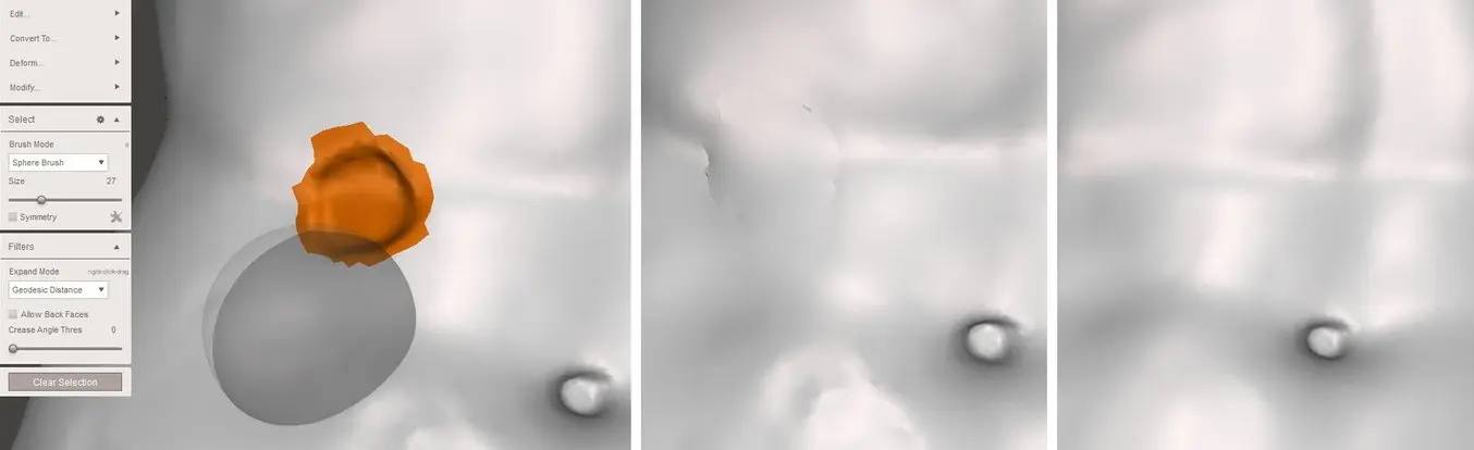
Meshmixer offers several advanced ways of patching up holes in a mesh. Sometimes it is useful to create a hole in order to cut out an irregular area. In that case, enter Select mode and use the lasso to select the area to be removed. Now hit Delete or Edit → Discard (X) to remove all selected faces. Go to Analysis → Inspector and the hole will be detected. Of the available options in the dropdown menu, Minimal Fill results in the least amount of triangles necessary to close the hole. A Flat Fill creates a patch as flat as possible, and a Smooth Fill matches the patch to the curvature of the surrounding area. Auto Repair All usually fixes all holes, as well as intersecting and floating triangles.
An alternative method is to select the area to be deleted and use the Edit → Erase and Fill (F) operation from the popup menu. Setting Type to Smooth MVC results in a good continuous fill. Edit → Make Solid or Edit → Replace and Fill are other methods that will fill all holes. An additional pass with the RobustSmooth sculpting brush will blend the improved area completely into the model.
Tip #8: Adding Thickness
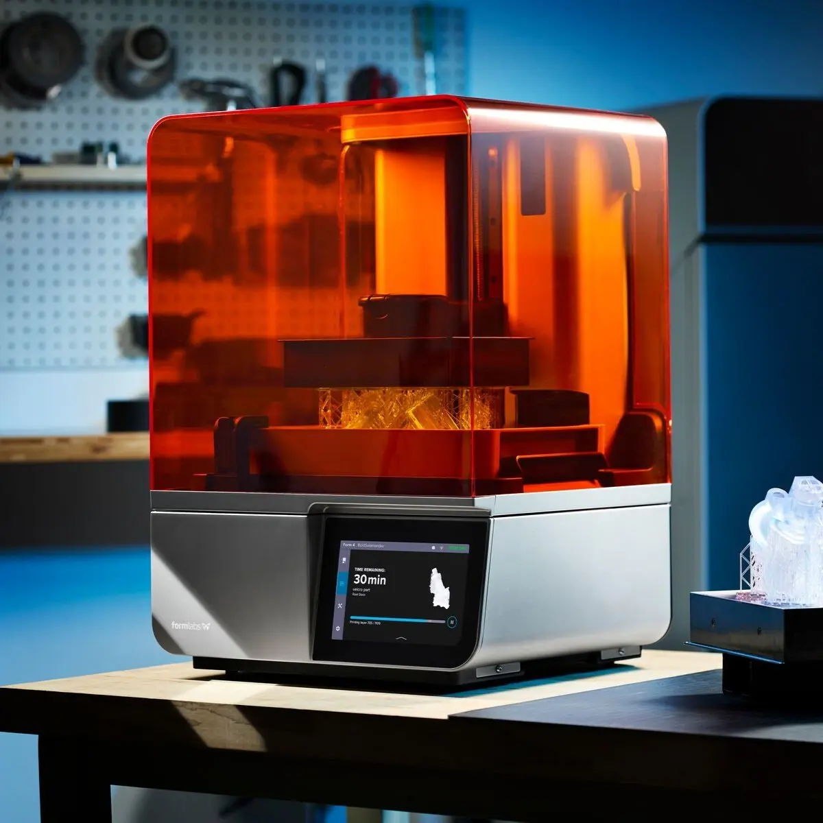
For any feature to be visible after 3D printing, it needs to have a minimum wall thickness or detail size, that’s dependent on the 3D printer and 3D printing technology. Stereolithography 3D printers, like the Form 3, can reproduce some of the finest details.
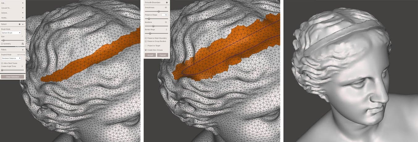
One way to add thickness to a mesh lies in a specific use of the Extrude command. Select the area that needs thickening using Brush mode, which allows selecting (and deselecting by holding Ctrl) individual triangles. It is possible to smooth the selection by choosing Modify → Smooth Boundary from the popup menu. Increasing the Smoothness and Iterations parameters will result in a more clean selection. Now, choose Edit → Extrude (D) with Normal as the Direction setting.
Tip #9: Hollowing Out Parts
At times when you’re not printing functional parts that require a certain strength, adding wall thickness to hollow out your design can be a great way to save a considerable amount of material and time.
To install a wall thickness to the entire model, choose Edit → Hollow. The minimum wall thickness depends on the 3D printing technology. For both SLA and selective laser sintering (SLS), 1 mm is a good minimum offset value.
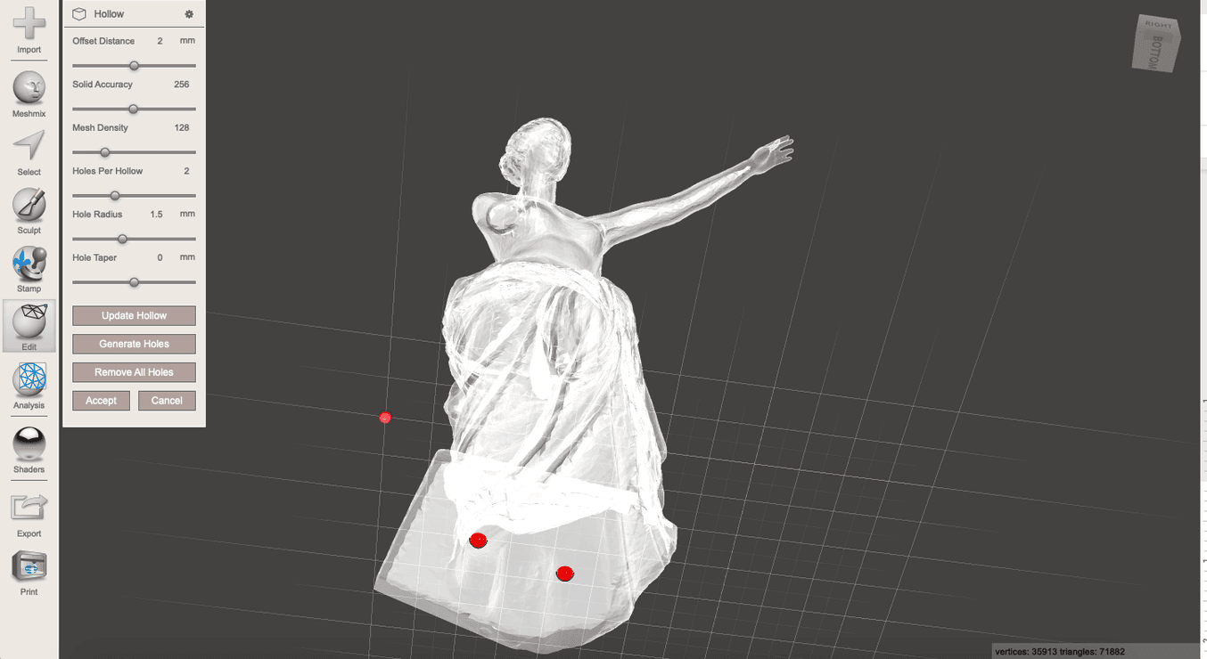
For SLA, include at least two holes with 1.5 mm diameter—one closest as possible to the build platform, the other somewhere on an opposite side. This provides an escape hole for the resin, preventing a pressure differential during the 3D printing process. It also ensures good isopropyl alcohol (IPA) flow during cleaning and air venting afterward.
For SLS models, add two 2 mm holes or one hole with a 4 mm diameter for the entrapped powder to escape. It is possible to Generate Holes automatically or double-click to specify custom locations.
To ensure a watertight model, run Edit → Make Solid after creating holes. This is an intensive operation so make sure the model is now ready for 3D printing.
Using the Analysis → Stability tool we can also conclude that the object volume has been reduced by more than 75% in our example case that’ll significantly reduce material use and printing time.
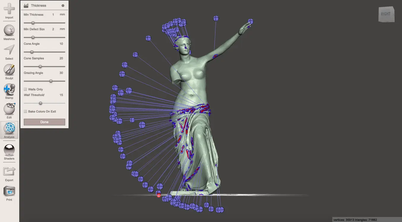
Tip #10: Thickness Analysis
Use Analysis → Thickness to verify if the wall thickness of the model is within acceptable limits for the given 3D printing technology. Not sufficient wall thickness might lead to lost details, or, in a worse case, print failure.
The Minimum Thickness setting checks if the wall thickness meets this dimension, and Minimum Defect Size indicates the minimum size the area needs to have to be marked as below the threshold. Cone Angle, Cone Samples, and Grazing Angle are technical parameters relating to the number of rays calculated from one side to the other and the angle between them in order to determine wall thickness. Lowering the cone samples and setting a higher grazing angle will improve processing times.
Analyzing our single-armed Venus model, there are some areas of low wall thickness, but with SLA 3D printing, only the largest ones on the tunic will need modification, for example using the Inflate brush.
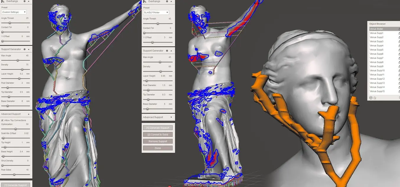
Tip #11: Generating Supports
Not surprisingly, our Venus sculpture was not created with 3D printing design rules in mind more than 2,000 years ago. For successful printing, fused deposition modeling (FDM) and SLA 3D printers will require support structures. Meshmixer offers the possibility to embed support structures directly into the mesh. They are constructed using bifurcating strands that grow up to the overhang, which can save plenty of material compared to raft-based supports.
Advanced print preparation tools like Formlabs’ PreForm software allow you to create and edit optimal support structures with ease for the selected printer and 3D model. For best results, we recommend using PreForm to create support structures. PreForm is free, try it now.
From the main menu, pick Analysis → Overhangs and select a preset pertaining to the 3D printer. Adding a Contact Tolerance specifies the distance from the tip of the support structure to the model in order to facilitate breakaway. Now open the Support Generator that presents us with settings that speak for themselves. Under Advanced Support make sure to check Allow Top Connections for models requiring tall support structures. This will create supports that start somewhere on the model itself rather than starting from the build plate. After tweaking the settings, hit Generate Supports. The support generator is computationally intensive so for large models it is sometimes useful to perform another Edit → Remesh or Edit → Reduce operation to minimize triangle count. It also helps to have the model already positioned with the Z-axis up and snapped to the XY-plane. Use Ctrl + LMB to remove individual supports in areas of high detail where they might interfere with the product geometry, are prone to fail to print, or will be hard to remove post-printing.
With all support structures in place, Convert to Solid combines all connected supports into a single object. The Edit → Separate Shells command then allows saving support structures separately from the model in order to apply different 3D printing settings in the slicer software.
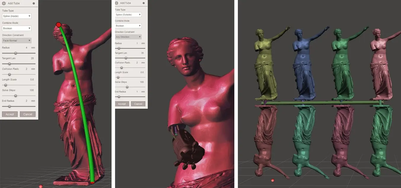
Tip #12: Creating Wires, Tubes, and Channels
Adding wires to a 3D model, for example, for connecting multiple parts in a single print, can take substantial effort if done manually. Delegating this part of the modeling process to MeshMixer will result in a successful model when using the powerful Edit → AddTube tool. This allows the user to specify two points on the mesh surface between which a tube of specified start and end radius gets connected. The Spline type allows curving the tube along the start and the end face normal, with tunable tangent strength. AutoRoute (Smooth) creates a tube that as far as possible passes through the model which is useful for fluid channels or electric wiring routes.
When choosing Boolean in Combine Mode, an outside tube is added to the mesh while an inside tube gets subtracted to create an internal channel. Append creates a new shell inside the same object without merging with it.
In case we want to create an array of miniature objects connected by means of a sprue-type connection, Edit → Transform (T) and Edit → Mirror are useful to scale down and reposition them. With Edit → Align the object can be snapped to the ground plane. Hit Edit → Duplicate and with the new object selected in the object browser, use the Transform tool to move it along the X-axis. Select the two objects and perform a Combine operation to move the models into a single object and create linear patterns rapidly. For more advanced object patterning functions, it’s best to use other software tools, such as Blender’s Array Modifier.
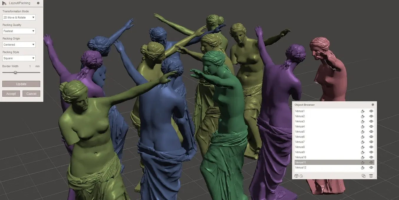
Tip #13: Packing Multiple Objects
When printing multiple objects, it is important to make efficient use of the available space. MeshMixer offers the Analysis → Layout/Packing functionality to layout objects in different ways. It is important to apply the Separate Shells command and correctly orient the objects relative to the ground plane before starting the packing algorithm. For our Venus sculpture, a Square Packing Style proved more efficient than a Circular Packing Style.
Tip #14: Stylistic Variations
Meshmixer also features a list of stylistic variation to allow designers to get creative when editing meshes.
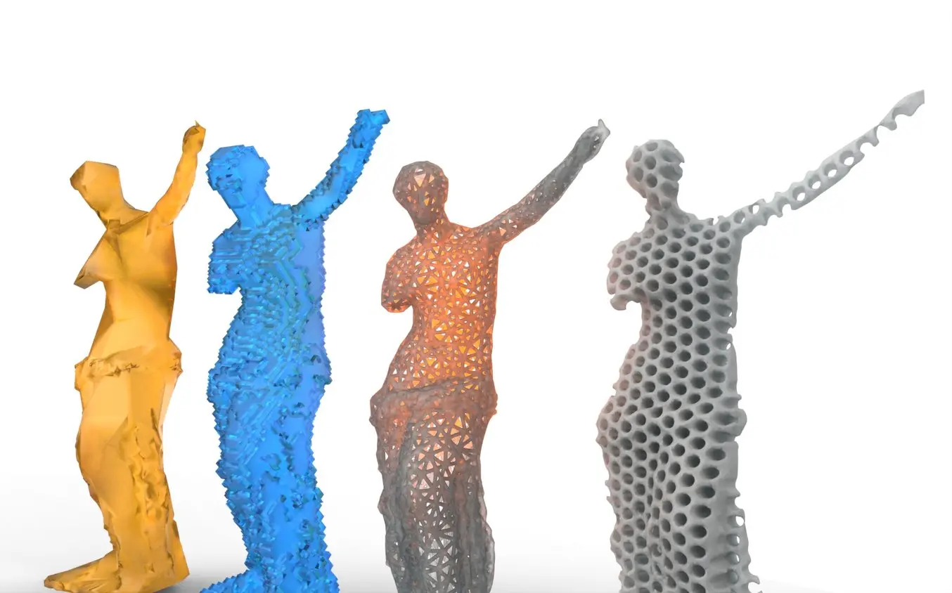
Voxelize
The Edit → Make Solid command from the main menu creates a watertight solid from mesh surfaces by recomputing the object into a voxel representation. If we opt for Blocky mode under Solid Type with large cell size, it results in a funky voxelized model. To prevent straight overhangs that need support structures, the trick is to first rotate the object by 45 degrees over the X or Z-axis using the Edit → Transform tool. Use Edit → Plane Cut to make the bottom flat again.
Low Poly
Making good low polygonal models is an art that often requires many hours of manual design work. MeshMixer provides advanced functionality to turn even complex objects into striking low poly pieces. This can be done in two passes:
-
First, determine the minimum triangle size necessary to preserve detail. This removes unnecessary detail which speeds up experimentation in the second pass. Click Edit → Remesh and choose Relative Density mode. Turn down the Density slider to where the geometry is still reasonably represented, with the Preserve Sharp Edges option left unchecked.
-
Hit Accept and again choose Edit → Remesh. This time, use the Target Edge Length mode to specify the length of the longest edge required in the low poly model under Edge Length. Now check Preserve Sharp Edges and experiment with the Sharp Threshold and Regularity parameters until the model looks like an artistic version of the original one.
First, determine the minimum triangle size necessary to preserve detail. This removes unnecessary detail which speeds up experimentation in the second pass. Click Edit → Remesh and choose Relative Density mode. Turn down the Density slider to where the geometry is still reasonably represented, with the Preserve Sharp Edges option left unchecked.
Hit Accept and again choose Edit → Remesh. This time, use the Target Edge Length mode to specify the length of the longest edge required in the low poly model under Edge Length. Now check Preserve Sharp Edges and experiment with the Sharp Threshold and Regularity parameters until the model looks like an artistic version of the original one.
Wireframe
An open wireframe-style model can be created after first applying the first Remesh pass described in the Low Poly section. Then pick Edit → Make Pattern from the main menu and choose Edges for Pattern Type. This creates a wire at every edge. Choose Dual Edges for a Voronoi-style pattern. Element Dimension represents the wire diameter, which should be at least 2 or 2.5 mm for FDM 3D printing and 1 mm for SLS and SLA 3D printing. Grid Smoothing is an advanced option that will smoothly blend all wireframe components, resulting in a visually and mechanically more attractive design.
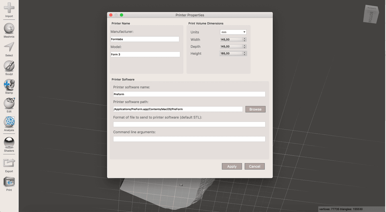
Tip #15: Sending Models to a 3D Printing Software
Using the Print command from the main menu, you can set up printer properties and pick the print preparation tool or slicing program to slice the model and send it directly to the 3D printer.
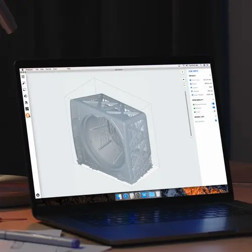
Try Out PreForm (Free)
PreForm is the 3D printing software for Formlabs 3D printers. Get your model ready in minutes, upload to your printer, and let it build.
Get Started With Professional 3D Printing
Looking for the right tool to turn your designs into reality? High-resolution stereolithography (SLA) and selective laser sintering (SLS) 3D printers are fast and cost-effective tools to produce high detail models with a smooth surface finish.
Learn more about 3D printers and see the quality firsthand by requesting a free sample part printed on a Formlabs 3D printer.
Not sure which 3D printing solution fits your business best? Book a 1:1 consultation to compare options, evaluate ROI, try out test prints, and more.