
As a research university in the Helmholtz Association, the Karlsruhe Institute of Technology (KIT) offers space for around 25,000 students for research and development each year. The University of Excellence comprises seven research areas, including energy, environmental, and mobility research.
Doctoral student Lars von Deyn is currently one of the scientists in the field of mechanical and electrical engineering, and he is a research assistant at the Institute of Fluid Mechanics (ISTM). The researchers at the ISTM generally deal with the characterization, physical interpretation, and optimization of natural and technical flow phenomena. In particular, Lars von Deyn would like to contribute to understanding and predicting turbulent flows by generating and analyzing measurement data using a wind tunnel and 3D printed structures.
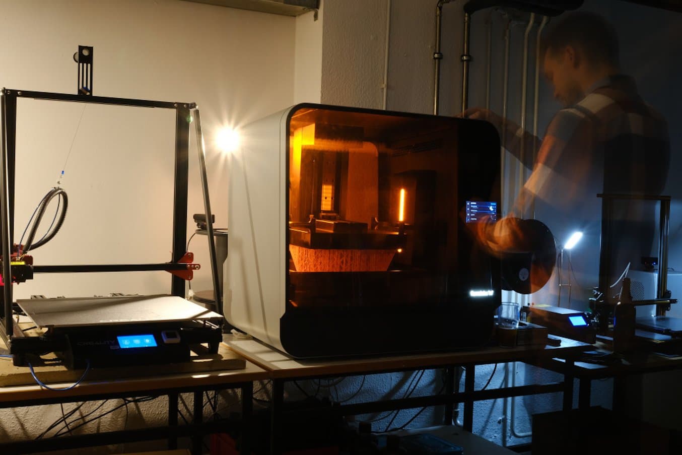
Since such measurements require a high degree of accuracy and reproducibility, the right material is of great importance during manufacturing. For this reason, Lars von Deyn tested the Form 3L stereolithography (SLA) 3D printer and the printed surfaces of the Model V2 and Grey V4 materials for his research and compared them with conventionally CNC-milled surface structures.
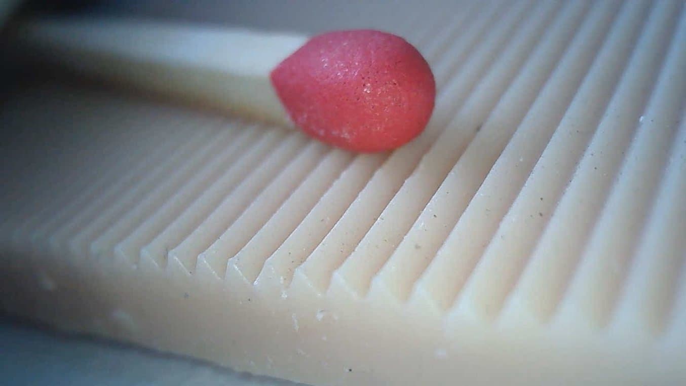
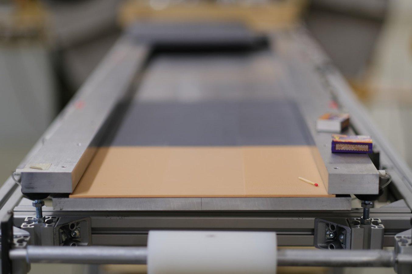
So-called riblets were chosen as the test structure. These in-line longitudinal grooves with a sharp tip are ideal for reducing surface friction in turbulent flows.
Guide to 3D Printing In Education
In this guide, we’ll discuss the benefits of 3D printing in education, from improved student collaboration to workforce development and empowered creativity.
The Project
Wind tunnels are used in a large number of research projects to systematically investigate technical and natural flows. These offer reproducible framework conditions that are easily accessible metrologically. Well-known examples are industrial wind tunnels for studying the aerodynamics of cars and airplanes.
Due to the mostly complex flow conditions—especially in mobility—research objects are often abstracted in order to examine individual aspects in a targeted way. This is also the case in Lars von Deyn's project. Among other things, the doctoral student is focusing on analyzing individual structures for reducing friction in mobility.
Before starting the actual research project, the right manufacturing process and material first had to be found using a test structure. Lars von Deyn chose longitudinal grooves aligned with the main flow, known as riblets. These structures have already been well-researched, so reference values are sufficiently available. In addition, producing the pointed structures is a particular challenge in manufacturing, since sharp corners are usually difficult to manufacture, but are particularly important for the friction-reducing effect of the riblets.
Choosing the Right Manufacturing Method
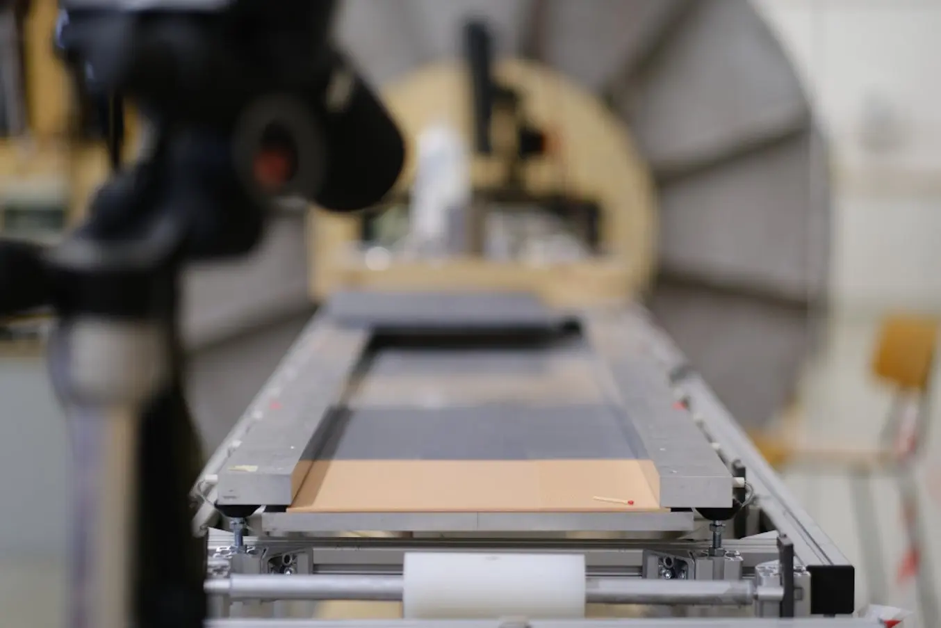
In order to obtain measurement data that can be used for research, an area of 1.5 m x 0.3 m has to be equipped with the structures to be examined in the wind tunnel. Furthermore, the manufacturing method selected has to have consistent accuracy over the entire surface and be able to precisely reproduce the desired surface structure.
Conventional production using a CNC milling machine reaches its limits when it comes to meeting these requirements for installation space and the level of detail in the structures. "I would like to examine structures that are very difficult to produce using machining processes," says Lars von Deyn. The search for suitable manufacturing processes that meet the criteria of the research project led to the choice of SLA 3D printing.
"With SLA 3D printing, you can achieve very good accuracy and depict very fine details. For me, the biggest challenge is producing high-precision structures on a large surface. The Form 3L offers the necessary framework for this."
Lars von Deyn, Scientist, Karlsruhe Institute of Technology (KIT)
He chose the Form 3L because of the build volume and associated number of prints needed. The Form 3L's build volume of 330 mm x 200 mm x 300 mm allows it to print plates measuring 310 mm x 3 mm x 260 mm. With two plates per print, six build are necessary to adequately cover the measuring section.
Choosing the Right Material
In order to guarantee the successful implementation of his research project, Lars von Deyn looked for materials with which details can be reproduced well and at the same time, the smoothest possible surface can be achieved.
Based on these requirements, as well as the characteristics of the Form 3L, the Formlabs support team recommended Lars von Deyn use Formlabs Grey Resin. In addition to a high level of detail, which is necessary for the project, it also requires no post-processing. Model Resin V2 was suggested as the second material, which is also characterized by a high level of detail and a smooth surface.
The two materials were then tested and compared using two riblet test geometries of different sizes and different layer thicknesses.
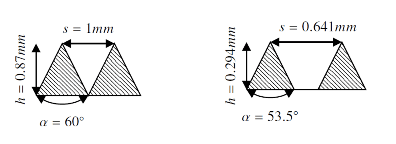
The test structures were printed with different dimensions in terms of apex angle, prominence, and height, and are shown on the left for set1 and on the right for set2.
Analysis
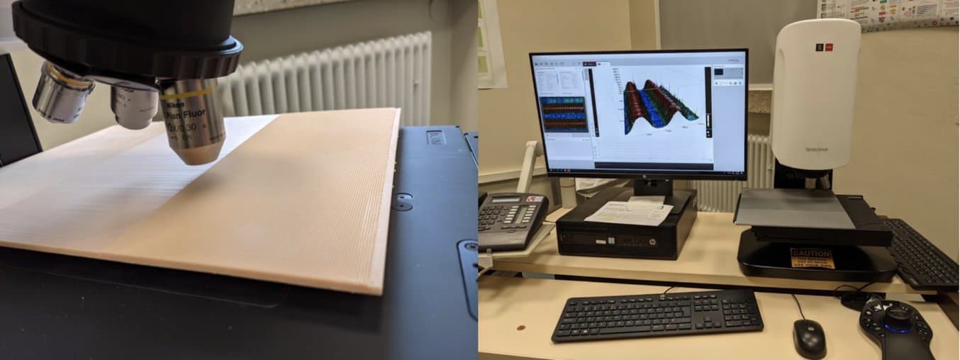
The analysis of the 3D printed results compared to the CNC-milled structures provides information about which material has the best dimensional accuracy and surface quality, and with which printing parameters. A 3D profilometer from the manufacturer Sensofar S neox was used for this.
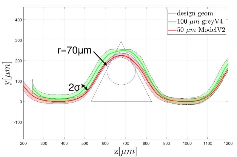
The evaluation with a 3D profilometer excludes the surface accuracy achieved for the 3D printed structures. On the left are the results for Set 1 from the SLA 3D printing process compared to the CNC-milled geometry. The results for the smaller Set 2 can be seen in the picture on the right. The standard deviation is denoted by 𝝈.
The evaluation of the investigations and a comparison of the different materials are listed below.
Set 2
| Grey V4 | Model V2 | Model V2 | |
|---|---|---|---|
| Layer thickness | 100 mu | 25 mu | 50 mu |
| Production method | Form 3L | Form 3 | Form 3L |
| Standard deviation | 8.9 mm | 6.2 mm | |
| Radius | 70 mu | 70 mu | |
| Dimensions | 310 mm x 3 mm x 260 mm | 100 mm x 3 mm x 100 mm | 310 mm x 3 mm x 260 mm |
| Material use | 422 ml | 374 ml | |
| Production time | 2 days, 2 hours | 3 days, 2 hours |
Set 1
| Aluminum | Grey V4 | Grey V4 | Model V2 | |
|---|---|---|---|---|
| Layer thickness | 50 mu | 100 mu | 50 mu | |
| Production method | CNC milling machine | Form 3L | Form 3L | Form 3L |
| Standard deviation | 7.9 mm | 18.6 mm | ||
| Radius | 70 mu | 70 mu | 70 mu | 70 mu |
| Dimensions | 500 mm x 5 mm x 350 mm | 310 mm x 3 mm x 260 mm | 310 mm x 3 mm x 260 mm | 310 mm x 3 mm x 260 mm |
| Material use | 421 ml | 422 ml | 374 ml | |
| Production time | 10 hours machine time | 2 days, 15 hours | 2 days, 2 hours | 3 days, 2 hours |
Evaluation
The experiment shows that layer thicknesses of 100 microns and 50 microns map the desired riblet geometry equally well. The main influence of the layer thickness is reflected in the waviness of the surface, which is quantified by the standard deviation 𝝈. 𝝈 can be determined through the statistical evaluation of the 3D surface scan, as an averaging of the scan in the longitudinal direction of the structure. The standard deviation of Set 1 is about 50 percent smaller for a layer thickness of 50 microns than for a layer thickness of 100 microns. The measured waviness is shown as an enveloping band of color around the mean in the figure above. The chosen interval of 2𝝈 corresponds to a confidence interval of 95 percent. This means that 95 percent of all measured values are within the 2𝝈 interval.
With 3D printing, there is a systematic deviation. The riblet geometry in Set 1 is printed about 30 percent smaller than specified. Subsequent experiments have shown that this systematic error can, however, be easily corrected. The smaller structure in Set 2 is better resolved in terms of riblet height.
As expected, sharp corners cannot be reproduced exactly in SLA printing either. The tip of the triangle is rounded off, resulting in an approximately circular tip with a radius of 70 microns. This tip radius also corresponds to the radius of the CNC-milled geometry. In this regard, a similarly good result is consequently achieved.
Finally, the material Grey V4 with a layer thickness of 50 microns was chosen for the implementation. Since the surface quality was defined as a central requirement of the printing process, the longer printing time compared to 100 micron layers is accepted in order to achieve a less wavy surface. Grey V4 proved to be advantageous due to its ease of use and rapidly progressing software development. It should also be noted that precise dimensional accuracy of precision structures can only be achieved through iterative optimization in combination with surface scans. When handled correctly, excellent printing results can be achieved.