Verbundwerkstoffe wie beispielsweise kohlenstofffaserverstärkte Kunststoffe sind höchst vielseitige und effiziente Materialien, die die Innovation in vielen Branchen vorantreiben, z. B. in der Luft- und Raumfahrt oder im Gesundheitswesen. Dabei übertreffen sie traditionelle Materialien wie Stahl, Aluminium, Holz oder Kunststoff und ermöglichen die Fertigung leichtgewichtiger Hochleistungsprodukte.
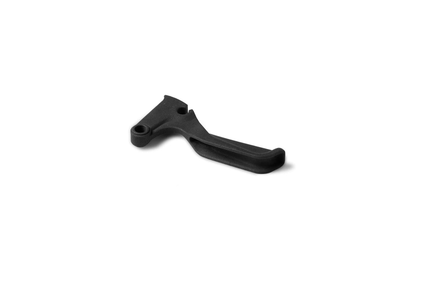
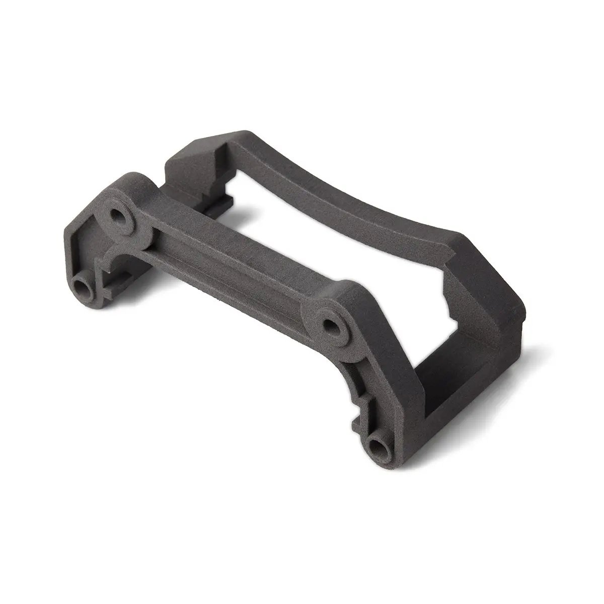
In diesem Leitfaden erlernen Sie die Grundlagen der Herstellung von Kohlenstofffaserteilen, einschließlich mehrerer Methoden zur Schichtung von Kohlenstofffasern, Laminierung und Umformung, sowie Möglichkeiten, mit 3D-Druck die Kosten zu senken und Zeit zu sparen. Es gibt auch direkt 3D-druckbare Verbundwerkstoffe, wie etwa Nylon 11 CF Powder, ein kohlenstofffaserverstärktes Material, das sich perfekt für Anwendungen eignet, die hohe Steifigkeit und Festigkeit erfordern. Nylon 11 CF Powder, gedruckt auf dem Formlabs-Drucker Fuse 1+ 30W, eignet sich für die Herstellung leichter, steifer Teile, die formstabil und wärmebeständig sind und Stößen dauerhaft standhalten.
Kostenlosen Probedruck aus Nylon 11 CF Powder anfordern
Überzeugen Sie sich selbst von der Qualität des carbonfaserverstärkten Nylons. Wir senden Ihnen einen kostenlosen Probedruck an Ihren Arbeitsplatz.
Was sind Verbundwerkstoffmaterialien?
Ein Verbundwerkstoff ist ein Werkstoff aus zwei oder mehr verbundenen Materialien, der andere Werkstoffeigenschaften besitzt als seine einzelnen Komponenten. Dabei verbessern sich üblicherweise die technischen Eigenschaften wie Festigkeit, Effizienz oder Haltbarkeit. Bei Verbundwerkstoffen ist eine Verstärkung in Form von Fasern oder Teilchen in eine andere Komponente eingebettet, die sogenannte Matrix (aus Polymer, Metall oder Keramik).
Faserverstärkte Polymere regieren den Markt und treiben neue Anwendungen in verschiedenen Branchen voran. Kohlenstofffaserverstärkter Kunststoff (auch CFK, Kohlefaser oder Carbon) ist eines davon und kommt als weit verbreiteter Verbundwerkstoff vor allem in Luftfahrzeugen, Rennwagen und Fahrrädern zum Einsatz, da es dreimal stärker und starrer ist als Aluminium und trotzdem 40 % weniger wiegt. Es wird als Verbund verstärkter Kohlenstofffaser mit Epoxidharz geformt.
Die Fasern können eine einheitlich direktionale Webung haben und strategisch ausgerichtet werden, um Festigkeit relativ zu einem spezifischen Vektor zu bieten. Fasern mit Kreuzgeflecht sorgen für Festigkeit gegenüber mehreren Vektoren. Außerdem sind sie verantwortlich für die gesteppte Optik, die man von Verbundwerkstoffteilen kennt. Üblicherweise werden Teile aus einer Kombination beider hergestellt. Es gibt viele verschiedene Arten von Fasern, dazu zählen:
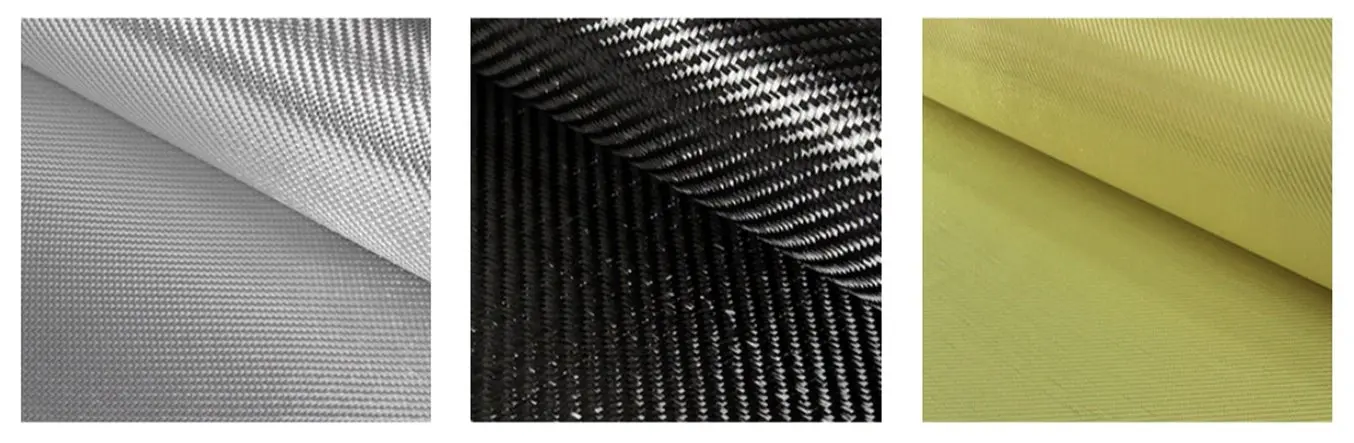
| Glasfaser | Kohlenstofffaser | Aramidfasern (Kevlar) |
|---|---|---|
| Das beliebteste Fasermaterial Leichtgewichtig, moderate Zug- und Druckfestigkeit Kostengünstig und leicht zu verarbeiten | Höchste Festigkeit und bestes Verhältnis von Steifigkeit zu Gewicht (Zug-, Druck- und Biegebruchfestigkeit) Teurer als andere Fasern | Höhere Zähigkeit und mehr Abrasionswiderstand als bei Kohlenstofffaser Geringe Zugfestigkeit Schwer zu schneiden oder maschinell zu bearbeiten |
Harz hält diese Fasern zusammen und bildet einen harten Verbundwerkstoff. Es lassen sich Hunderte Harztypen verwenden. Hier sind einige der beliebtesten:
| Material | Vorteile | Nachteile | Nachhärten |
|---|---|---|---|
| Epoxidharz | Höchste Zugfestigkeit Geringstes Gewicht Längste Haltbarkeit | Höchster Preis Reagiert empfindlich auf Mischungsverhältnis und Temperaturschwankungen | Verwendet einen spezifischen Aushärter (zweiteiliges System) Einige Epoxidharze benötigen Hitze |
| Polyester | Leichte Handhabung (beliebteste Option) UV-beständig Niedrigster Preis | Geringe Festigkeit und Korrosionsbeständigkeit | Benötigt einen Katalysator (Methylethylketonperoxid) |
| Vinylesterharz | Schlägt die Brücke zwischen der Leistung von Epoxidharz und den Kosten von Polyesterharz Beste Korrosions- und Temperaturbeständigkeit sowie Dehnung | Geringere Festigkeit als Epoxidharz und höhere Kosten als Polyesterharz Begrenzte Haltbarkeit | Benötigt einen Katalysator (Methylethylketonperoxid) |
Kostenlose Beratung buchen
Kontaktieren Sie unser Expertenteam für 3D-Druck für eine persönliche Beratung zur passenden Lösung für Ihr Geschäft, eine Analyse Ihrer Kapitalrendite, Testdrucke und vieles mehr.
Drei Methoden zur Produktion von Kohlenstofffaserteilen
Die Fertigung faserverstärkter Polymerteile wie beispielsweise bei Kohlenstofffaser benötigt viel Geschick und Arbeitsaufwand. Sie kommt sowohl bei der Produktion von Einzelstücken als auch von Serien zum Einsatz. Arbeitszyklen reichen von einer Stunde bis zu 150 Stunden, abhängig von der Größe und Komplexität des Teils. Üblicherweise werden bei der Fertigung faserverstärkter Polymere durchgängige, gerade Fasern in der Matrix eingebettet, um einzelne Lagen zu formen. Diese Lagen werden dann Schicht für Schicht auf das fertige Teil laminiert.
Die Eigenschaften des Verbundwerkstoffs stammen ebenso von den Materialien wie vom Laminierungsprozess – die Art und Weise, wie die Fasern eingebettet werden, hat große Auswirkungen auf die Leistung des Teils. Die Duroplast-Harze nehmen zusammen mit der Verstärkung in einem Werkzeug oder einer Form die gewünschte Gestalt an. Durch Aushärtung wird dann daraus ein festes Produkt. Es gibt verschiedene Laminierungstechniken, die sich in drei Haupttypen untergliedern lassen:
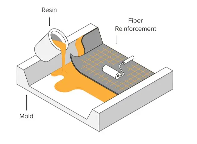
1. Handlaminierung
Bei der Nasslaminierung wird das Fasermaterial in eine Form gelegt. Danach wird mit einem Pinsel, einer Rolle oder einer Sprühpistole das Harz aufgetragen. Diese Methode benötigt das meiste Geschick, um hochqualitative Teile herzustellen. Sie ist jedoch auch die billigste und einstiegsfreundlichste für eigenproduzierte Kohlenstofffaserteile. Falls die Herstellung von Kohlenstofffaserteilen für Sie Neuland ist und Sie noch nicht über die nötige Ausrüstung verfügen, empfehlen wir Ihnen zunächst die Nasslaminierung von Hand.
Dieses kurze Video zeigt den Nasslaminierungsprozess für Kohlenstofffaserteile.
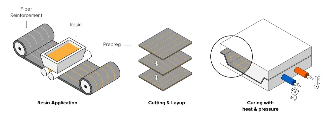
2. Prepreg-Laminierung
Bei der Prepreg-Laminierung werden die Fasern vorher mit Harz angereichert. Die vorimprägnierten Bögen werden kalt gelagert, damit sie nicht aushärten. Die Lagen werden dann unter Hitze und Druck mittels eines Autoklavs in der Form ausgehärtet. Das lässt sich besser konsistent wiederholen und ist präziser, da die Harzmenge kontrollierbar ist. Es ist aber auch die teuerste Technik. Sie kommt für gewöhnlich bei Hochleistungsanwendungen zum Einsatz.
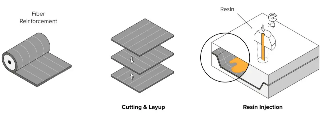
3. Resin Transfer Molding (RTM)
Beim RTM-Verfahren werden die trockenen Fasern in eine zweiteilige Form eingelegt. Die Form wird fest verschlossen und anschließend wird Kunstharz unter hohem Druck in den Hohlraum gespritzt. Der Prozess ist für gewöhnlich automatisiert und wird zur Produktion großer Mengen eingesetzt.
3D-Druck von Formen zur Herstellung von Kohlenstofffaserteilen
Da die Qualität der Form die Qualität des fertigen Teils direkt beeinflusst, ist die Werkzeugbestückung ein entscheidender Aspekt der Fertigung faserverstärkter Polymere. Die meisten Formen bestehen aus Wachs, Schaumstoff, Holz, Kunststoff oder Metall aus CNC- oder Handbearbeitung. Manuelle Techniken sind höchst arbeitsaufwändig und CNC-Bearbeitung durchläuft noch immer einen langwierigen Arbeitsprozess – insbesondere bei schwierigen Geometrien. Außerdem bringt das CNC-Outsourcing hohe Kosten und lange Durchlaufzeiten mit sich. Beide Optionen benötigen geübte Fachkenntnisse und gewähren nur geringe Flexibilität bezüglich Designiterationen und Anpassungen der Form.
Die Lösung dazu ist die additive Fertigung. Sie ermöglicht die schnelle Produktion der Formen und Modelle für die Herstellung von Carbonfaserteilen — und das Ganze bei geringen Kosten. Der Einsatz von Polymer-Werkzeugbestückung im Fertigungsprozess wächst stetig. Dabei ersetzen Sie metallische Werkzeuge durch betriebsintern gedruckte Kunststoffteile. Das ist eine leistungsstarke und kostengünstige Methode, um die Produktionszeiten zu verkürzen und gleichzeitig mehr Designfreiheit zu bekommen. Ingenieure arbeiten bereits mit 3D-Druckteilen aus Polymerharzen bei der Herstellung von Halterungen und Vorrichtungen für Methoden wie Faserwickelverfahren oder die automatisierte Faserpositionierung. Ebenso kommen gedruckte Formen und Formwerkzeuge für Kleinserien im Spritzguss, Thermoformen oder bei der Blechumformung zum Einsatz.
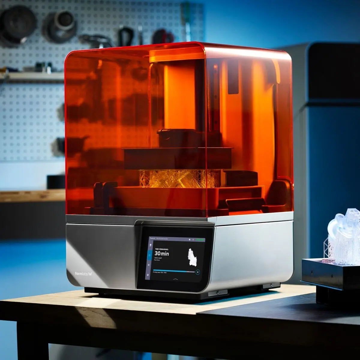
Betriebsinterner Desktop-3D-Druck benötigt nur wenig Ausrüstung und verringert die Komplexität des Arbeitsprozesses. Professionelle Kunstharz-Drucker wie der Form 4 sind erschwinglich, einfach einzurichten und bei steigender Nachfrage gut skalierbar. Die Anfertigung großer Werkzeuge und Formen ist mit großformatigen 3D-Druckern wie dem Form 4L ebenfalls möglich.
Stereolithografie-3D-Druck (SLA) erstellt Teile mit sehr glatter Oberflächenbeschaffenheit, was bei Carbonfaser-Laminierungsformen ausschlaggebend ist. Das ermöglicht komplexe Geometrien mit höchster Präzision. Außerdem bietet die Materialbibliothek von Formlabs technische Kunstharze mit mechanischen und thermischen Eigenschaften, die sich ideal zur Herstellung von Formen und Modellen eignen.
3D-gedruckte Formen verringern die Kosten und die Durchlaufzeit bei der Herstellung von Kohlenstofffaserteilen.
Für kleinformatige Teile können Ingenieure die Form in nur wenigen Stunden kostengünstig direkt drucken. So sparen Sie sich die manuelle Bearbeitung, CNC-Maschinerie, CAM-Software, maschinelle Einrichtung, Einspannung, Werkzeugbestückung oder Spanabfuhr. Arbeit und Durchlaufzeit des Formenbaus sind dabei drastisch verringert. Das wiederum ermöglicht schnelle Designiterationen und individuelle Anpassung der Teile. Dabei können sogar komplexe Formen mit filigranen Details hergestellt werden, die mit herkömmlichen Fertigungsmethoden nur schwer erzielbar wären.
Formenarchitektur und Designleitfäden
Bedenken Sie beim Gestalten einer Form, was sich erfolgreich drucken und formen lässt. Unterschiedliche Formenarchitektur kommt bei verschiedenen Geometrietypen zur Anwendung.
- Einteilige Form mit Vakuumfolie: kommt bei Teilen zum Einsatz, die eine erstklassige Seite mit glänzender Oberfläche benötigen. Dabei kann es sich um die Positiv- oder Negativseite handeln, je nachdem, welche Seite die wichtige ist. Eine Seite berührt die Form, die andere die Vakuumfolie.
- Zweiteilige Form zum Spritzpressen: kommt bei Teilen zum Einsatz, die zwei erstklassige Seiten benötigen. Beide Seiten berühren die Form.
- Aufblasform beim Druckguss: kommt bei komplexen Geometrien zum Einsatz, bei denen Vakuumfolie und Spritzpressen keine Option sind, weil das Teil nicht entformt werden könnte. Eine Seite berührt die Form, die andere die Blase.
- Formmodelle zur Herstellung einer Negativform: kommt zum Einsatz, wenn mehrere Formen benötigt werden, um die Produktion zu erhöhen. Mit einem einzigen Modell lassen sich mehrere Formen erstellen.

Formschrägen hinzufügen: Zwei bis drei Grad Schräge erleichtern den Entformungsschritt und verlängern die Lebensdauer der Form, insbesondere bei starren Formen. Mit einem nachgiebigen 3D-Druckmaterial wie Tough 1500 Resin können Sie aber auch Teile ohne Schräge erstellen und gleichzeitig schwierige Geometrien abbilden, die sich bei einer starren Form nicht entformen lassen würden. Mindestradius: Stellen Sie einen Radius entsprechend der Mindestdicke Ihres Materials ein. So schließen die Fasern bündiger mit den Ecken ab und Sie vermeiden den Einschluss von Luftblasen, was gleichbleibende Qualität bei jedem Teil begünstigt. Vermeiden Sie steile Gefälle und spitze Winkel, da die Arbeit mit flüssigen Geometrien wesentlich leichter ist als mit Ecken und Kanten.
Mindestradius: Stellen Sie einen Radius entsprechend der Mindestdicke Ihres Materials ein. So schließen die Fasern bündiger mit den Ecken ab und Sie vermeiden den Einschluss von Luftblasen, was gleichbleibende Qualität bei jedem Teil begünstigt. Vermeiden Sie steile Gefälle und spitze Winkel, da die Arbeit mit flüssigen Geometrien wesentlich leichter ist als mit Ecken und Kanten.

Verzahnung: Überstände und passende Einbuchtungen helfen bei Formen, bei denen eine präzise Ausrichtung wichtig ist. Einer der großen Vorteile des 3D-Drucks ist, dass er komplexe Geometrien ermöglicht, wie sie bei Designs mit präzisen Ausrichtungen und genauer Positionierung benötigt werden.
Überlauf: Lassen Sie das Material auf einer Erweiterungsfläche überstehen, um hinterher durch Zuschneiden eine präzise Schnittlinie zu erhalten. Mit 3D-Druck drucken Sie solche Flächen ganz ohne Schürze.
Schnittlinien: Dank 3D-Druck können Sie präzise Bearbeitungshilfen direkt eingliedern, z. B. Bohrschablonen, Ritzgräben oder Führungsschienen für Fräsen.
Weitere bewährte Praktiken:
- Drucken Sie mit der kleinstmöglichen Schichthöhe, um die Auflösung und den Entformungsschritt zu optimieren.
- Vermeiden Sie Stützstrukturen auf den Formflächen, um die beste Oberflächenbeschaffenheit zu gewährleisten.
- Verwenden Sie ein Trennmittel. Das ist beim Entformungsprozess unabdingbar.
- Warten Sie nach dem Rühren oder Mischen zwei Minuten, damit etwaige Luft aus dem Harz entweichen kann und nicht miteingeschlossen wird. Gleiches sollten Sie auch nach dem Auftragen der ersten Harzschicht tun. Falls doch kleine Luftblasen zurückbleiben, kann dies während der Nachbearbeitung beim Polieren und Versiegeln ausgebessert werden.
Fallstudie: TU Berlin druckt Carbonfaser-Formwerkzeuge

Die Formula Student ist ein alljährlicher Konstruktionswettbewerb, bei dem Teams von Studierenden aus der ganzen Welt Rennwagen nach Art der Formel 1 bauen und mit ihnen Rennen fahren. Das Formula-Student-Team der TU Berlin (FaSTTUBe) ist eines der größten darunter. 80–90 Studierende entwickeln dort seit 2005 jedes Jahr neue Rennwagen.
Das Formula Student Team der TU Berlin (FasSTTUBe) baut für den jährlichen Wettbewerb Formula Student drei Fahrzeuge.
Da das FasSTTUBe-Team Zugang zu nahezu allen Fertigungstechnologien hat, setzt es den 3D-Druck für drei Zwecke ein:
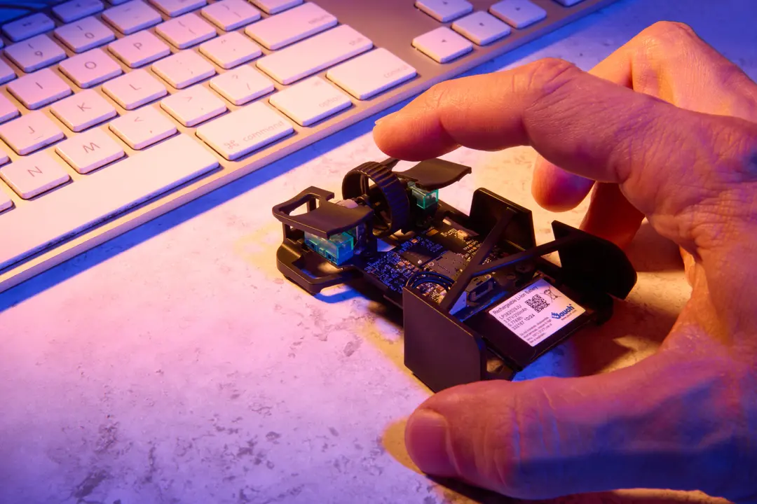
- Prototypen: Die Studierenden druckten Prototypen verschiedener Teile wie z. B. Halterungen der Querstabilisatoren oder der HV-Batterie.
- 3D-gedruckte Formen für Kohlenstofffaserteile: Das Team druckte Dutzende Formen zur Herstellung von Kohlenstofffaserteilen, deren Produktion anders nicht möglich gewesen wäre.
- Endverbrauchsteile: Etwa 30 endgültige Bauteile des endgültigen Fahrzeugs wurden direkt 3D-gedruckt, von Knopfhalterungen über die Schaltung am Lenkrad bis zu Schlauch- und Sensorverbindungen des Kühlsystems.
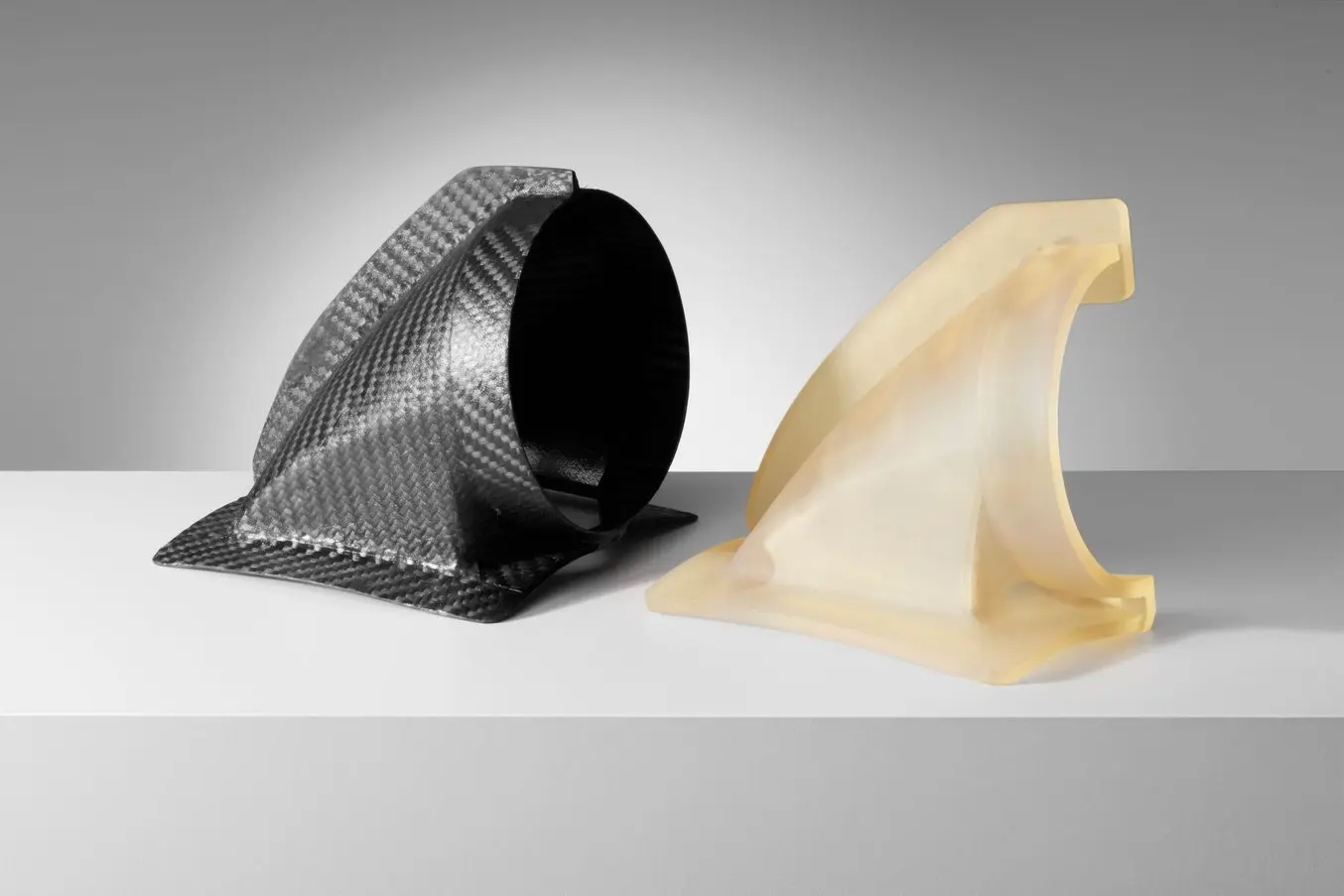
In dieser Fallstudie blicken wir im Detail auf den Formenbau, mit dem das Lenkradgehäuse sowie die Griffe aus Kohlenstofffaser hergestellt wurden.
Gewichtsverringerung ist beim Bau von Rennwagen entscheidend. Um also das Gewicht der Teile zu reduzieren, hätte man ausgehöhlte Lenkradgriffe drucken können, doch sind diese nicht stark genug, um dem festen Griff des Fahrers standzuhalten. Kohlenstofffaser ist ein großartiges Material zur Gewichtsreduzierung, das ebenso stark oder sogar noch stärker ist. Um das Teil dieses Jahr aus Kohlenstofffaser herzustellen, entwickelte Felix Hilken, Team Lead Carbon Fiber and Aerodynamics, einen Arbeitsablauf mit 3D-gedruckten Formen zur Nasslaminierung.
Erforderliche Ausrüstung:
- SLA-3D-Drucker mit Formlabs mit Tough 1500 Resin
- Kohlenstofffaser: drei Schichten zu 200 g, 3 K, 0,3 mm, Köperbindung
- Formentrennmittel: Wachs und Polyvinylalkohol
- Hochfestes Epoxidharz
- Bürste und Schere
- Vakuumfolie, Vakuumpumpe und Entlüftungsstoff
- Schleifpapier

1. Entwurf der Form
Der Griff wurde in zwei Hälften gefertigt, damit sich das Teil entformen ließ. Für jede Hälfte entwarf Felix eine zweiteilige Form mit Elementen, die ohne 3D-Druck nur schwer umzusetzen gewesen wären. Dazu zählen:
- Filigrane Elemente wie enge interne Radien, Gleitflächen oder Flächen mit wechselnden Radien
- Abgerundete spitze Kanten, die nicht aus Aluminiumformen entformt werden konnten
- Vertiefungen für Bohrlöcher, da die präzise Positionierung bei diesem Teil entscheidend ist

2. Druck der Form
Das Team druckte die Formen auf der Form-Serie aus Tough 1500 Resin mit einer Schichthöhe von 50 Mikrometern. Die Druckteile wurden zweimal 10 Minuten lang in IPA gewaschen und 60 Minuten lang bei 70 °C nachgehärtet. Tough 1500 Resin war das Material der Wahl, da es eine gutes Gleichgewicht zwischen Dehnung und Modul bietet. Teile aus diesem Material lassen sich biegen und kehren schnell wieder in ihre ursprüngliche Form zurück. Diese mechanische Eigenschaft ist wichtig, damit die Form bei der Entformung nicht zerbricht.

3.1 Handlaminieren: Trennmittel auftragen
Tragen Sie ein Trennmittel auf, um die Entformung zu erleichtern. Dieser erste Schritt ist äußerst wichtig. Falls nicht die gesamte Fläche eingedeckt wird, lässt sich das Teil nicht von der Form trennen.
- Tragen Sie Wachs auf. (optional, aber empfohlen)
- Tragen Sie Polyvinylalkohol (PVAL) auf.

3.2 Mischen von Harz und Härtemittel
Mischen Sie das Harz mit dem Härtemittel. Das Mischungsverhältnis muss genauestens eingehalten werden. Weicht es auch nur um ein paar Prozent ab, wird das Teil entweder zu weich oder härtet nur teilweise aus. Befolgen Sie die Anweisungen des Harzherstellers sorgsam und lesen Sie vorher das Sicherheitsdatenblatt. Bei dem von Felix verwendeten Harz beginnt die Polymerisierung zwei Stunden nach der Mischung. Also bleiben zwei Stunden für den Laminierungsprozess.

3.3 Auftragen des Harzes
Tragen Sie das Harz mit einem Pinsel auf der Positivseite der Form auf.

3.4 Kohlenstofffaser-Lay-Up
Legen Sie eine Kohlenstofffaserlage auf die Positivseite der Form. Halten Sie sich dabei an die Konturen. Das Team verwendete 3-K-Fasern, um die beste Gewebedicke zum günstigsten Preis zu bekommen. Diese wurden speziell entworfen, um komplexen Konturen zu folgen, und besitzen keine stützenden Stränge.

3.5 Auftragen des Harzes auf die Kohlenstofffaser
Bestreichen Sie die Kohlenstoffaserlage mit Harz und wiederholen Sie die Laminierung. Das Harz verbindet die Lagen und bildet die Matrix des Teils. Außerdem verhindert es, dass die Fasern verrutschen. Felix arbeitete mit drei Lagen Kohlenstofffaser.

3.6 Auftragen des endgültigen Harzes auf das Negativ
Tragen Sie Harz in der Negativform auf und drücken Sie die beiden Hälften der Form zusammen, damit sich keine Luftblasen bilden oder durch die Fasern dringen.

3.7 Entfernen von zusätzlichem Material
Schneiden Sie das überflüssige Material mit einer Schere ab.

3.8 Aushärten
Lassen Sie alles 48 Stunden lang bei Raumtemperatur in Vakuumfolie aushärten. Während der Polymerisierung zieht die Vakuumfolie die Luft heraus und drückt die Lagen gegen die Form, um überschüssiges Harz herauszupressen. Dies stellt das gewünschte Volumenverhältnis von Harz zu Fasern sicher, damit Sie die richtige Steifigkeit des Teils erzielen.

4. Nachbearbeiten und Fertigstellen
Fertigstellung: Schleifen Sie die Kanten ab. Um die Form nach dem Prozess zu reinigen, hat Felix sie ca. 30 Minuten lang in Wasser getaucht, damit sich der PVAL auflöst. Anschließend hat er sie noch mit einer 1500er Körnung geschliffen, um die Harzreste zu entfernen.
Ergebnisse
Durch die Verwendung von Carbonfaser konnte das Team das Gewicht des Lenkradgehäuses von 120 g auf 21 g reduzieren und Designgeometrien umsetzen, die auf herkömmliche Weise nur sehr schwer zu fertigen wären. „Das Tolle am 3D-Druck ist, dass sich komplexe Körper genauso leicht herstellen lassen wie einfache. Der Arbeitsaufwand ist der gleiche und die Ausrüstung ebenfalls“, verrät uns Felix.
Ohne 3D-Druck hätte das Team eine zerspante Aluminiumform in Auftrag geben müssen. Das ist teuer, hat eine lange Durchlaufzeit und benötigt Spezialwerkzeuge. „Würde ich die Form über CNC-Bearbeitung herstellen, müsste ich mir Spezialwerkzeuge beschaffen und darauf warten, dass die Maschine mal frei wird. Und selbst dann hätte ich diese Geometrie nicht hinbekommen. Insbesondere einige der kleinen Ecken. Ich bräuchte ein Design ganz ohne Schrauben, damit die Positionierung des Teils keine Rolle spielt.“
Seiner Einschätzung nach kann man mit einer Form aus Formlabs Tough 1500 Resin etwa zehn Teile anfertigen. Da dies ein manueller Arbeitsprozess ist, hängt alles davon ab, wie sorgfältig die Person arbeitet, z. B. kann die Form bei der Entformung reißen. Andererseits kann man mit mehreren 3D-gedruckten Formen die Produktion steigern. Als alternative Lösung, um die Lebensdauer der Form zu verlängern, könnte man sie durch eine generische Metallform stützen. Dabei trägt eine 3D-gedruckte Einlage die Geometrie und die äußere Metallform hilft, die Gestalt zu erhalten. So etwas könnte man bereits mit einer einfachen Handfräsmaschine herstellen.
| Outsourcing einer CNC-zerspanten Form | Betriebsintern 3D-gedruckte Form | |
|---|---|---|
| Ausrüstung | Kohlenstofffaser, Harz, Werkzeuge, Vakuumfolie | Kohlenstofffaser, Harz, Werkzeuge, Vakuumfolie, 3D-Drucker, Tough 1500 Resin |
| Zeitaufwand für die Formherstellung | 4–6 Wochen | 2 Tage |
| Arbeitskosten | 0 € | 300 € |
| Materialkosten | 0 € | 10 € |
| Gesamtkosten der Formherstellung | 900 € | 310 € |
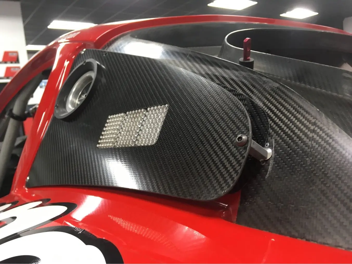
Fallstudie: Automobilbauteile aus Carbonfaser für Panoz
DeltaWing Manufacturing produziert Verbundwerkstoffteile für die Firma Panoz, einen Designer und Hersteller exklusiver, amerikanischer Luxussportwagen. Zur Herstellung von Kohlenstofffaserkomponenten nutzte DeltaWing Manufacturing früher zerspante Modelle, laminierte oder goss eine Form darin und stellte diese fertig, bevor man zur Prepreg-Laminierung des Kohlenstofffaserteils überging.
In den letzten Jahren ging man dann zum betriebsinternen 3D-Druck der Teile über, als Zwischenschritt in diesem Prozess. Panoz benötigte sechs einzelne Lufteinlässe aus Kohlenstofffaser für die Kotflügel eines individualisierten Rennwagens. Um den Arbeitsaufwand und die Durchlaufzeit ihres herkömmlichen Formenbaus zu reduzieren, entschieden sich die Ingenieure bei DeltaWing Manufacturing für den direkten 3D-Druck der Form als Teil ihres Prepreg-Prozesses.
Erforderliche Ausrüstung:
- SLA-3D-Drucker von Formlabs mit High Temp Resin
- Kohlenstofffaser: 4 K, zweidimensionale Webung
- Formentrennmittel: Polyvinylalkohol
- Kaptonklebeband (Polyimid)
- Hochfestes Epoxidharz
- Bürste und Schere
- Vakuumbeutel, Vakuumpumpe

1. Entwurf der Form
Der Lufteinlass wurde aus zwei verschiedenen Teilen mit zwei unterschiedlichen Formen gefertigt, damit die Entformung leichter fällt. Dann wurden die beiden Teile miteinander verbunden. Auch jede der Formen wurde in zwei Teilen gedruckt und dann zusammengesetzt, damit sie im Fertigungsvolumen eines Druckers der Form-Serie Platz fanden. Mit dem größeren Fertigungsvolumen des Form 4L wäre dies jedoch nicht nötig gewesen. Die Teile wurden entsprechend der Formdesignempfehlungen für die additive Fertigung entworfen.

2. Druck der Form
DeltaWing druckte die Form auf einem Formlabs-Drucker mit High Temp Resin und einer Schichthöhe von 100 Mikrometern. Die Wahl fiel auf dieses Kunstharz aufgrund seiner Wärmeformbeständigkeitstemperatur (HDT) von 238 °C bei 0,45 MPa – die höchste aller Formlabs-Kunstharze und eine der höchsten auf dem Markt.
High Temp Resin widersteht hohen Aushärtungstemperaturen, bietet gute Steifigkeit zur Bewahrung der Form während des Vorgangs sowie großartige Detailabbildung, die an das fertige Teil weitergegeben wird. Formlabs empfiehlt, Teile aus High Temp Resin 10 Minuten lang in IPA zu waschen, 120 Minuten lang bei 80 °C nachzuhärten und das Teil dann 3 Stunden lang auf 160 °C zu erhitzen, um eine höhere HDT zu erzielen.

3. Prepreg-Laminierung
DeltaWing Manufacturing nutzte das gewohnte Prepreg-Verfahren zusammen mit der gedruckten Form und einer 4-K-Prepreg-Faser mit bidimensionaler Webung. Jede Form wurde mit Kaptonklebeband bedeckt, um bei jedem Einsatz eine frische Oberfläche zu bieten. Die Fasern wurden in den Formen laminiert. Anschließend wurden die Teile in Vakuumfolie eingeschlossen und in einem Autoklav ausgehärtet, bevor sie schließlich entformt und zugeschnitten wurden. Die gedruckten Formen hielten einer langsamen Aushärtung von 10 Stunden bei 38 °C oder auch einer schnellen Aushärtung von 1 Stunde bei 126 °C stand. Als letzter Schritt wurden die beiden Hälften des Kohlenstofffaserlufteinlasses miteinander verbunden.
Oberflächenbeschaffenheit und Ergebnisse
Das Team testete sechs Iterationen mit einer Form, ohne wesentlichen Verschleiß festzustellen. Wir schätzen, dass ungefähr 10 bis 15 Iterationen mit einer Form möglich sind. Durch die Hitze und den Druck der Autoklaven zur Aushärtung im Prepreg-Prozess hält eine gedruckte Form nur eine begrenzte Anzahl an Iterationen aus. Deshalb wird diese Methode nicht für Großserien empfohlen, eignet sich aber hervorragend für Kleinserien und selbst zur Massenproduktion individualisierter Teile. Das eröffnet eine ganze Bandbreite an Anwendungsbereichen, z. B. Ausrüstung für den Hochleistungssport, maßgefertigte Werkzeugbestückung für die Luft- und Raumfahrt oder patientenspezifische Prothesen im Gesundheitswesen.
3D-Druck mit Kohlenstofffasern
Die Nachfrage nach Arbeitsabläufen, die die Festigkeit, Haltbarkeit und Robustheit traditioneller Carbonfaserteile mit der Agilität, der geometrischen Freiheit und der Reproduzierbarkeit des 3D-Drucks vereinen, ist sehr hoch. Daher überrascht es kaum, dass viele 3D-Druckunternehmen auch 3D-Druck von carbonfaserverstärktem Kunststoff anbieten, wobei die beiden bisher verfügbaren Prozesse entweder zerkleinerte oder durchgängige Fasern einsetzen.
Das mit Carbon-Kurzfasern angereicherte Nylon 11 CF Powder für den industriellen SLS-3D-Ducker (selektives Lasersintern) Fuse 1+ 30W produziert starke, leichte und hitzebeständige Teile, ohne auf herkömmliche Methoden wie Überzug oder Zerspanung angewiesen zu sein.
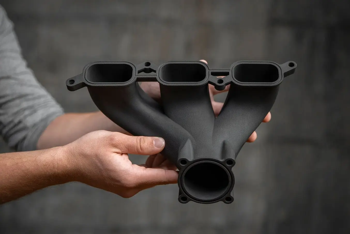
Nylon 11 CF Powder von Formlabs ist stark, leicht und hitzebeständig und damit ideal geeignet für Anwendungen in der Automobilindustrie, Luft- und Raumfahrt und der Fertigung.
Kostenlosen Probedruck anfordern
Sehen und fühlen Sie die Qualität von Formlabs aus erster Hand. Wir senden Ihnen einen kostenlosen Probedruck an Ihren Arbeitsplatz.
Steigen Sie in die Kohlenstofffaser-Fertigung ein
Die Fertigung faserverstärkter Polymere ist ein aufregender, aber auch schwieriger und arbeitsaufwändiger Prozess. Mit 3D-gedruckten Formen und Modellen für Carbonfaserteile verringern Unternehmen die Komplexität dieses Arbeitsablaufs, gewinnen mehr Flexibilität und Gestaltungsfreiheit und reduzieren die Kosten sowie die Durchlaufzeit.
Für direkt 3D-gedruckte Teile mit den Eigenschaften von Kohlenstofffaser und den zusätzlichen Vorteilen der geometrischen Flexibilität und eines einfacheren und effizienteren Prozesses stehen Materialien wie Nylon 11 CF Powder von Formlabs für die SLS-Drucker der Fuse-Serie zur Verfügung.
Wenden Sie sich an unser Team, um Ihre Anwendung zu besprechen und herauszufinden, wie Sie den 3D-Druck am besten zur Produktion von Carbonfaserteilen einsetzen können.