
Snap-fit joints are so common in everyday products that many people may not even know that the features they’re constantly using are classified as snap-fit joints. This type of design feature is found in consumer products and industrial applications all around us — everything from food container lids, to seat-belts, and door latches — snap-fit joints are everywhere we look.
As 3D printing has become more powerful and accessible, more people are now able to design their own functional prototypes or end-use parts, and need to learn how to create a high-quality, functional snap-fit joint. In the following guide, we’ll go through what defines a snap-fit joint, when and how they’re most useful, the design guidelines for a successful snap-fit, and the types of 3D printing technologies and materials for the best performance.
To see the step-by-step walkthrough for designing and 3D printing a snap-fit enclosure, watch our on-demand webinar here.
Book a Free Consultation
Get in touch with our 3D printing experts for a 1:1 consultation to find the right solution for your business, receive ROI analyses, test prints, and more.
Introduction to Snap-Fit Joints in 3D Printing
What Is a Snap-Fit Joint?
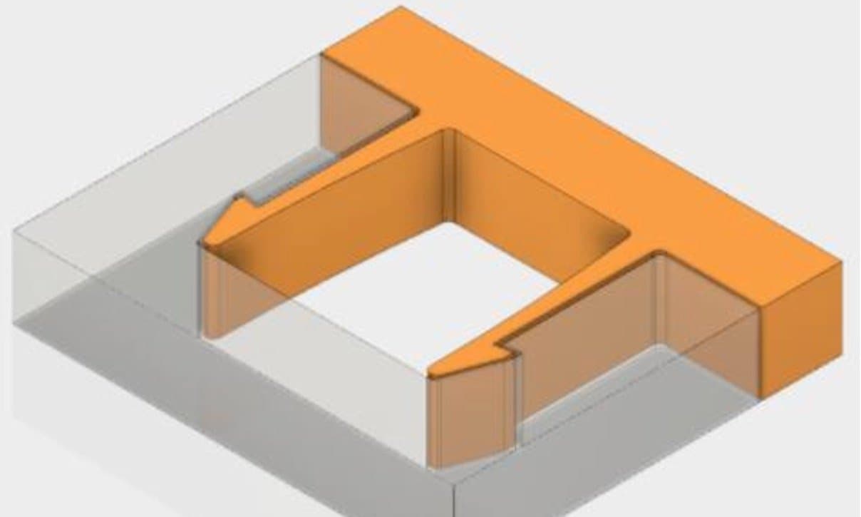
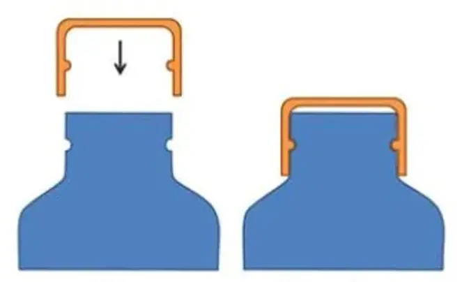
The red part is the protruding component, also known as the male, hook, bead, or head, which needs to be stressed slightly at its base to allow it to catch and snag on the green negative part, or undercut.
A snap-fit joint is common, economical, and easy way of joining two parts or components together. Though there are different types of snap-fit joints, they all share in common that they have a protruding feature on one component that snags and ‘catches’ on a depressed or negative feature (called the undercut) on the other component. The protruding feature can also be called the hook, bead, or head. Some snap-fit joints are inseparable once joined together and some are able to separate and rejoin multiple times, depending on the shape of the undercut and the amount of force required to deform the protrusion to ‘de-snag’ it from the undercut.
Snap-fit joints are easy ways to create assemblies, because, especially for plastics, they require only a slight force on the joint’s protruding part, and can typically be disassembled easily.
Types of Snap-Fit Joints and Applications
Before beginning to design a snap-fit joint, first decide which type of snap-fit joint to use: there are four common snap-fit joint types.
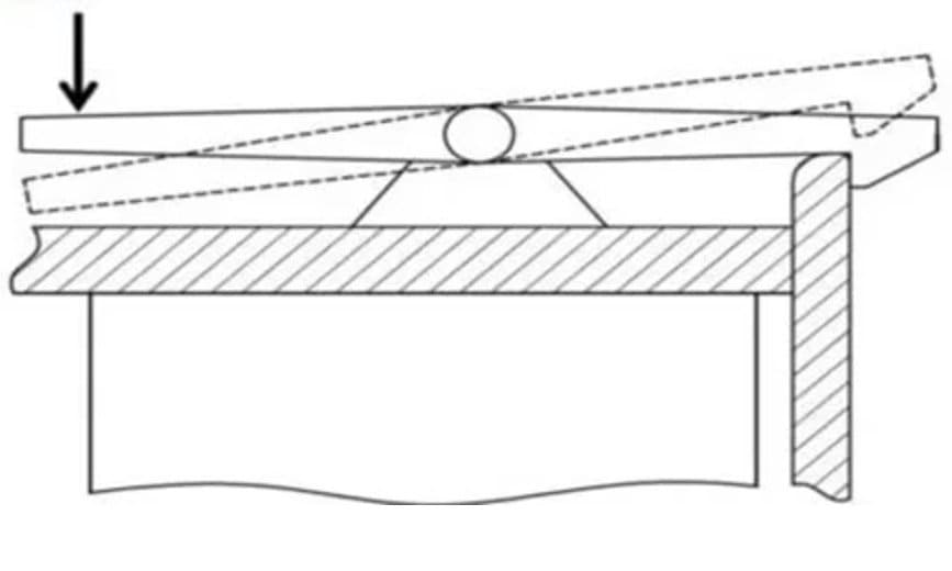
Cantilever Snap-Fit Joints
- Cantilever arm with interlocking feature at the free end
- Cantilever arm deforms through the cavity, snapping into place at the end, and returning to a non-stressed shape
- Most commonly found snap-fit joint
- Example: Seat or backpack buckles
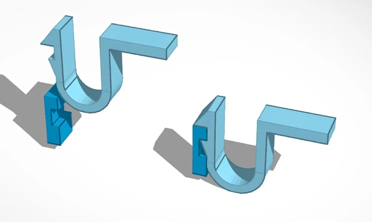
U-Shaped Snap-Fit Joints
- Similar to a cantilever snap joint, if the arm was bent back onto itself
- Example: Electronics enclosures
Torsion Snap-Fit Joints
- Similar to cantilever snap-fits, but cantilever arm is held in place through a torsional force, like a spring or lever
- Example: Lock-able stroller or cart wheels
Annular Snap-Fit Joints
- Almost always for cylindrical or circular shapes
- A slightly more flexible ring is compressed onto a more rigid ring component with a ridge that snags and holds the flexible component, holding it tight through tension
- Example: Bottle caps
For a detailed exploration into snap-fit joints and how to design them for 3D printing, download MIT's design guide.
3D Printing Snap-Fit Joints
Plastics are very well suited for snap-fit joints because of their high flexibility, and therefore 3D printing polymers excel in creating these types of simple assemblies. Rapid fabrication of these plastic snap-fit joints is simple enough once you understand basic design guidelines and printing parameters.
The most common 3D printing methods have their own strengths and weaknesses, especially in relation to snap-fit joints, which require tight tolerances and mechanical strength.
Request a Free Sample Part
See and feel Formlabs quality firsthand. We’ll ship a free SLA sample part to your office.
How to 3D Print Snap-Fit Joints
Choosing a 3D Printing Process for Snap-Fit Joints
The three most common plastics 3D printing processes, namely, fused deposition modeling (FDM), stereolithography (SLA), and selective laser sintering (SLS) 3D printers can all produce working snap-fit joints for easy, 3D printed assemblies. But when considering which technology and material to choose for your specific application, it’s important to note the differences between these methods.
Tolerancing is very important, as is surface finish, because the two components of the snap-fit joint need to fit closely together, while allowing room for movement into place. SLA printers typically produce parts with the best surface finish, but in the case of snap-fit joints, the slightly grainy surface of SLS parts may actually aid in the security of the snap-fit joint.
Suitability of common 3D printing processes for 3D printing snap-fit joints:
-
FDM: Fair, depending on orientation (orient parts for strength in the XY plane, not Z). FDM parts typically exhibit slightly worse tolerances than either SLA or SLS, as well as more prominent layer lines that can interfere with the fit of the snap-fit joint.
-
SLA: Good, tight tolerances and fast print speeds enable rapid, highly accurate iteration. SLA 3D printers also enable a range of materials and mechanical properties, making it easy to optimize for strength, rigidity, or flexibility, depending on the goals of the snap-fit joint (e.g. whether you want it to be detachable or permanent).
-
SLS: Excellent, end-use material properties make rugged snap-fit joints durable and long-lasting. The slightly grainy surface of the SLS 3D printed parts can make a snap-fit joint even stronger, as the added friction holds it in place more securely. Additionally, SLS materials are industry-standard thermoplastics, like nylon, nylon composites, and TPU. With the mechanical properties already familiar and pre-determined, you can use SLS to make snap-fit joints as part of larger assemblies, with predictable and reliable reactions to stressors.
The following is a summary of the major factors to consider when choosing between FDM, SLA, and SLS 3D printers.
| Fused Deposition Modeling (FDM) | Stereolithography (SLA) | Selective Laser Sintering (SLS) | |
|---|---|---|---|
| Resolution | ★★☆☆☆ | ★★★★★ | ★★★★☆ |
| Accuracy | ★★★★☆ | ★★★★★ | ★★★★★ |
| Surface Finish | ★★☆☆☆ | ★★★★★ | ★★★★☆ |
| Throughput | ★★★☆☆ | ★★★★☆ | ★★★★★ |
| Complex Designs | ★★★☆☆ | ★★★★☆ | ★★★★★ |
| Ease of Use | ★★★★★ | ★★★★★ | ★★★★☆ |
| Pros | Low-cost consumer machines and materials Fast and easy for simple, small parts | Great value High accuracy Smooth surface finish Fast printing speeds Range of functional applications | Strong functional parts Design freedom No need for support structures |
| Cons | Low accuracy Low details Limited design freedom | Some materials are sensitive to long exposure to UV light | Slightly rough surface finish Limited material options |
| Applications | Concept modeling Rapid prototyping Functional prototyping Manufacturing aids | Concept modeling Rapid prototyping Functional prototyping Rapid tooling Manufacturing aids Low volume, bridge, or custom manufacturing Dental models and appliances Medical models and medical devices Jewelry prototyping and casting Models and props | Rapid prototyping Functional prototyping Low volume, bridge, or custom manufacturing Long-lasting, durable manufacturing aids Medical devices, prosthetics, and orthotics |
| Print Volume | Up to 300 x 300 x 600 mm (desktop and benchtop 3D printers) | Up to 353 x 196 x 350 mm (desktop and benchtop 3D printers) | Up to 165 x 165 x 300 mm (benchtop industrial 3D printers) |
| Materials | Standard thermoplastics, such as ABS, PLA, and their various blends. | Varieties of resin (thermosetting plastics). Standard, engineering (ABS-like, PP-like, flexible, heat-resistant, rigid glass-filled), castable, and dental and medical (biocompatible). Pure silicone and ceramic. | Engineering thermoplastics. Nylon 12, nylon 11, glass or carbon-filled nylon composites, polypropylene, TPU (elastomer). |
| Training | Minor training on build setup, machine operation, and finishing; moderate training on maintenance. | Plug and play. Minor training on build setup, maintenance, machine operation, and finishing. | Moderate training on build setup, maintenance, machine operation, and finishing. |
| Facility Requirements | Air-conditioned environment or preferably custom ventilation for desktop machines. | Desktop and benchtop machines are suitable for an office environment. | Workshop environment with moderate space requirements for benchtop systems. |
| Ancillary Equipment | Support removal system for machines with soluble supports (optionally automated), finishing tools. | Washing station and post-curing station (both can be automated), finishing tools. | Post-processing stations for powder management and part cleaning. |
| Equipment Costs | Budget FDM printers and 3D printer kits start at around $200. Professional desktop FDM printers range from $2,000 to $8,000, and industrial systems are available from $15,000. | Low-cost resin 3D printers are available for $200 to $1000, professional SLA 3D printers are in the $2,500 to $10,000 range, and large-format resin 3D printers are in the $5,000 to $25,000 range. | Benchtop industrial SLS 3D printers start just under $30,000 for the printer and $60,000 for the entire ecosystem, including powder management and cleaning stations. Traditional industrial SLS printers start at around $200,000. |
| Material Costs | $50-$150/kg for most standard filaments, and $100-$200/kg for support materials or engineering filaments. | $100-$200/L for most standard and engineering resins, $200-$500/L for biocompatible materials. | $100/kg for nylon. SLS requires no support structures, and unfused powder can be reused, which lowers material costs. |
| Labor Needs | Manual support removal (can be mostly automated for industrial systems with soluble supports). Lengthy post-processing is required for a high-quality finish. | Washing and post-curing (both can be mostly automated). Simple post-processing to remove support marks. | Simple and semi-automated workflow for cleaning parts and recovering powder. |
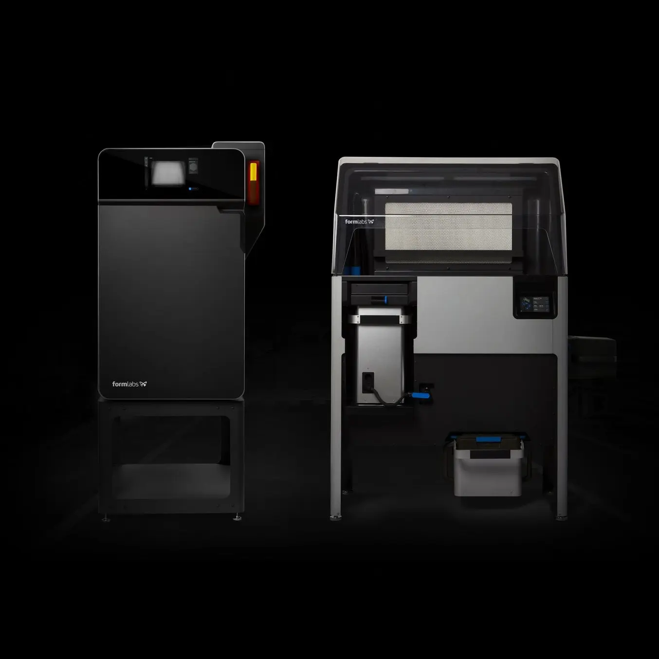
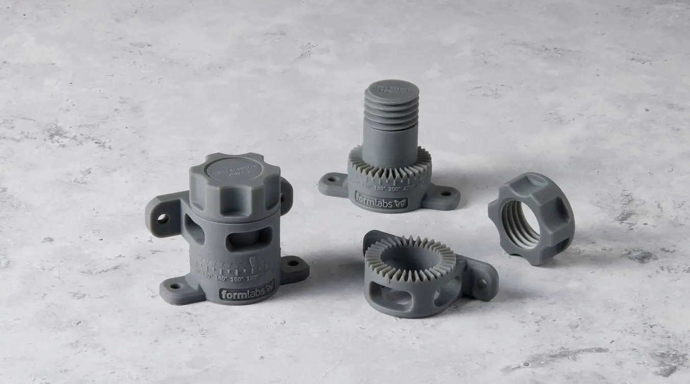
Formlabs’ Form Series SLA 3D printers and Fuse Series SLS 3D printers can produce snap-fit joints in a range of materials, quite rapidly and affordably. Their speed and low cost per part enable you to rapidly test and iterate your snap-fit joint designs as well, so that you can optimize the strength and performance of your snap-fit assembly.
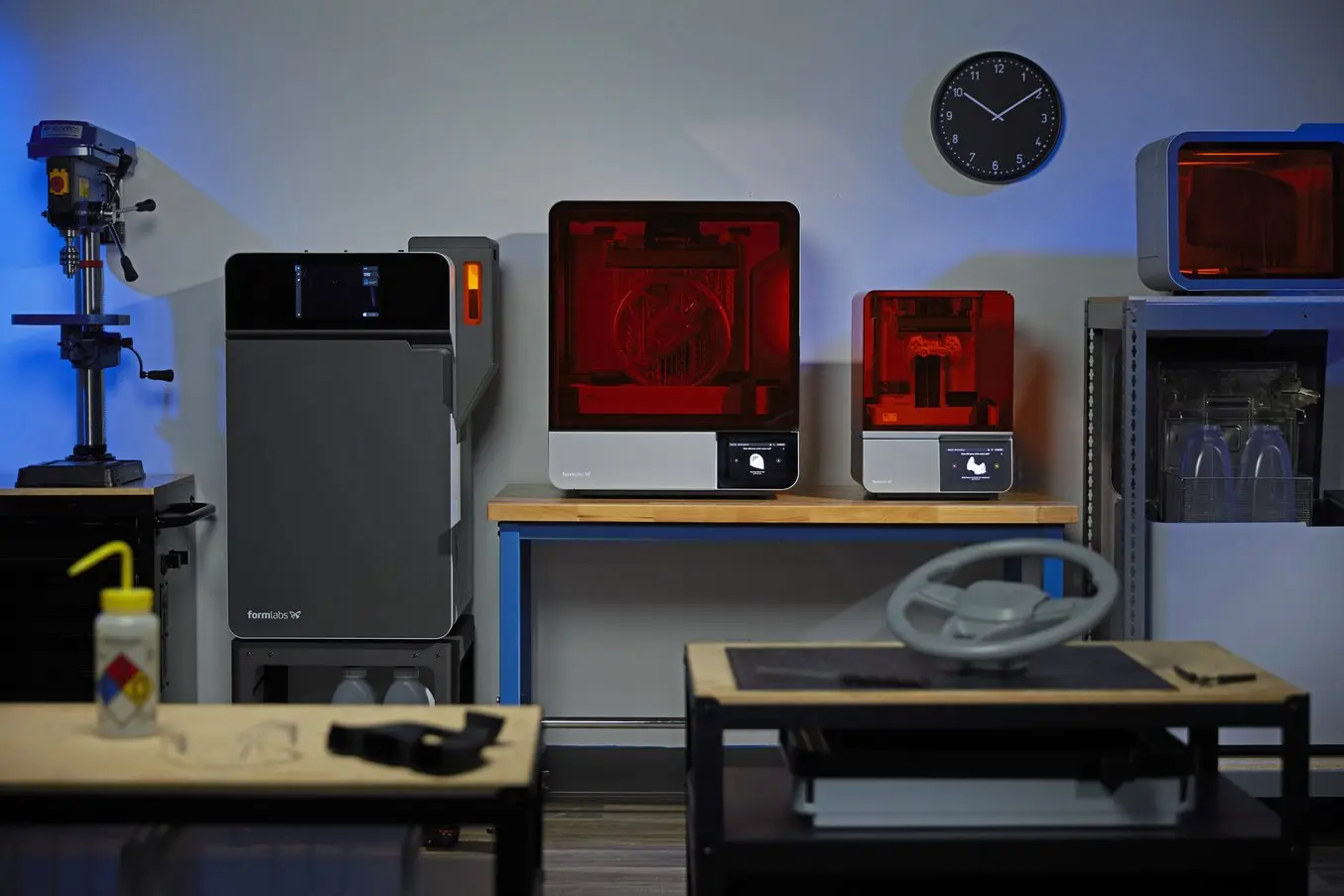
From left to right: Formlabs' Fuse 1+ 30W SLS 3D printer, Form 4L large-format SLA 3D printer, Form 4 desktop SLA 3D printer, and Form Cure L (top) and Form Wash L (bottom) SLA post-processing solutions.
Introduction to 3D Printing With Desktop Stereolithography (SLA)
Looking for a 3D printer to produce high resolution models fast? Download our white paper to learn how SLA printing works and why it's the most popular 3D printing process for creating parts with incredible detail, high dimensional accuracy, and superior surface finish.
Introduction to Selective Laser Sintering (SLS) 3D Printing
Looking for a 3D printer to create strong, functional parts? Download our white paper to learn how SLS printing works and why it's a popular 3D printing process for functional prototyping and end-use production.
Materials for 3D Printing Snap-Fit Joints
When designing a snap fit joint, either the material has already been chosen (with a pre-set acceptable strain) and you must alter the dimensions of your snap-fit design to accommodate this strain, or, your dimensions are set, and you must choose a material that will perform as necessary with those dimensions.
When choosing a material, first choose your 3D printing technology: FDM, SLA, or SLS. For FDM 3D printed parts, strength varies by axis; if the cantilever can only be created in the Z axis (with the stress being applied along the layer lines) elongation at break is reduced by about 50% and tensile strength by about 20-30%. SLA 3D printed parts are isotropic, so the cantilever can be printed in any orientation. SLS 3D printed parts are anisotropic, but with only a small degree of variation between the XY and Z axes, with the exception of carbon fiber filled powders like Nylon 11 CF Powder, which has its greatest strength in the X axis (following the direction carbon fibers are laid out by the powder recoater).
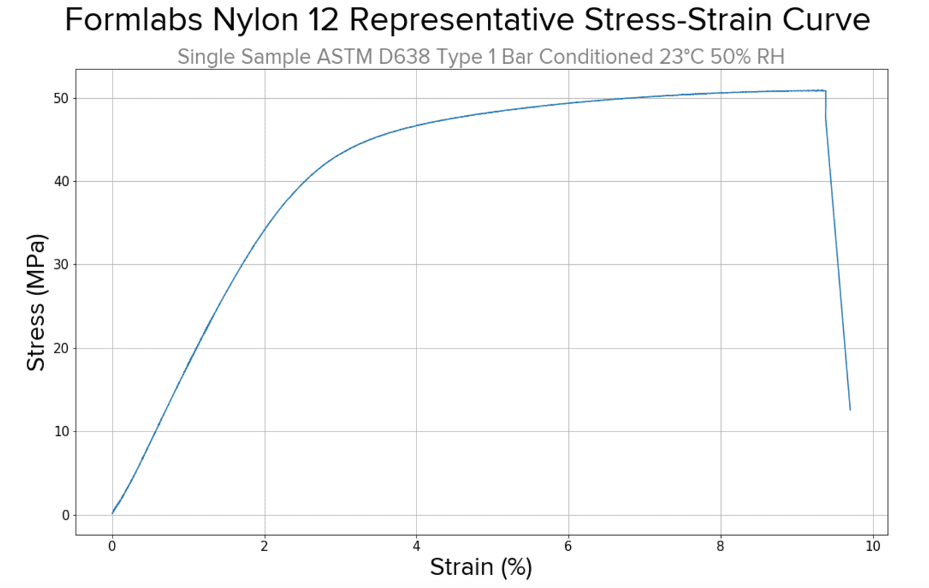
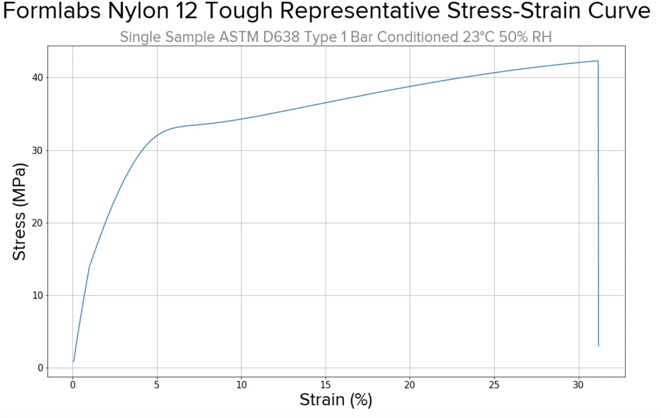
Acceptable strain can be determined by looking at the stress/strain plots for different materials. With a lower acceptable strain, dimensions like cantilever length and root width need to be altered accordingly. With a higher acceptable strain, you could make a longer cantilever or a thinner base, while still creating a functional snap-fit joint. Consider the following stress strain plots, recognizing that these tests are done on ASTM Type I bars, not snap-fit joints. Proper design considerations can overcome weaknesses or lower acceptable strains in a material, though these plots are excellent resources if you’re limited in your dimensional variation and are simply looking for the most functional material.
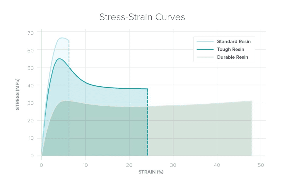
For SLA resins, consider this chart comparing three types of resins: standard (mostly used for prototyping), and ‘tough’ and ‘durable’ resins (used for more functional or higher cycle volume assemblies).
Optimizing Design for Functional 3D Printed Assemblies
Designing for proper tolerance and fit lowers post-processing time and ease of assembly, and reduces the material cost of iteration. Download our white paper to learn more about tolerance and fit in 3D printing designing functional 3D printed assemblies.
Best Practices for Designing Snap Fits for 3D Printing
There are no exact dimensions that are ‘correct’ for any snap-fit joint — the optimal width, length, and shape of the different components of your snap-fit joint will change based on material type and overall size. However, there are some basic guidelines engineers follow when designing snap-fit joints, especially for 3D printing.
- A longer hook reduces stress on the base.
- A lower height reduces stress and the force necessary to assemble and disassemble the snap-fit joint.
- Width of the root does not effect tolerance of stress on the overall structure.
- Taper your hook, or create a ‘trapezoidal’ elongated hook, rather than a straight/parallel/rectangular hook.
- Optimize for curves at the edges of your hook rather than fillets.
- There is no perfect clearance for any assembly — some applications may require more force than others to remove the hook from the undercut, as a good thing, some may be designed specifically to disassemble easily.
- When in doubt, test and iterate!
Step-By-Step: Designing and 3D Printing a Custom Raspberry Pi Case
Step 1: Prepare the Custom Design
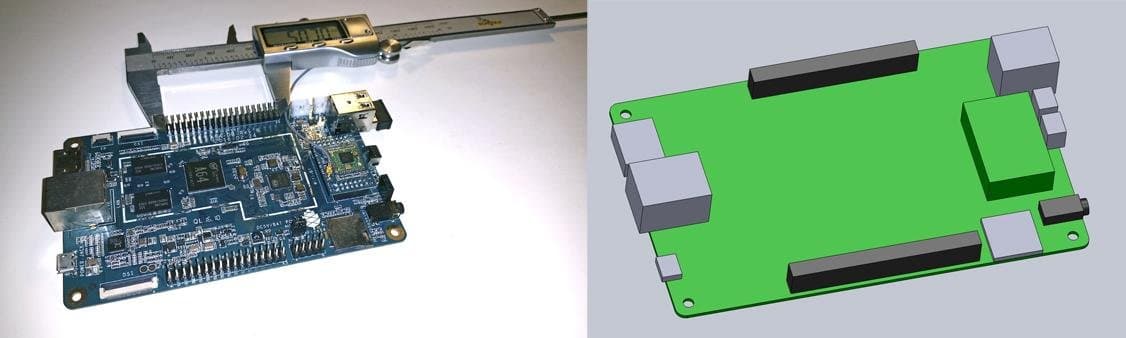
Measure your electronic component (left). Begin your 3D model with basic boxes (right).
For this project, we’re going to make a case for a Pine 64, a single board computer (download the .STL file on Pinshape to follow along). This tutorial uses Solidworks because of its popularity in product design and engineering, but you can use a similar CAD software.
First, use digital calipers or a ruler to measure your electronic component. We like to start enclosure designs by accurately reverse-engineering the PCB, measuring the board size, the location of mounting holes, and any ports or plugs that will need to be accessed through the enclosure. You might want to simply measure the overall maximum dimensions as a box, but it’s essential to know exactly where the main features are so that you can accommodate them. In Solidworks, reproduce these measurements as a grouping of basic boxes in a single part file.
Step 2: Ensure Features Are Printable and Oriented Optimally for Chosen 3D Printing Technology
When printing snap-fit parts like this case with SLA 3D printers, you have more than enough dimensional tolerancing to create the small holes and features the design requires. If you’re unsure about your part, consult the design guide, like this Form 4 Design Guide for Formlabs’ SLA 3D printer and this Fuse Series Design Guide for the Formlabs Fuse Series.
Print orientation affects not only part quality and printability, but it can also affect mechanical properties, post-processing time on support removal, and print time. SLA snap-fit joint components should be oriented at a slight angle to the build platform to lessen the peel forces that might cause print deformation or lower accuracy. SLS snap-fit joint components are self supported, but for certain materials, like Nylon 11 CF Powder, should be oriented so the direction of strain is parallel to the top of the build chamber, so that the carbon fibers are rolled in that direction and overall strength is maximized.
Step 3: Designing the Bottom of the Snap-Fit Enclosure
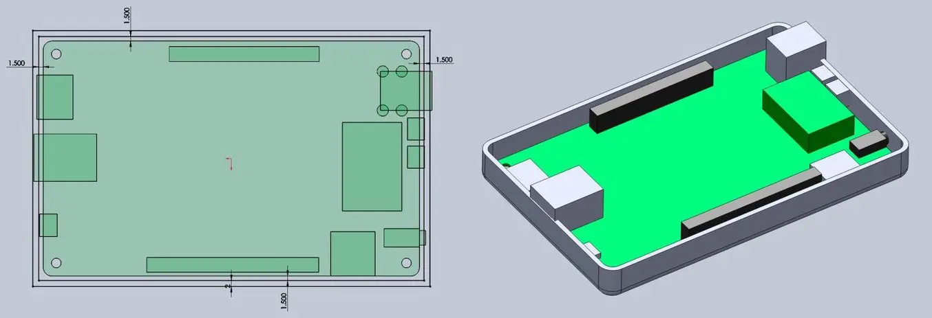
Add space between the perimeter of your electronic component and the enclosure (left). Build the walls of the bottom enclosure in your 3D model (right).
Design your snap-fit joint enclosure as an assembly, with each half of the enclosure modeled as a separate part. Consider the following:
-
How much of a tolerance to have between the perimeter of the PCB and the enclosure. Both Formlabs SLA and SLS 3D printers can easily achieve a 0.4 mm tolerance, while FDM 3D printed parts may warp slightly, and a more conservative tolerance closer to 1.5 mm to 2.0 mm may be best.
-
Cut away port openings — considering the spatial need for cable material around the port opening as well as the port itself. An extra 2.0 mm all the way around the port opening is a good starting point.
-
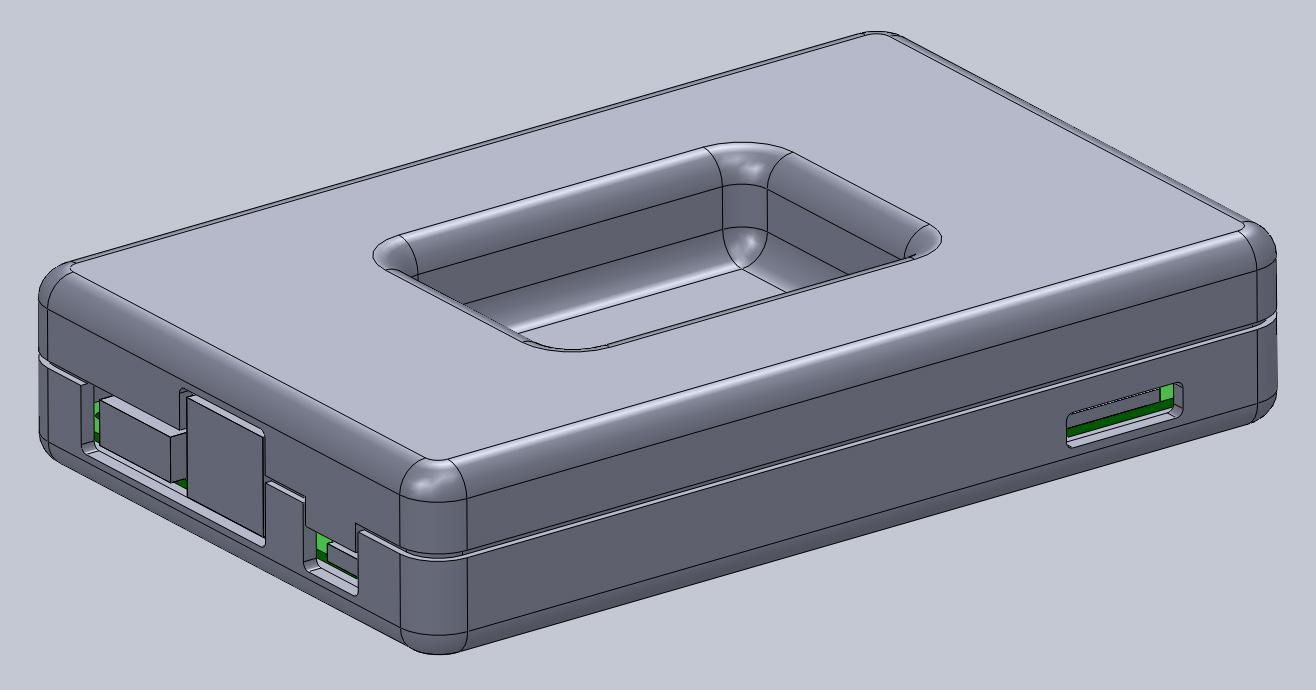
Choose whether to create a larger bottom half of the enclosure where all ports fit inside, or one like the above image, where some ports stick up a bit. Here we’ve made a shallower bottom half so that the cables only have to reach a short ways inside, and rely on the top half to cover the rest of the protuding ports.
Add extruded cuts and cutouts to the bottom enclosure to fit ports.
Step 4: Designing the Top of the Snap-Fit Enclosure
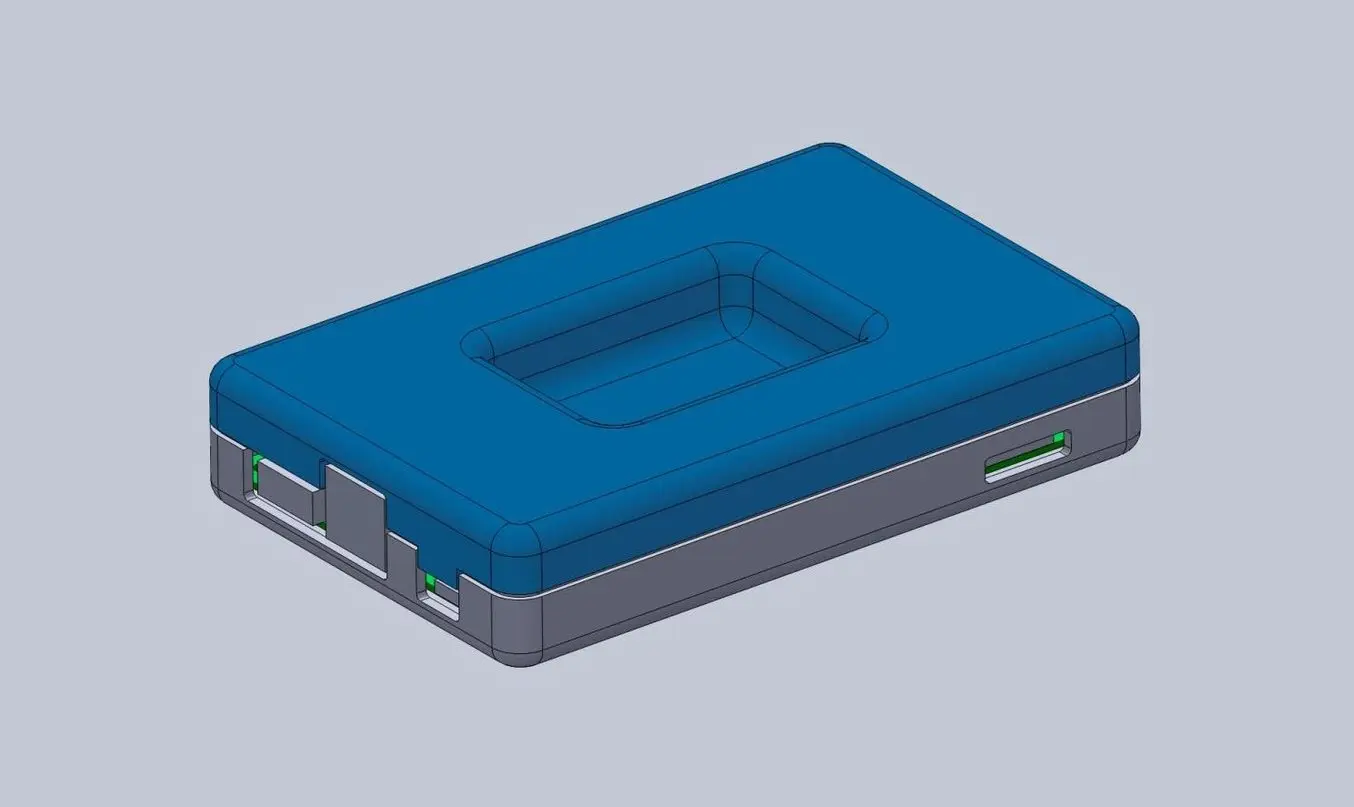
The top half of the snap-fit enclosure is a near mirror image of the bottom half.
The top enclosure has the same treatment of the cut details to accommodate the taller ports and additional material to close off gaps in the bottom enclosure. The sunken portion in the middle is optional, but adds a slightly more organic and interesting visual detail.
Step 5: Designing the Snap-Fit Joint
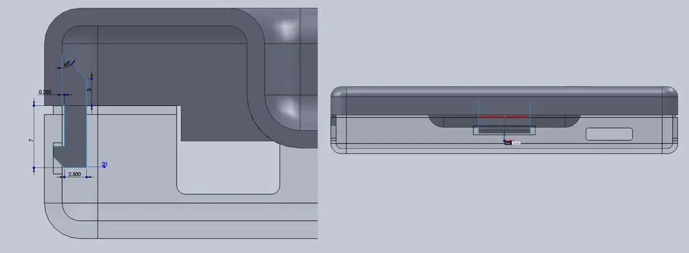
With a basic internal cantilever snap, you can lengthen the amount of plastic engaging into the snap for a stronger lock.
You could use any of the types of snap-fit joints we talked about earlier, but here we opted for the most basic — and internal cantilever snap-fit joint that offers strength with minimal material usage. The snap-fit design is the same on both sides of the enclosure. To enhance the strength of the snap-fit joint, you can extend the protrusion so that it requires more force to remove it from the cavity.
In this snap-fit assembly, it’s only 1.2 mm, but 2 mm or more would make the snap-fit enclosure much more tightly secured — there is no right answer, it just depends on your ideal use-case and how easily you’d like to diassemble the enclosure.
In this particular design, the pins on the PCB take up quite a bit of room, so the snap-fit ‘lock’ is able to just squeeze in, while still providing enough force to hold the enclosure together. The cantilever joint is extruded 20 mm long, which increases strength.
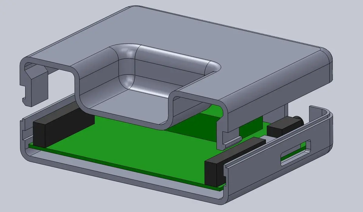
This sectioned exploded view shows the snap details on each side.
Above you can see a sectioned exploded view of the snap details on the enclosure, along with the PCB showing the location of the pins (in black), which limit the size of the cantilever joint. Alternatively, instead of the snap cavity hiding inside of the bottom enclosure, you could cut this detail through to the outside, allowing your snap-fit joints to be longer.
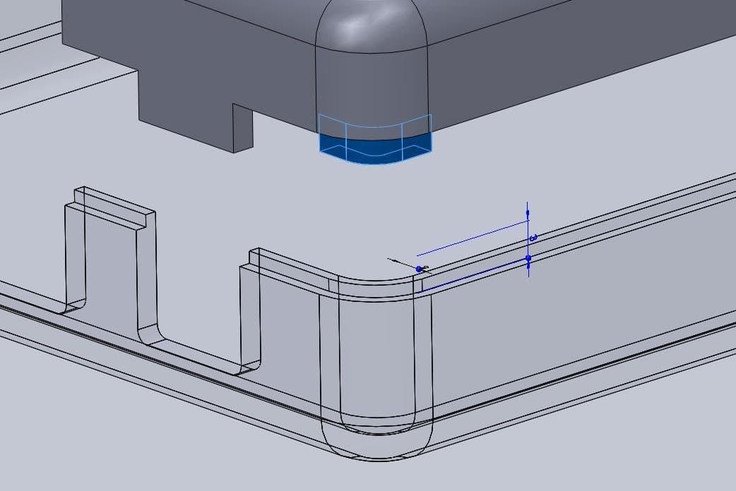
Lugs are small extrusions that slide within the opposite enclosure to secure the two halves.
Add lugs — small extrusions that insert into the opposite enclosure — to your design to keep the two halves from sliding. Because we created two snap-fit joints on opposite sides, you might need these on just the two blank sides. For this larger case, we put them in each corner. The material extrudes only 3 mm down, but this is enough to prevent movement on 3D printed interlocking parts.
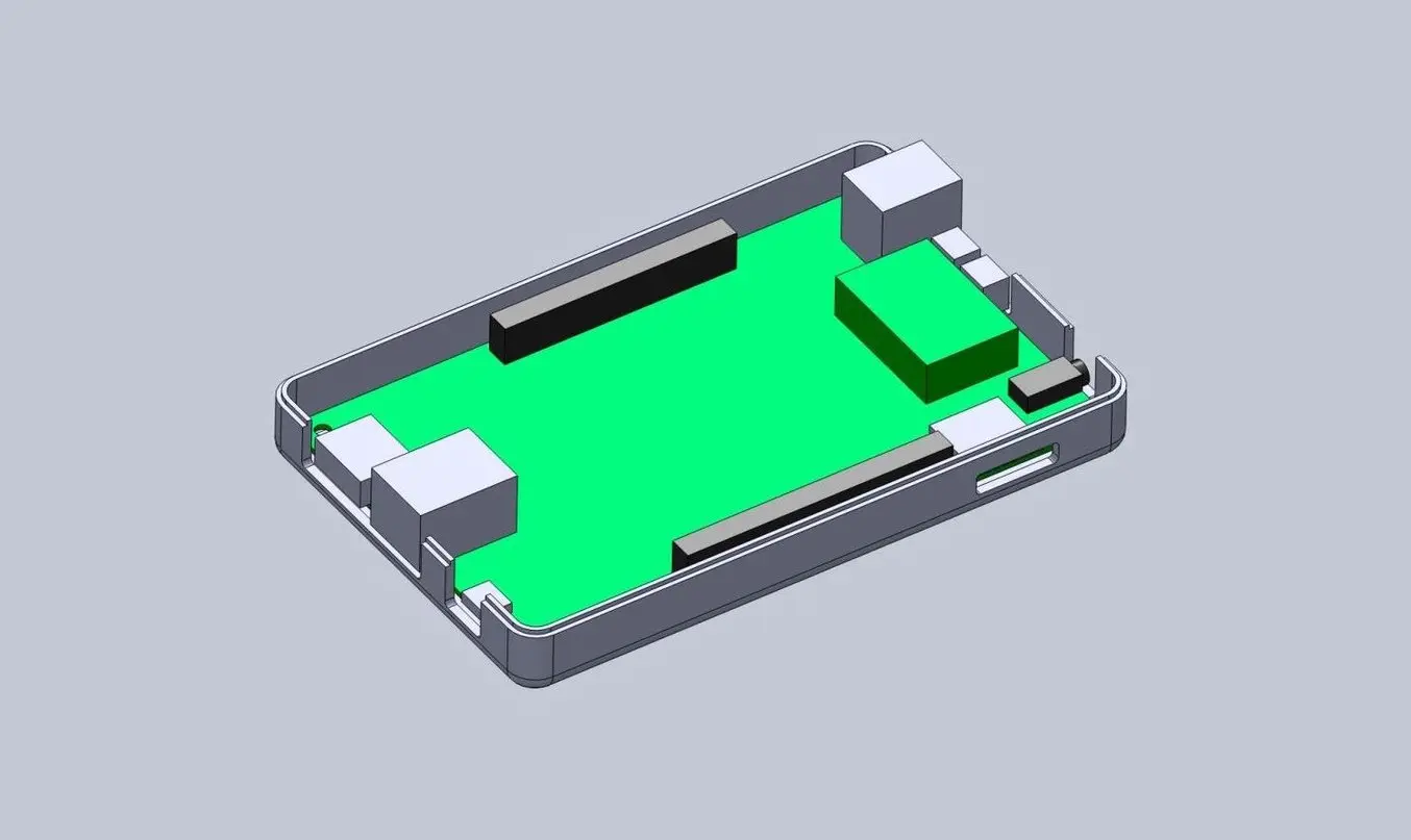
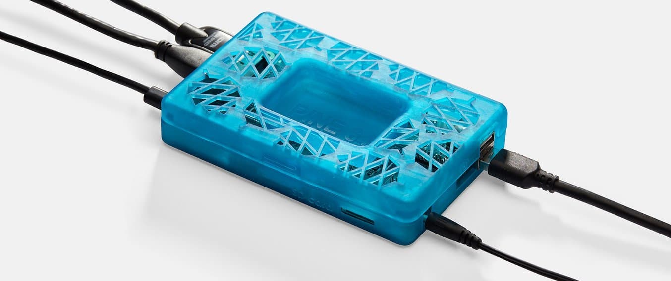
This basic snap fit enclosure can be adapted for nearly any small electronic component.
Step 6: Add Final Details To Your Enclosure
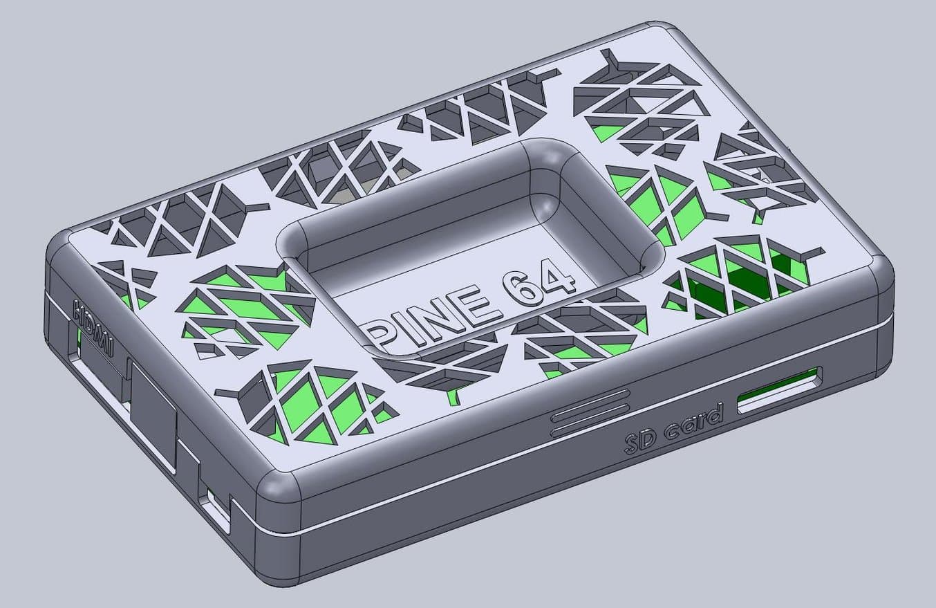
The final design includes unique features along with the snap fit enclosure, ready to be 3D printed.
Though adding extra details beyond the functionality of the snap-fit joint aren’t necessary, they can elevate your design without too much added effort. Once your part is finalized in your 3D design software, export it to PreForm, and choose your printing technology and material.
PreForm, Formlabs’ print preparation software for both SLA and SLS technologies, has many features built in, like adding texturing, extruding product names or labeling for iterative efforts, and more. Once you’re set up your print (either manually or using PreForm’s automated print preparation tools like auto-generated supports for SLA or auto-generated packing for SLS), you can add additional details, or make edits to the orientation and support structures.

Step 7: 3D Print and Post-Process Your Snap-Fit Joint Enclosure
Once your part is ready to be printed, send it to the Form Series or Fuse Series printers through PreForm. When the print is done, post-process it by removing supports and washing and curing the parts (SLA) or removing powder, media blasting and polishing (SLS). Additional, advanced post-processing techniques like coating, plating, vapor smoothing, and dyeing are possible, and can make your parts look more like end-use consumer products. Certain processes, like coating, may affect tolerances and the function of snap-fit joints, so consider these in your original designs.
3D Printing Snap-Fit Joints for Enclosures and More
3D printing offers a range of benefits for the fabrication of snap-fit joint parts like enclosures, boxes, lids, and functional assemblies. The ability of advanced 3D printers and materials to create complex, organic shapes that have tight tolerances, fine features, and smooth surface finishes make it an ideal technology for fabricating these parts. 3D printed materials have become more industrial and durable, making long-term use of snap-fit joints possible, even with repeated usage.
To learn more about the different 3D printing materials available, visit our materials library or request a sample.
Not sure which 3D printing solution fits your business best? Book a 1:1 consultation to compare options, evaluate ROI, try out test prints, and more.