
Tip:
Refer to our Fuse Series SLS Design Guide [EN] [DE] [ES] [FR] [IT] [JA] [RU] [ZH] for more information.

A successful 3D print starts with a well-designed model. Follow our best practices to optimize designs and reduce failures.
Note:
The guidelines below were developed using Formlabs Nylon 12 on the Fuse 1. You may experience slight variations with other Formlabs materials or different settings.
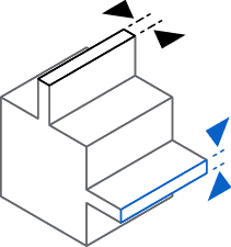
Minimum unsupported wall thickness
Vertical walls: 0.6 mm/600 microns
Horizontal walls: 0.3 mm/300 microns
An unsupported wall is one that is connected to other walls on fewer than two sides. An unsupported vertical wall with a thickness of 0.6 mm or less or an unsupported horizontal wall with a thickness of 0.3 mm or less may warp or detach from the model during printing. Thinner walls have reduced strength.
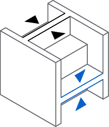
Minimum supported wall thickness
Vertical walls: 0.6 mm/600 microns
Horizontal walls: 0.3 mm/300 microns
A supported wall is one that is connected to other walls on two or more sides. A supported vertical wall with a thickness of 0.6 mm or less or a supported horizontal wall with a thickness of 0.3 mm or less may warp or detach from the model during printing. Thinner walls have reduced strength.
Minimum pin/wire wire diameter
Recommended: 0.8 mm/800 micron diamater
A pin or wire is a feature whose length is at least two times greater than its width. Pins or wires with a diameter less than 0.8 mm may deform or break during the print.

Note: Cleaning small wires
Take extra care when separating printed parts with thin wires from the powder cake, as they can easily be damaged. Filleting the edges where they meet the bulk of the part mitigates this risk.
Minimum assembly tolerance
Features less than 20 mm2: 0.2 mm/200 microns
Features greater than 20 mm2: 0.4 mm/400 microns
Clearance is the distance between two parts of a model (e.g., the distance between a pair of gears). Leave a slight clearance between printed parts intended to mesh or interface after printing, like assembly joints or gears.

Integrated assembly clearance
Features less than 20 mm2: 0.3 mm/300 microns
Features greater than 20 mm2: 0.6 mm/600 microns
Clearance is the distance between two parts of a model (e.g., the distance between a pair of gears). For parts that are printed together in an integrated assembly, leave clearance to prevent the parts from fusing together during the print.

Separate part clearance
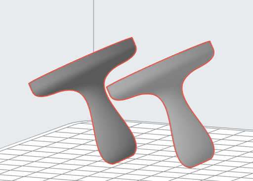
Clearance is the distance between two parts of a model. Parts that are intended to be separate and not interact with one another should be placed at least 5 mm apart to minimize thermal warping effects from the neighboring part.
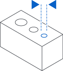
Minimum hole diameter
Recommended: 1.0 mm/1,000 microns
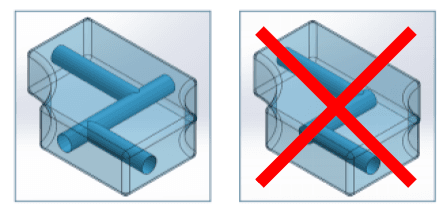
Holes with a diameter of less than 1.0 mm in the X-, Y-, and Z-axes may close during printing. The accuracy of a hole not only depends on the diameter of the hole, but also on the thickness of the wall through which the hole is printed. The thicker the wall section, the less accurate the hole becomes. Through holes must also allow for line-of-sight clearance to ensure all material is cleared during post-processing.
Tip:
For precisely concentric holes, design an undersized pilot hole and use a reamer to open the hole to its intended diameter.
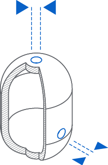
Minimum drain hole diameter
Recommended: 3.5 mm/3,500 microns
Enclosed cavities remain filled with unsintered powder without proper drain holes. For best results, include at least two drain holes when designing a cavity, each greater than or equal to 3.5 mm in diameter.
Tip:
More and larger drain holes make it easier to remove unsintered powder from internal cavities. To guarantee a clean internal surface, design the part so that the surface in question is easy to access with cleaning tools.
Minimum embossed detail
A. Horizontal faces:
A.1 Depth: 0.15 mm/150 microns
A.2 Width: 0.35 mm/350 microns
A.3 Text font height: 4.5 mm/4,500 microns
A.4 Text font depth: 0.3 mm/300 microns
B. Vertical faces:
B.1 Depth: 0.35 mm/350 microns
B.2 Width: 0.4 mm/400 microns
B.3 Text font height: 4.5 mm/4,500 microns
B.4 Text font depth: 0.3 mm/300 microns
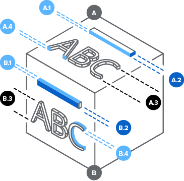
Embossed details are shallow raised features on the surface of a model like text. Small embossed features may not be visible on the finished part. Use a bold font where possible for best results with embossed text.
Minimum engraved detail
A. Horizontal faces:
A.1 Depth: 0.1 mm/100 microns
A.2 Width: 0.3 mm/300 microns
A.3 Text font height: 3.0 mm/3,000 microns
A.4 Text font depth: 0.3 mm/300 microns
B. Vertical faces:
B.1 Depth: 0.15 mm/150 microns
B.2 Width: 0.35 mm/350 microns
B.3 Text font height: 3.0 mm/3,000 microns
B.4 Text font depth: 0.3 mm/300 microns
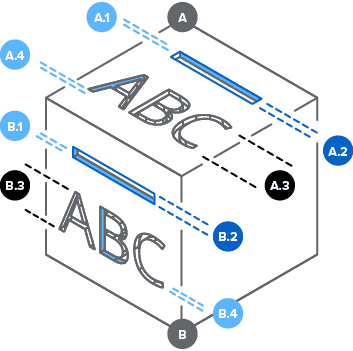
Engraved details are imprinted or recessed features on the surface of a model. Small engraved features may not be visible on the finished part. Use a bold font where possible for best results with engraved text.
Materials-specific characteristics
For the best results when printing with the Fuse Series printers, it is important to consider the unique properties of the specific material being used. The following guidelines will assist users in optimizing their designs for additive manufacturing with various powders on the Fuse Series printers.
Build volume
Due to varying thermal expansion rates for different materials, the largest parts size printable in the Fuse Series printers varies. The largest part sizes achievable are given in the table below. The maximum achievable dimensions for each material are tuned for each new print setting release, so these dimensions may change over time. The best way to ensure that your part will fit in the build chamber is to test in PreForm.
| Material | Largest Part Size |
|---|---|
| Nylon 12 Powder | 160.2 × 160.2 × 297.3 mm |
| Nylon 12 GF Powder | 159.9 × 159.9 × 294.1 mm |
| Nylon 12 Tough Powder | 158.8 × 158.8 × 293.5 mm |
| Nylon 12 White Powder | 159.9 × 159.9 × 293.8 mm |
| Nylon 11 Powder | 158.3 × 158.3 × 295.0 mm |
| Nylon 11 CF Powder | 164.6 × 164.6 × 291.7 mm |
| TPU 90A Powder | 161.2 × 161.2 × 295.0 mm |
| Polypropylene Powder | 159.4 × 159.4 × 296.0 mm |
Note:
The corners of the Fuse 1 generation build chamber are rounded. In PreForm, the inner radius of the corner is 16 mm. As a result square part that fully spans the build chamber in the X and Y directions will not be printable.
Nylon 12 Powder design considerations
Nylon 12 Powder serves as an excellent general-purpose material due to its balanced material properties, ease of printing, and ease of post-processing as well as biocompatibility. The guidelines provided in the previous sections were compiled with Nylon 12 Powder in mind, so no additional design considerations are required.
Nylon 12 GF design considerations
Nylon 12 GF Powder excels at printing stiff, thermally resistant parts that are stable under load. It also has the benefit of biocompatibility for skin-contacting applications.
Design considerations specific to this material include:
Nylon 12 Tough design considerations
Nylon 12 Tough Powder offers high ductility and high dimensional accuracy across the build chamber, allowing you to print more durable parts with less warpage, without sacrificing strength.
Design considerations specific to this material include:
Nylon 12 White design considerations
Nylon 12 White Powder combines the great qualities of Nylon 12 Powder with the customizability of white parts. Create functional prototypes and end-use customer-facing parts that can be dyed to match branding as well as medical devices and models with high contrast and detail.
Design considerations specific to this material include:
Nylon 11 Powder design considerations
Parts printed with Nylon 11 Powder offer enhanced ductility compared to the ones printed with Nylon 12 Powder. They offer greater resistance to impact and vibration and are certified for biocompatible applications.
Design considerations specific to Nylon 11 Powder include:
Nylon 11 CF Powder design considerations
Nylon 11 CF Powder is a high-performance material offering excellent stiffness, temperature resistance, impact strength, and tensile strength. It also has a lower tendency to warp than Nylon 11 Powder and therefore is more suitable to print parts with large cross sections.
TPU 90A Powder design considerations
TPU 90A Powder is an elastomer that offers high tear strength and high elongation at break. With a Shore Hardness of 90A, it is a material with firm, rubber-like characteristics. Softer parts can be achieved by substituting solid features with lattice structures to achieve targeted levels of stiffness. TPU 90A Powder is biocompatible and suitable for skin-contacting applications.
Polypropylene Powder design considerations
Polypropylene Powder is a genuine polypropylene material for 3D printing, used to produce parts with good durability and toughness. Parts produced are rigid but offer excellent ductility.
Additional resources