WHITE PAPER
Formlabs Logo

Replacing the Form Cure (2nd Generation) turntable motor

Replacing the Form Cure (2nd Generation) turntable motor

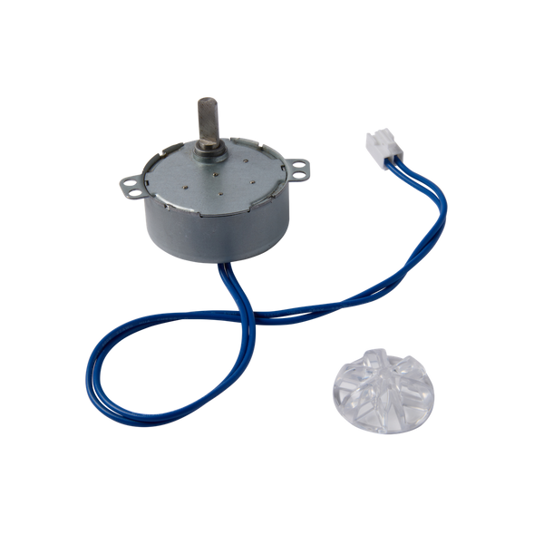
The Form Cure turntable motor assembly includes the motor and the connecting cable and powers the turntable. If the turntable motor malfunctions, the turntable may rotate indefinitely, stop rotation, or vibrate. Replace the turntable motor to restore proper functionality.

Use this guide to replace the Form Cure (2nd Generation) turntable motor.

Form Cure (2nd Generation) turntable motor

Required Supplies:

Formlabs:

  • Turntable motor
  • 2 mm hex driver (included in the Form 4/Form 4L tool caddy)
  • 2.5 mm hex driver (included in the Form 4/Form 4L tool caddy)

Third-party:

  • Nitrile gloves
  • Phillips or flat head screwdriver
  • Anti-static grounding strap
Estimated time: 40 minutes

Notice:

Formlabs devices contain sensitive electronic components. Ground yourself before touching any electronics in the machine by using an antistatic wrist band or touching a grounded piece of metal.

Preparing the workspace

Overview: Prepare the Form Cure (2nd Generation) and workspace for replacing the turntable motor.

Step 1: Prepare the workspace

Clear a workspace around your machine. Ensure that the workspace is well-ventilated and free of dust.

Step 2: Clean the Form Cure chamber

Warning:

Resin may cause skin irritation or an allergic skin reaction. Wear gloves when handling liquid resin or resin-coated surfaces. Wash skin with plenty of soap and water.

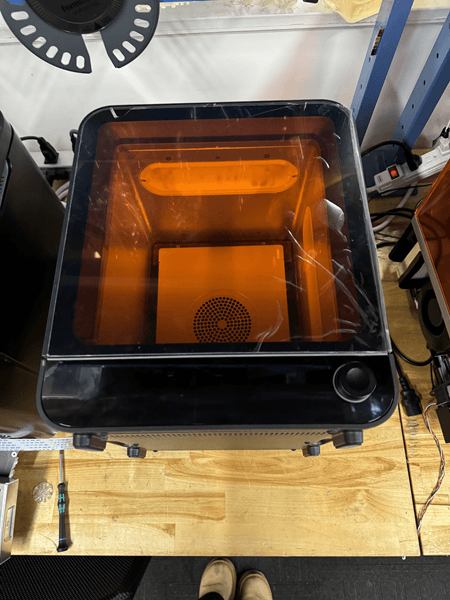
Open the Form Cure door. Clean any resin that may have pooled or cured in the post-cure chamber with paper towels. Dampen the paper towels with isopropyl alcohol if necessary.

Danger:

IPA is flammable. Keep containers closed, and keep out of the reach of children. Allow IPA to fully evaporate before starting a post-cure cycle.

Step 3: Remove the turntable

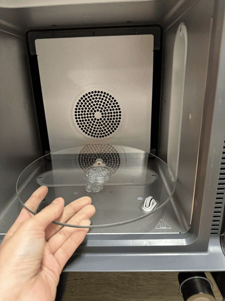
Remove the turntable

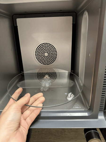
Lift the turntable directly upwards off the rollers and set it aside.

Step 4: Unplug the machine

Turn off the machine using the power switch on the back of the unit. Disconnect the power cable before continuing with maintenance. Do not perform maintenance on the machine while it is connected to power. Wait five minutes after disconnecting the machine from power before proceeding. If the machine was recently in use, the post-cure chamber will be warm. Wait at least 10 minutes for the chamber to cool.

Danger:

Performing maintenance on the machine while it is plugged in increases the risk of electric shock. Never remove the machine's shells while it is plugged in. Never reconnect the machine to power while the shells are uninstalled.

Removing the turntable motor

Overview: Remove the bottom access panel, disconnect cables, and loosen the bottom shell to remove the turntable motor.

Step 1: Position the machine

Position the machine
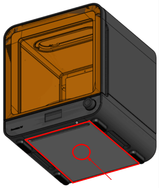
Locate bottom access panel

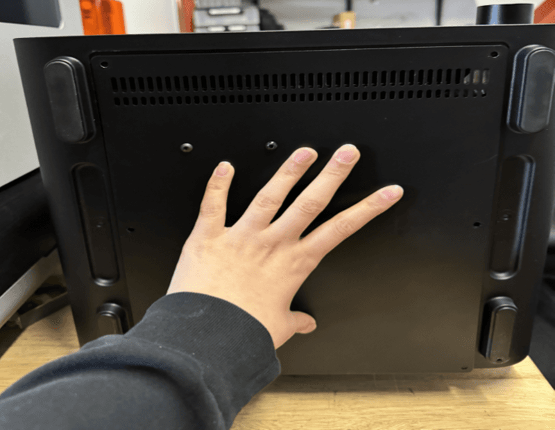
Ensure that the turntable has been removed from the machine to prevent damage. Carefully rotate the machine so that it is resting on the back surface with the bottom facing you. Leave at least 15 cm (6 in) of clear tabletop in front of the machine when it is lying down.

Step 2: Remove the bottom access panel screws

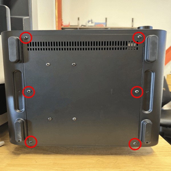
Remove the bottom access panel screws

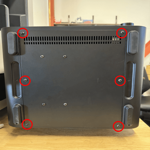
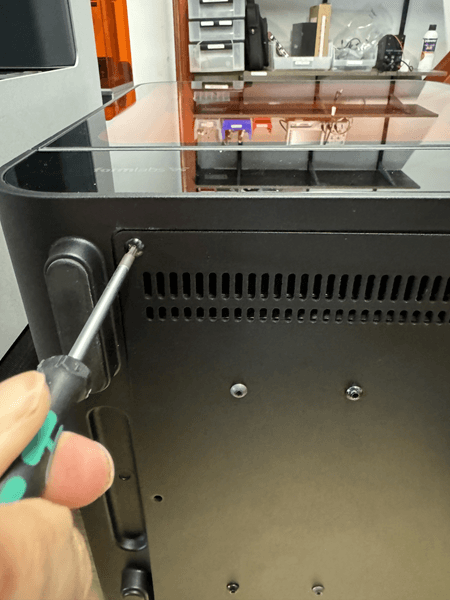
Use a 2.5 mm hex driver to remove the six screws that secure the bottom access panel to the machine. Set the panel and the screws aside.

Step 3: Remove the cap seal

Remove the cap seal

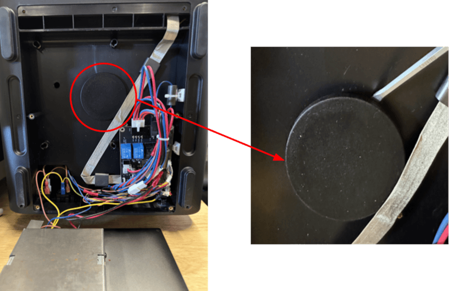
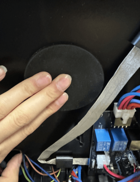
The turntable motor is located underneath a cap seal. Use a flat-head driver to remove the cap seal. Set the cap seal aside for later reinstallation.

Step 4: Locate the motor cable

Locate the motor cable
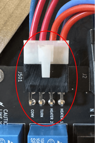
Close up of TURN on control board

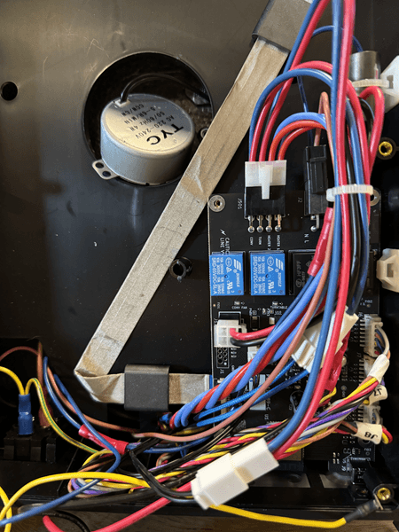
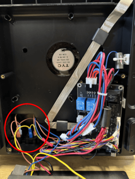
Locate the control board on the bottom right side of the machine. The motor cable connects to the control board in the port labeled TURN near the top left side of the board.

Step 5: Disconnect the motor cable

Disconnect the motor cable

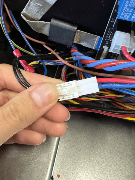
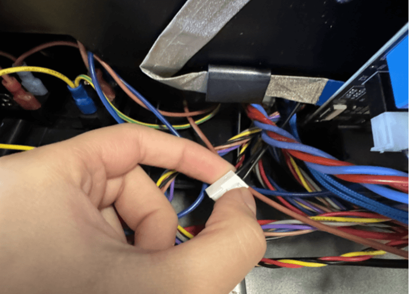
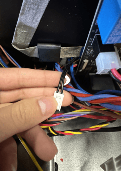
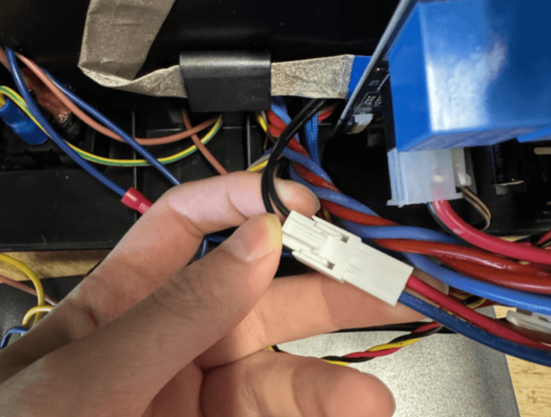
Follow the red and blue motor cable to the plastic housing connecting it to the black motor cable. Hold the connector by its plastic housing and gently squeeze the plastic tab to unplug the motor cables. Do not unplug the red and blue motor cables from the control board. Do not pull on the individual wires.

Step 6: Remove the control board screws

Remove the control board screws

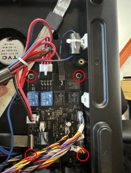
Using a 2 mm hex driver, unscrew and remove the four screws securing the control board to the machine. Set the screws aside. Allow the control board to hang loosely in front of the machine. Do not pull any cables. Do not remove any cables.

Step 7: Remove the turntable motor screws

Remove the turntable motor screws
alttext

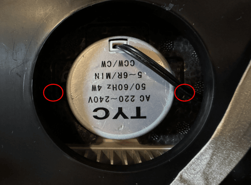
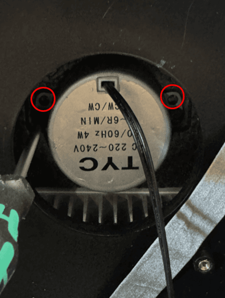
Using a 2.5 mm hex driver, unscrew and remove the two turntable motor screws securing the turntable motor to the machine. Take care not to drop the screws in the machine. Set the screws aside. Allow the turntable motor to rest along the machine. Do not pull the turntable motor away from the machine until the motor cable is disconnected.

Step 7: Remove the bottom shell screws

Remove the bottom shell screws

Using a 2.5 mm hex driver, unscrew and remove the four screws securing the bottom shell to the machine. Set the screws aside.

Step 8: Tilt the bottom shell

Tilt the bottom shell

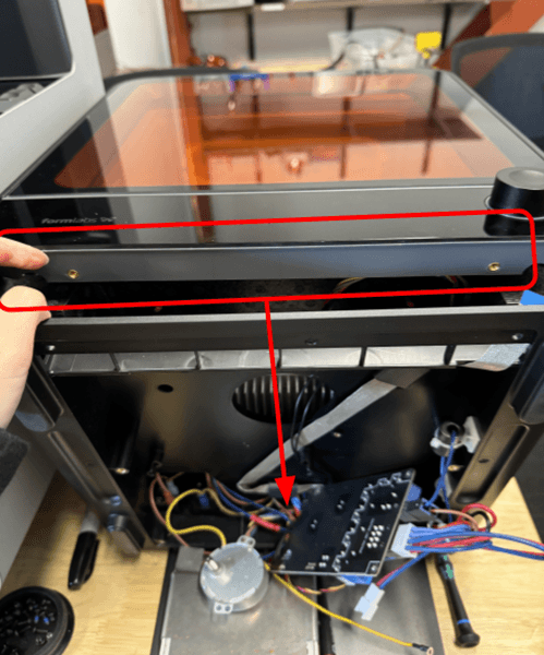
Gently tilt the bottom shell away from the machine to access the internal cavity. Do not force the panel open, as it is still attached to the machine.

Step 9: Remove the motor cable

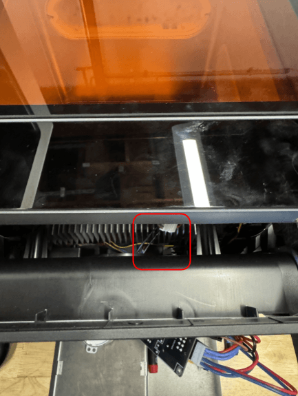
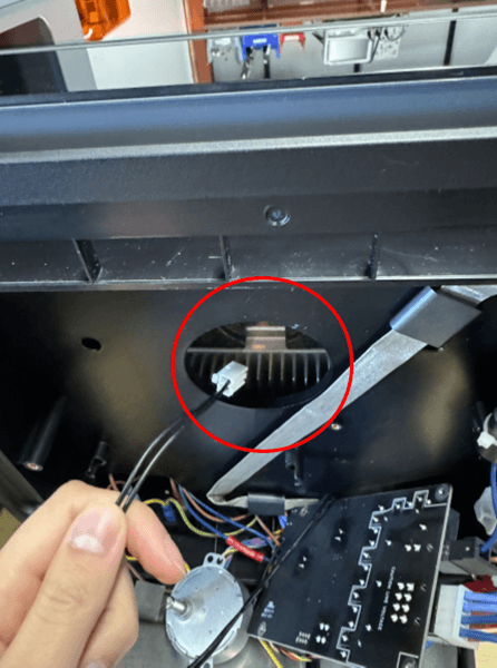
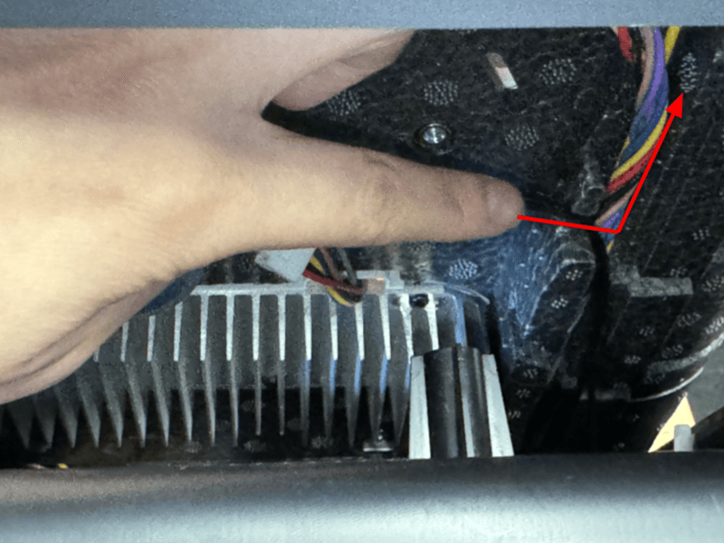
Reach into the machine and free the black motor cable from the machine.
Remove the motor cable through the opening in the bottom shell.

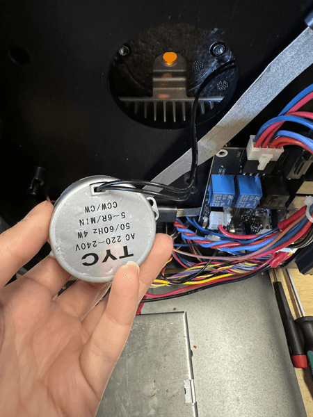
Reach into the machine and free the black motor cable from the machine. Remove the motor cable through the opening in the bottom shell. Remove the turntable motor and motor cable from the machine. Set aside for disposal with electronic waste.

Installing the replacement turntable motor

Overview: Plug in and install the replacement turntable motor.

Step 1: Mount and secure the turntable motor

Secure the turntable motor

Mount the replacement turntable motor through the opening in the bottom shell, aligning its screw holes with those in the panel. Take care that the motor is oriented with the label upside down. Thread one motor retention screw into each of the screw holes. Use a 2.5 mm hex driver to tighten until snug.

Step 2: Route the motor cable through the machine

Gently pull the bottom shell away from the machine to access the insulation below.
Press the motor cable through the grooved pathway alongside the multicolored LED module cable harness.

Route the motor cable through the opening in the bottom shell. Gently pull the bottom shell away from the machine to access the insulation below. Press the motor cable through the grooved pathway alongside the multicolored LED module cable harness.

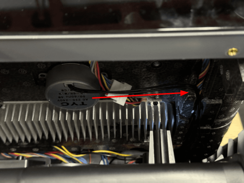
Route the motor cable through the slot at the bottom of the internal panel.
Gently pull the motor cable by the plastic housing through the slot.

Route the motor cable through the slot at the bottom of the internal panel. Gently pull the motor cable by the plastic housing through the slot.

Step 3: Connect the motor cable to the control board

Connect the motor cable to the control board

Press the plastic housing to connect the motor cable to the red and blue wires connected to the control board in the port labeled TURN.

Step 4: Secure the bottom shell

Secure the bottom shell

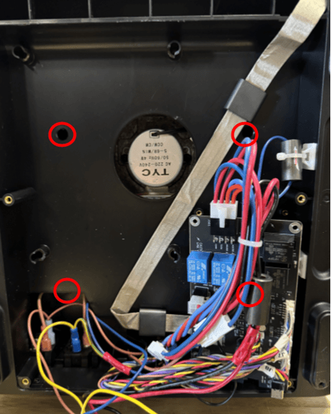
Thread one bottom shell screw into each of the four screw holes. One screw hole is located underneath the control board. Use a 2.5 hex driver to tighten until finger tight.

Step 5: Mount and secure the control board

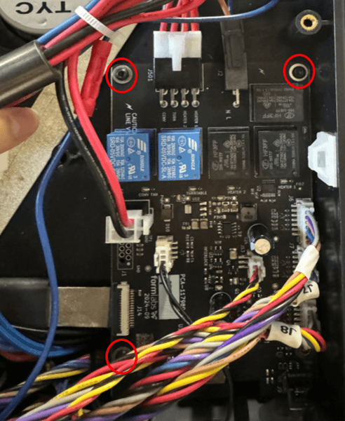
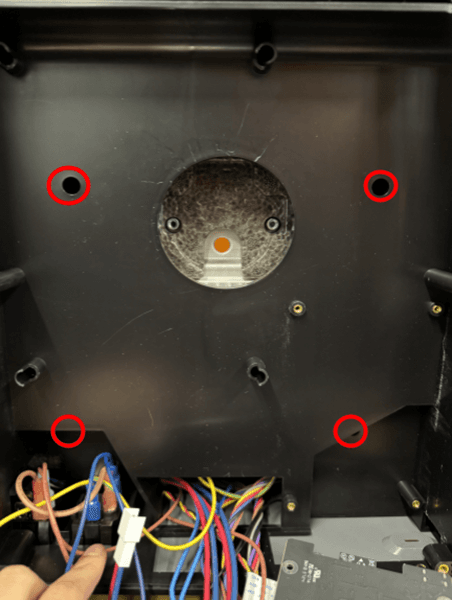
 Thread one control board screw into each of the three screw holes highlighted in red.
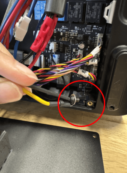
Thread the yellow cable ring terminal through the remaining screw into the lower right corner.

Thread one control board screw into each of the three screw holes highlighted in red. Thread the yellow cable ring terminal through the remaining screw into the lower right corner. Use a 2 mm hex driver to tighten until finger tight.

Step 5: Reinstall the cap seal

Reinstall the cap seal

Press the cap seal into place in the opening of the bottom shell. The edges of the cap seal should lay flush with the bottom shell.

Step 6: Reinstall the bottom access panel

Reinstall the bottom access panel

Lift the bottom access panel and mount it on the machine. Ensure that the six bottom access panel retention screw holes are aligned.

Step 7: Secure the bottom access panel

Secure the bottom access panel

Thread one screw into each of the six screw holes in the bottom access panel. Using a 2.5 mm hex driver, tighten the screws until finger tight.

Step 8: Reposition the machine

Lift the machine so it is right-side up.

Finalizing the repair

Overview: After installing the replacement turntable motor, power on the machine and perform final checks.

Step 1: Insert the turntable

Insert the turntable

Place the turntable onto the turntable mount.

Step 2: Power on the machine

Close the Form Cure door. Connect the power cable to the Form Cure and the power supply. Flip the breaker switch on the back of the unit to the ON position to turn on the machine. The Form Cure initializes.

Step 3: Test the repair

Start a post-cure cycle. Contact Formlabs Support or your authorized reseller to share the results of the procedure.