
Required supplies:
Formlabs:
- Replacement tubing (available on the Formlabs Store)
- T20 Torx driver (provided with the Fuse Blast)
- 7 mm nut driver (provided with the Fuse Blast)
Third-party:
- 6.5 mm slotted screwdriver

The Fuse Blast has a variety of internal tubes for handling air and blasting or polishing media. Sometimes, an issue related to air or media flow may require inspecting or replacing some of this tubing. To access, inspect, clean or replace a specific length of tubing, refer to the notes in the relevant section of this document to determine which enclosure panels need to be removed.
Using this guide to inspect or replace tubing within the Fuse Blast.
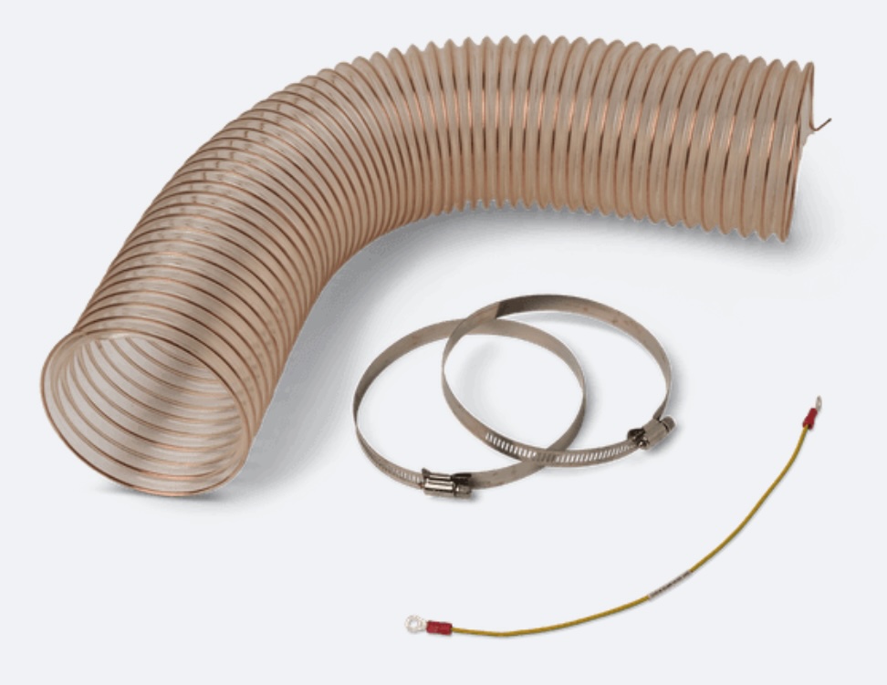
Required supplies:
Formlabs:
Third-party:
Estimated time: 30–45 minutes, depending on the tubing to be inspected or replaced
Preparing the workspace
Overview: Prepare the Fuse Blast and a clean workspace for replacing the motherboard and display assembly.
Step 1: Prepare the workspace
Clear a workspace. Ensure that the workspace is well-ventilated, level, and clean.
Step 2: Unplug the machine
Disconnect the power cable from the machine before continuing with maintenance. Do not perform maintenance on the machine while it is connected to power. Wait five minutes after disconnecting the printer from power before proceeding.
Danger:
Performing this procedure on the Fuse Blast while it is plugged in increases the risk of electric shock. Never remove any external paneling while the Fuse Blast is plugged in. Never reconnect the Fuse Blast to power while the external paneling is uninstalled.
Step 3: Determine which panels need to be removed
Which panels you need to remove from your Fuse Blast is a function of which tubing you need to access, inspect, or replace. Check the section for the tubing you are working on to determine which panels need to be removed:
Removing the the rear enclosure panel
Overview: Remove the rear enclosure panel to access some of the internal Fuse Blast tubing.
Step 1: Unscrew the rear enclosure panel mounting screws
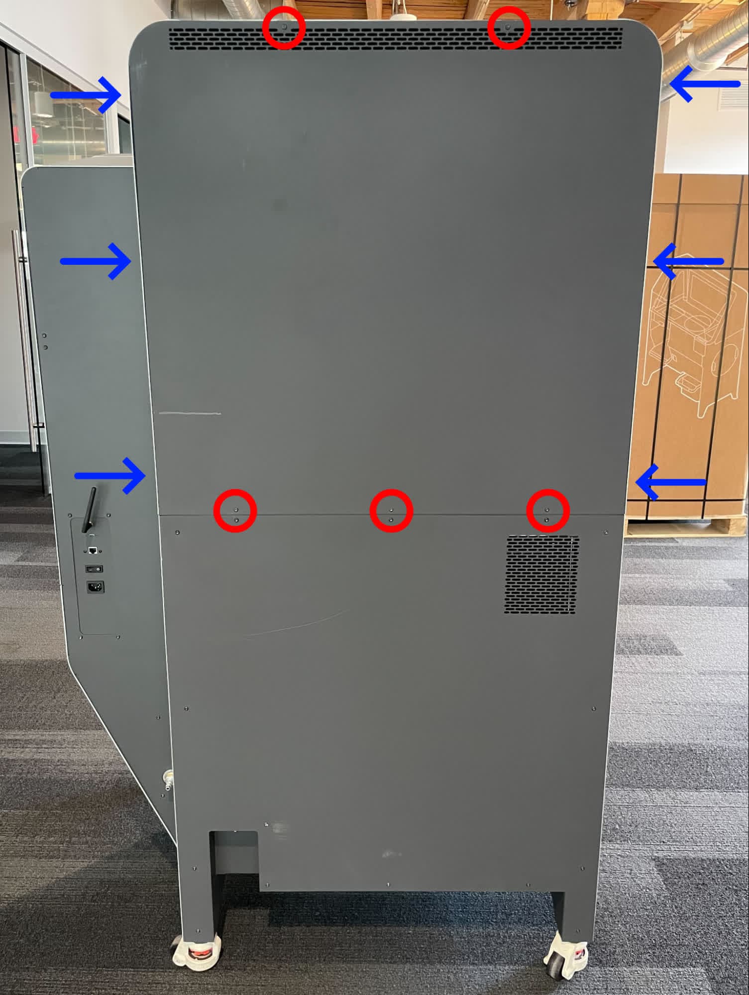
Using a T20 Torx driver, remove the five black oxide Torx screws (on the back of the unit, marked with red circles here) and the six chrome Torx screws (along the sides of the unit, marked with blue arrows here) securing the rear enclosure panel to the Fuse Blast. Set the screws aside.
Step 2: Remove the rear enclosure panel
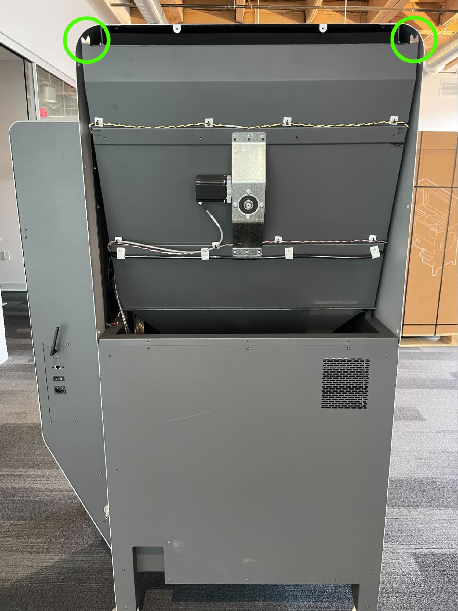
Slide the rear enclosure panel up to free the locating features, then remove the panel. Set the panel aside.
Removing the back base panel
Overview: Remove the back base panel to access some of the internal Fuse Blast tubing.
Step 1: Unscrew the back base panel mounting screws
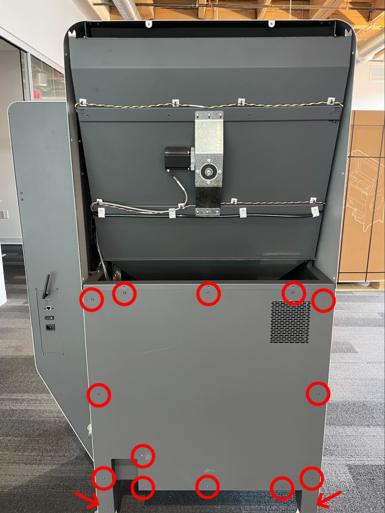
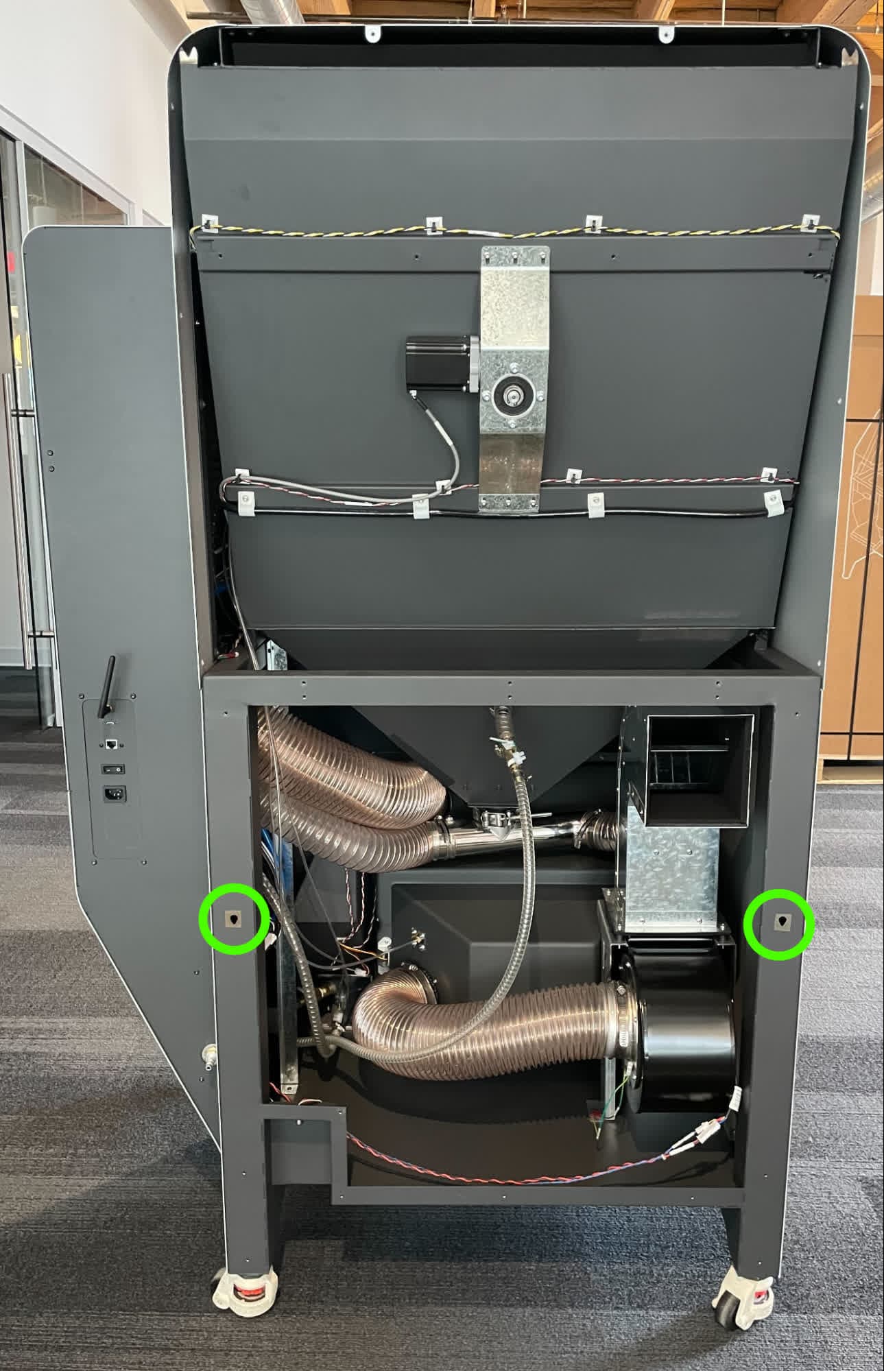
Using a T20 Torx driver, remove the 15 black oxide Torx screws securing the back base panel to the Fuse Blast. Set the screws aside.
Step 2: Remove the back base panel
Slide the back base panel up to free the locating features, then remove the panel. Set the panel aside.
Removing the left enclosure panel
Overview: Remove the left enclosure panel to access some of the internal Fuse Blast tubing.
Step 1: Unscrew the left enclosure panel mounting screws
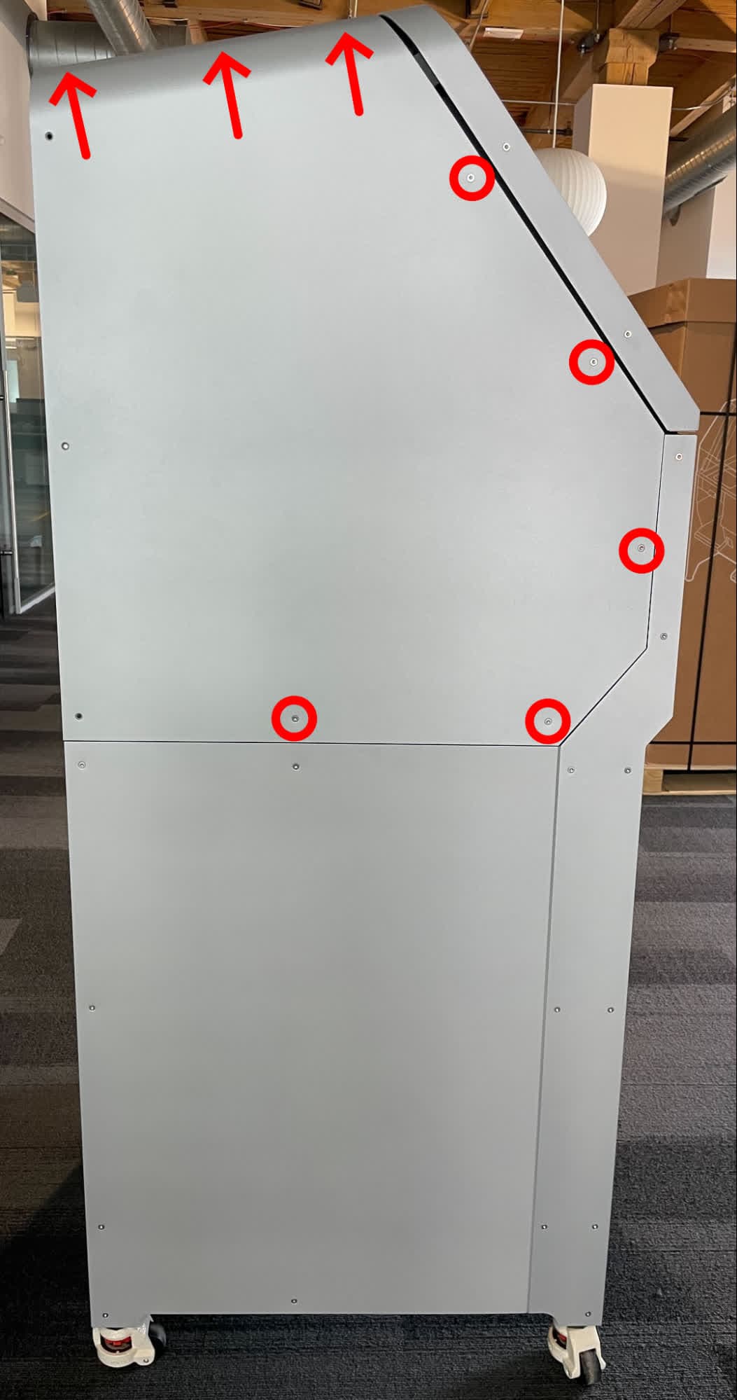
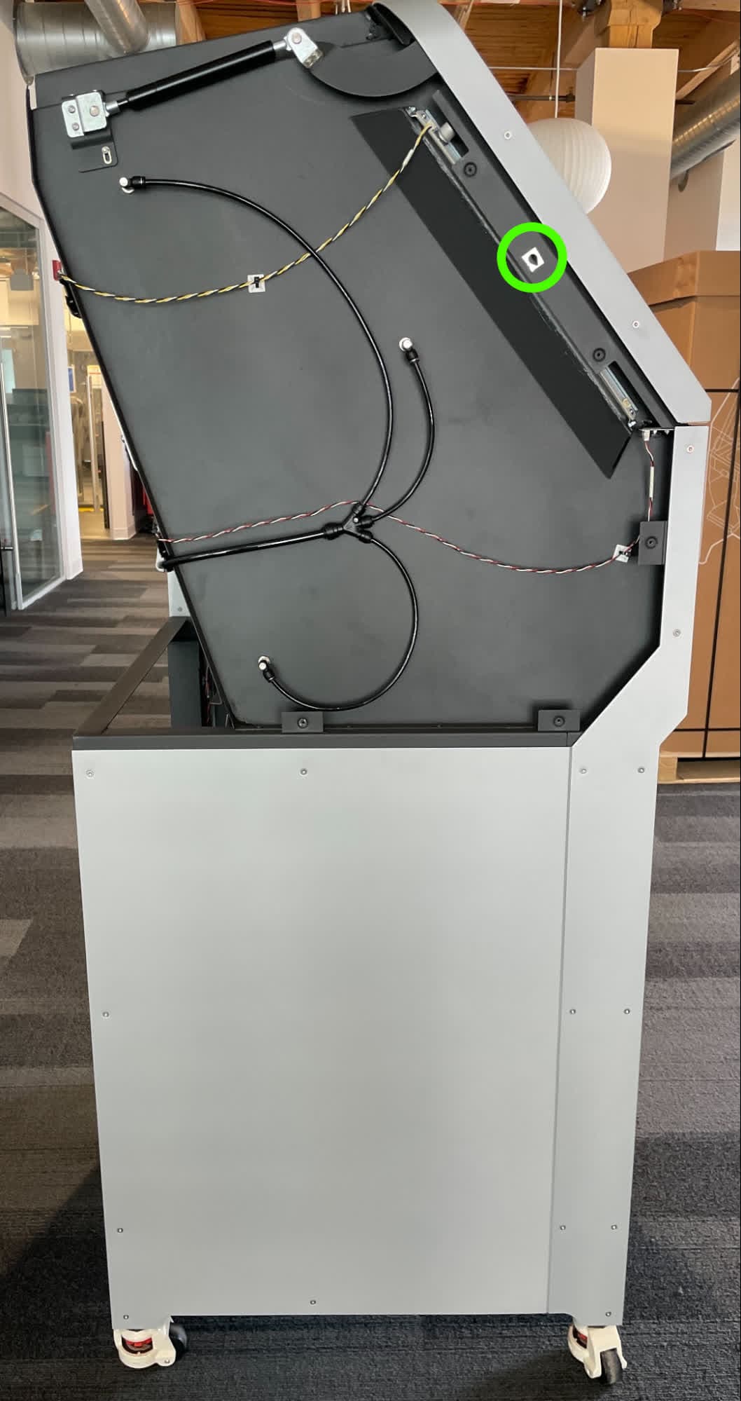
Using a T20 Torx driver, remove the eight black oxide Torx screws securing the left enclosure panel to the Fuse Blast. Set the screws aside.
Step 2: Remove the left enclosure panel
Slide the left enclosure panel up to free the locating feature, then remove the panel. Set the panel aside.
Removing the left base panel
Overview: Remove the left base panel to access some of the internal Fuse Blast tubing.
Step 1: Unscrew the left base panel mounting screws
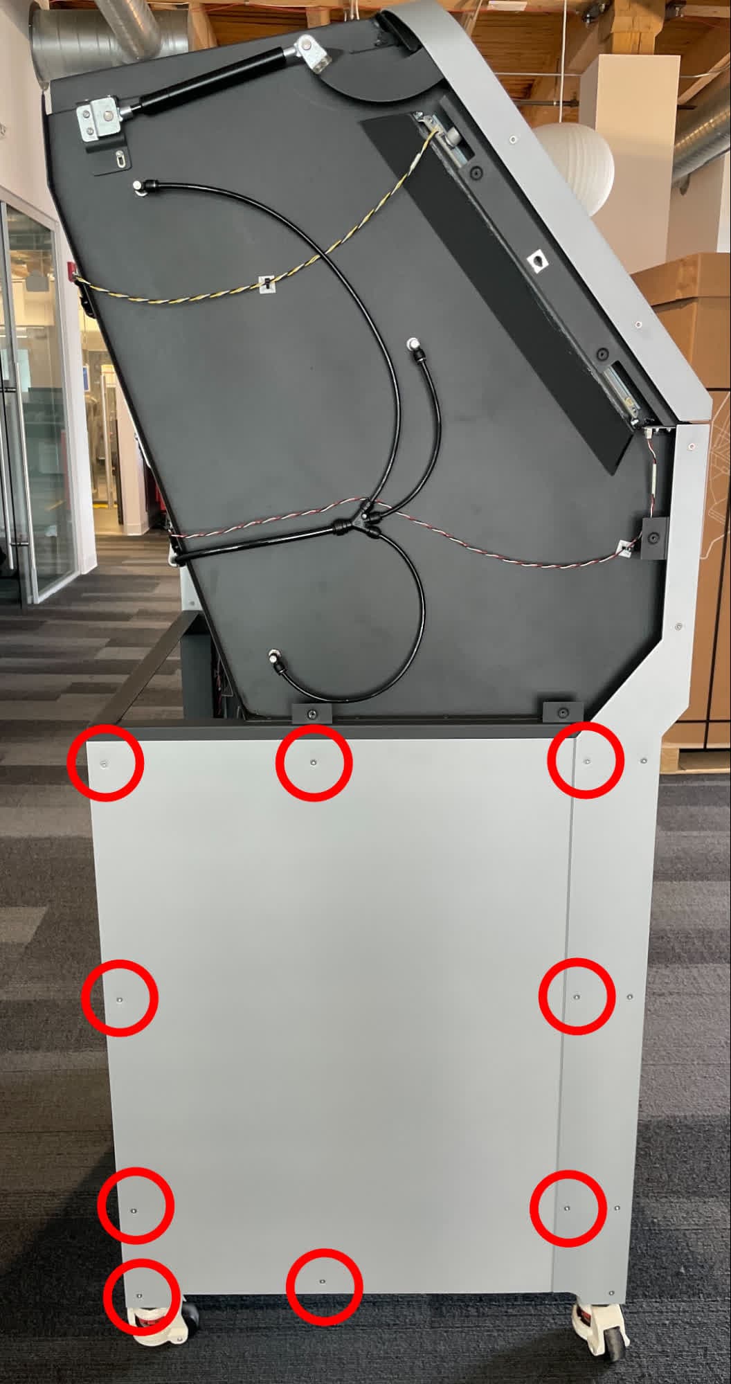
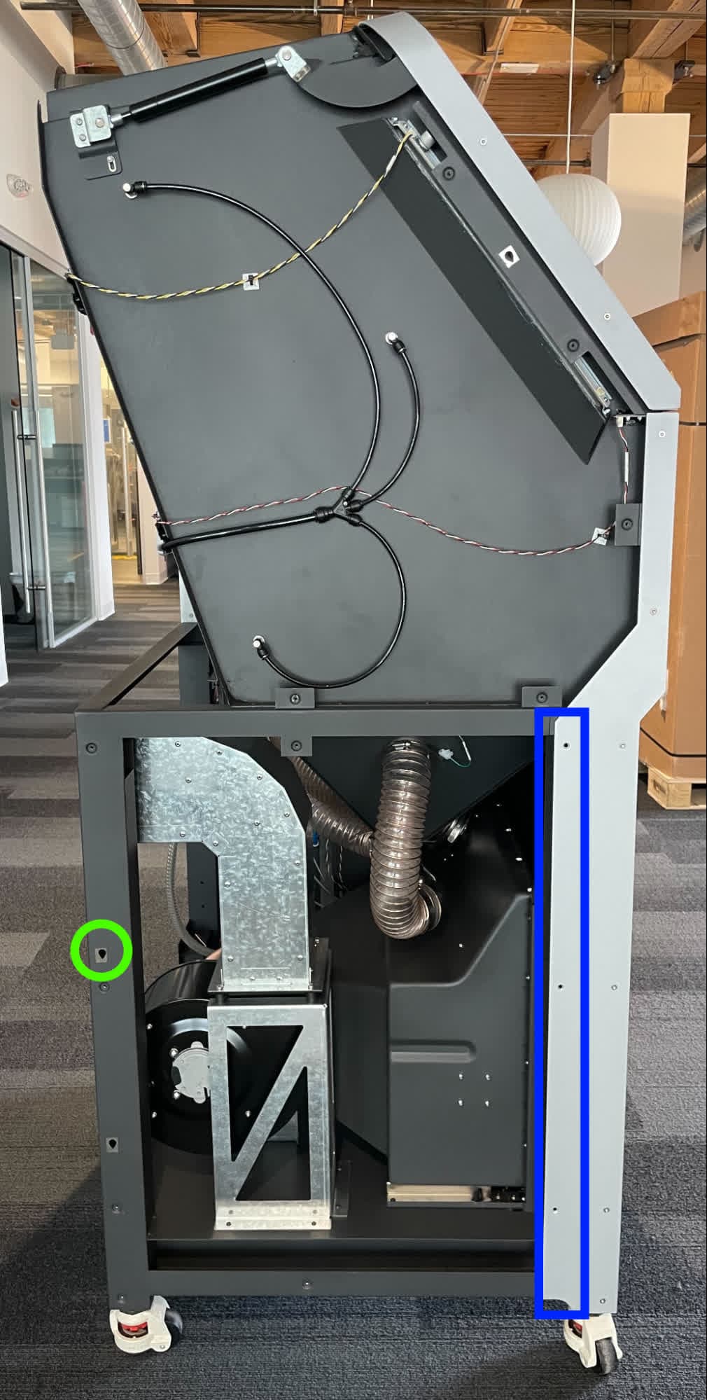
Using a T20 Torx driver, remove the nine black oxide Torx screws securing the left base panel to the Fuse Blast. Set the screws aside.
Step 2: Remove the left base panel
Slide the left base panel up to free the locating feature, then move the panel left to free the flange on the right Remove the panel and set it aside.
Removing the right enclosure panel
Overview: Remove the right enclosure panel to access some of the internal Fuse Blast tubing.
Step 1: Unscrew the right enclosure panel mounting screws
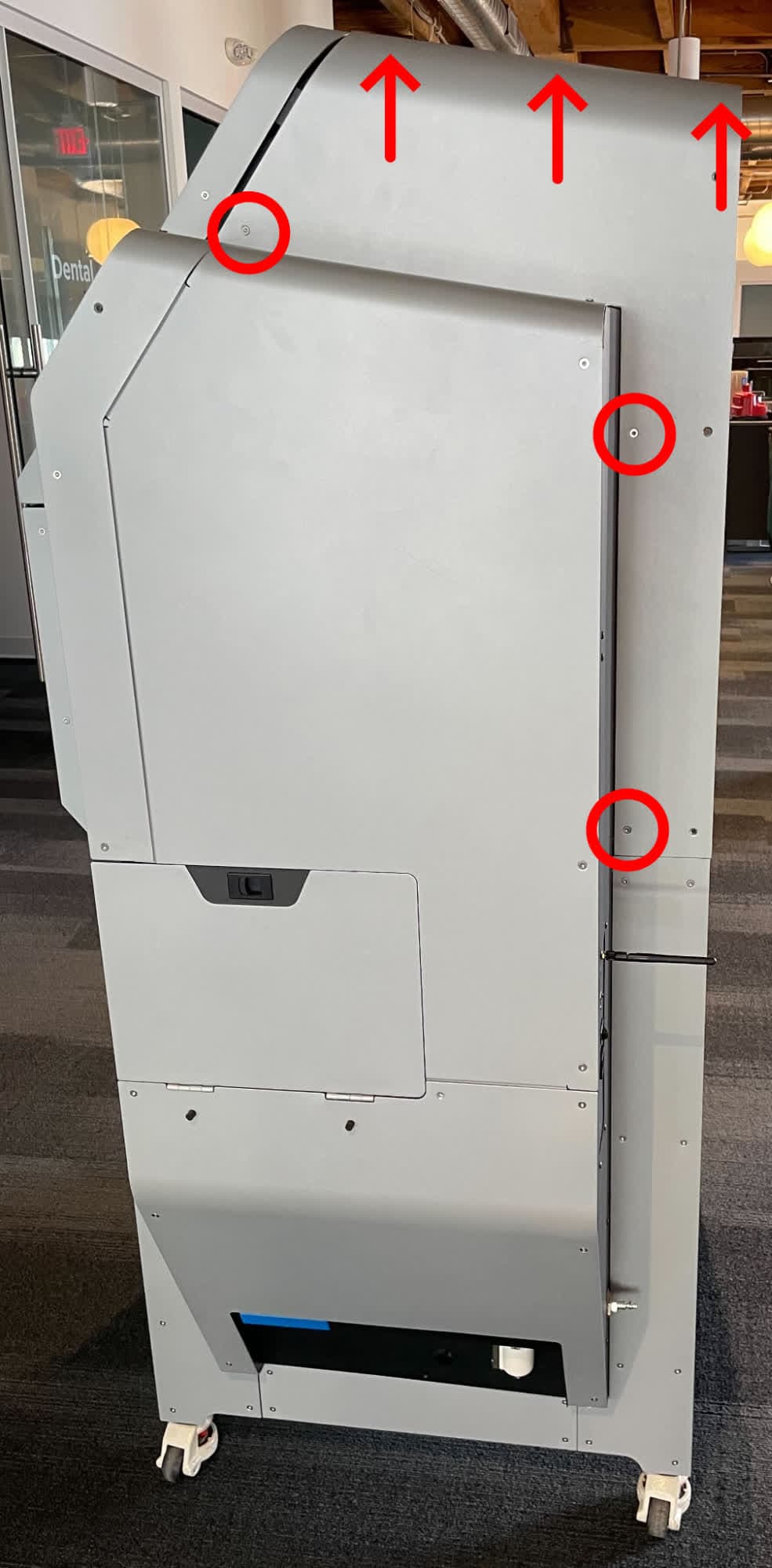
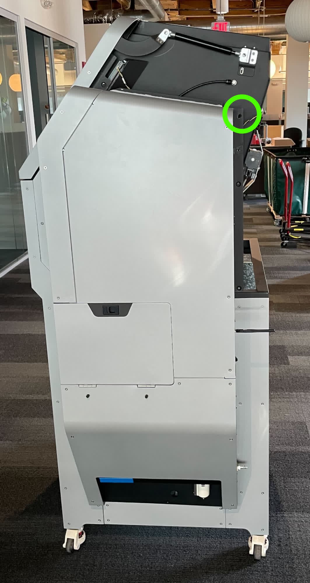
Using a T20 Torx driver, remove the five black oxide Torx screws securing the right enclosure panel to the Fuse Blast. Set the screws aside.
Step 2: Remove the right enclosure panel
Slide the right enclosure panel up to free the locating feature, then remove the panel. Set the panel aside.
Removing the upper sidecar panel
Overview: Remove the upper sidecar panel to access some of the internal Fuse Blast tubing.
Note:
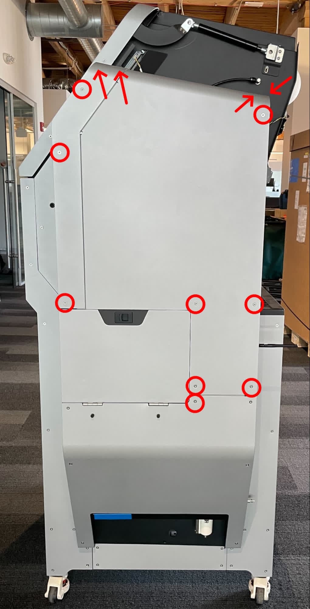
The right enclosure panel or the lower sidecar panel needs to be removed before you can remove the upper sidecar panel. If the right enclosure panel is still in place, rotate the sidecar panel(s) up to free the top flange from under the right enclosure panel.
Step 1: Unscrew the upper sidecar panel mounting screws
Using a T20 Torx driver, remove the 13 black oxide Torx screws securing the upper sidecar panel to the Fuse Blast. Set the screws aside.
Step 2: Remove the upper sidecar panel
Slide the upper sidecar panel up to free the flange on the bottom, then remove the panel. Set the panel aside.
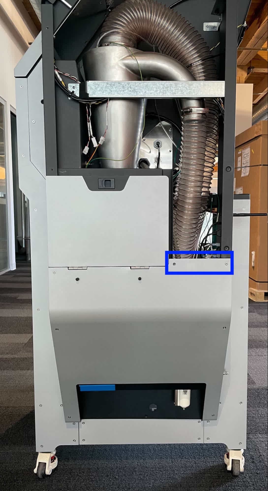
Removing the lower sidecar panel
Overview: Remove the lower sidecar panel to access some of the internal Fuse Blast tubing.
Step 1: Unscrew the lower sidecar panel mounting screws
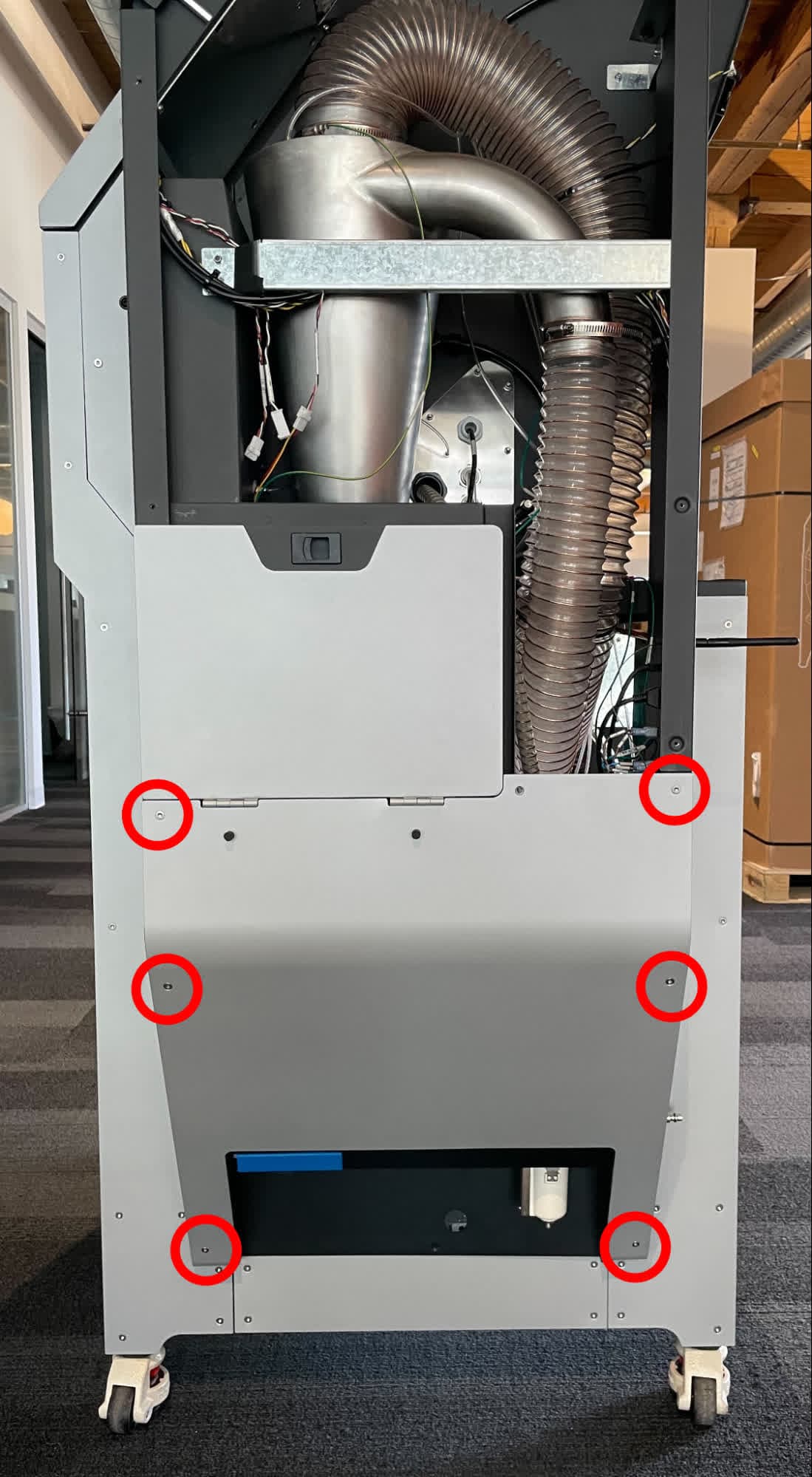
Using a T20 Torx driver, remove the six chrome Torx screws securing the lower sidecar panel to the Fuse Blast. Set the screws aside.
Step 2: Remove the lower sidecar panel
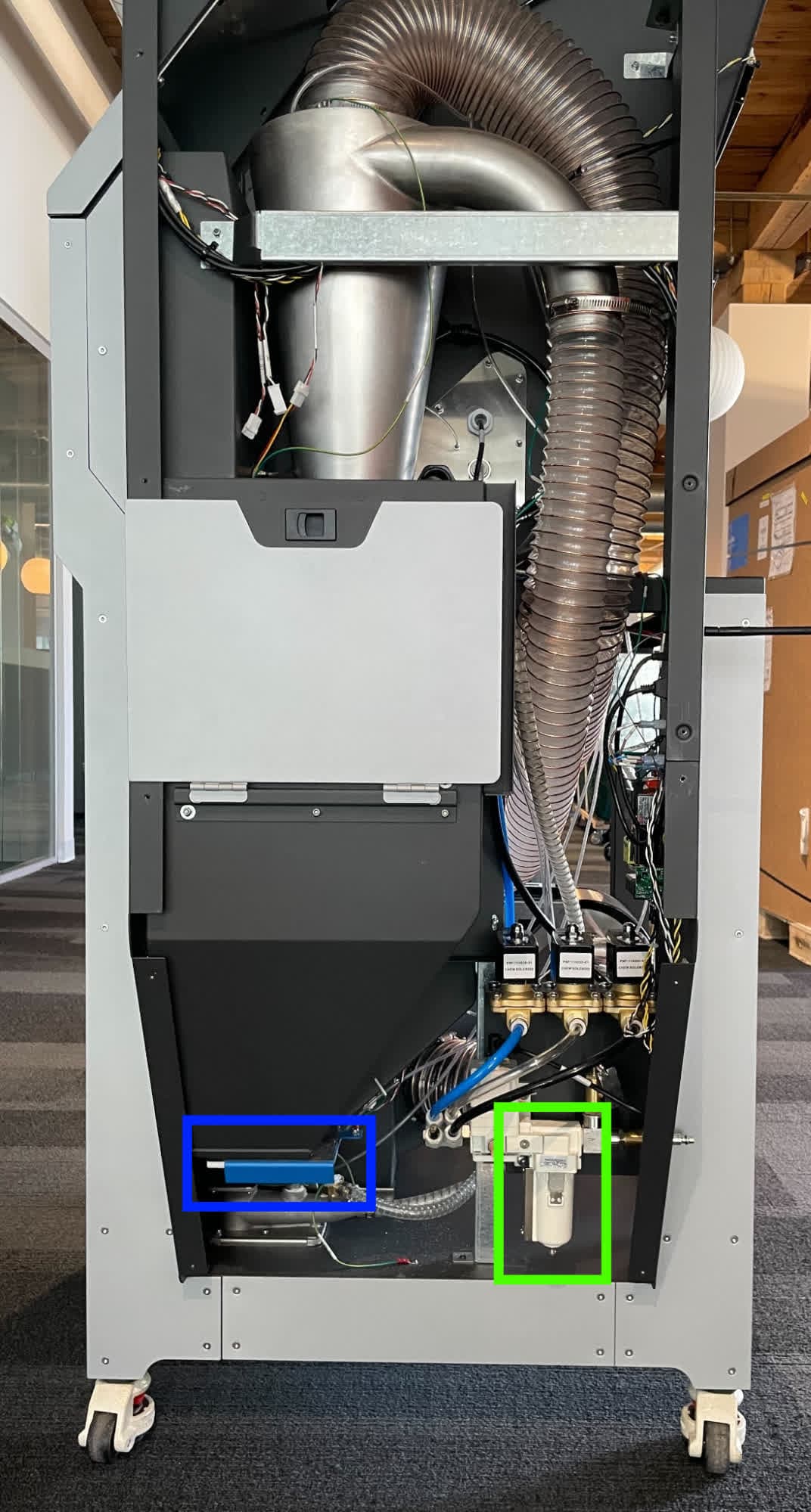
Slide the lower sidecar panel down around the waste hopper knife valve and the pneumatic filter. Remove the pneumatic filter if necessary. Set the panel aside.
Inspecting or replacing the pneumatic cassette tubing
Step 1: Access the tubing
To access the pneumatic cassette tubing, remove the lower sidecar panel.
Step 2: Disconnect the compressed air source
If you have not done so already, disconnect your compressed air source from the Fuse Blast inlet before performing any service on the pneumatic cassette tubing.
Step 3: Disconnect the pneumatic cassette tubing
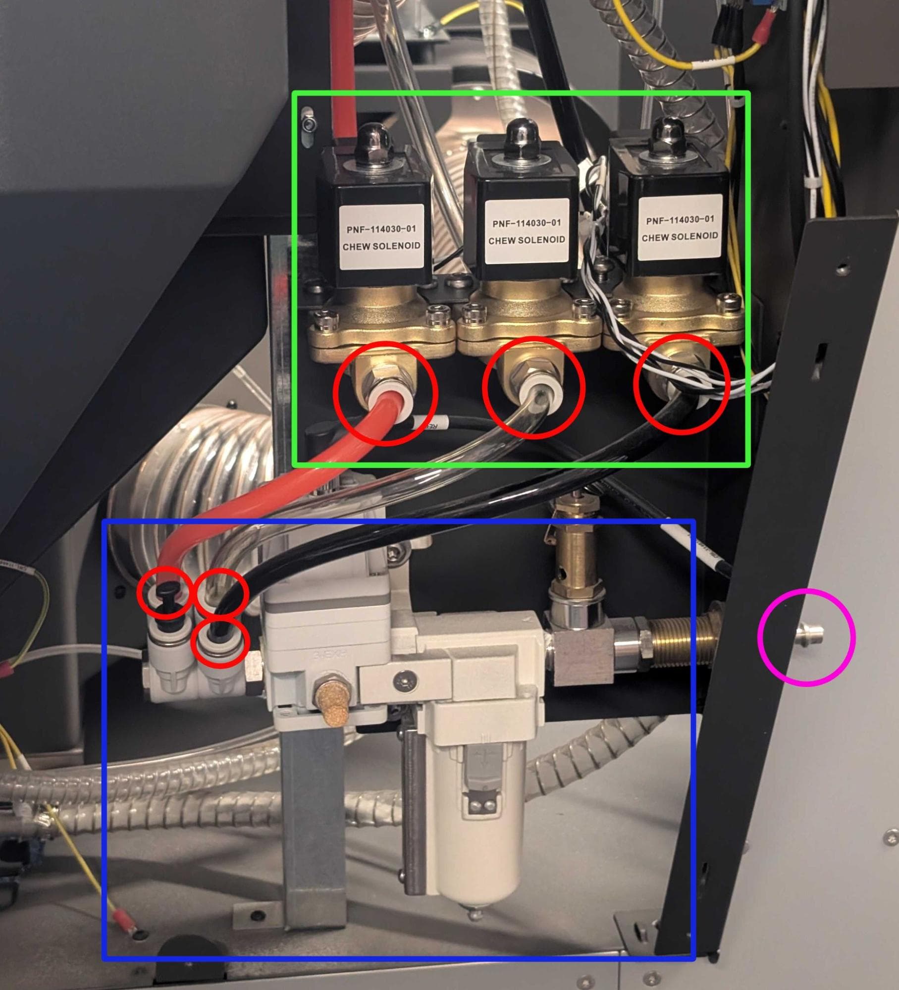
Press on the push-to-connect fitting for the relevant tubing on the pressure manifold and solenoid valves, then pull the tube out. The tubing is color-coded red for blast, clear for part rinse, and black for chamber rinse.
Step 4: Reconnect the tubing
When you are done inspecting the tubes, push each back into its respective push-to-connect fitting. If you are replacing any of the tubes, install the replacement instead.
Inspecting or replacing the blast and part rinse air tubing
Overview: Access the blast and part rinse tubes to inspect or replace them.
Step 1: Access the tubing
To access the blast and part rinse tubing, remove the upper and lower sidecar panels.
Step 2: Disconnect the compressed air source
If you have not done so already, disconnect your compressed air source from the Fuse Blast inlet before performing any service on the blast or part rinse tubing.
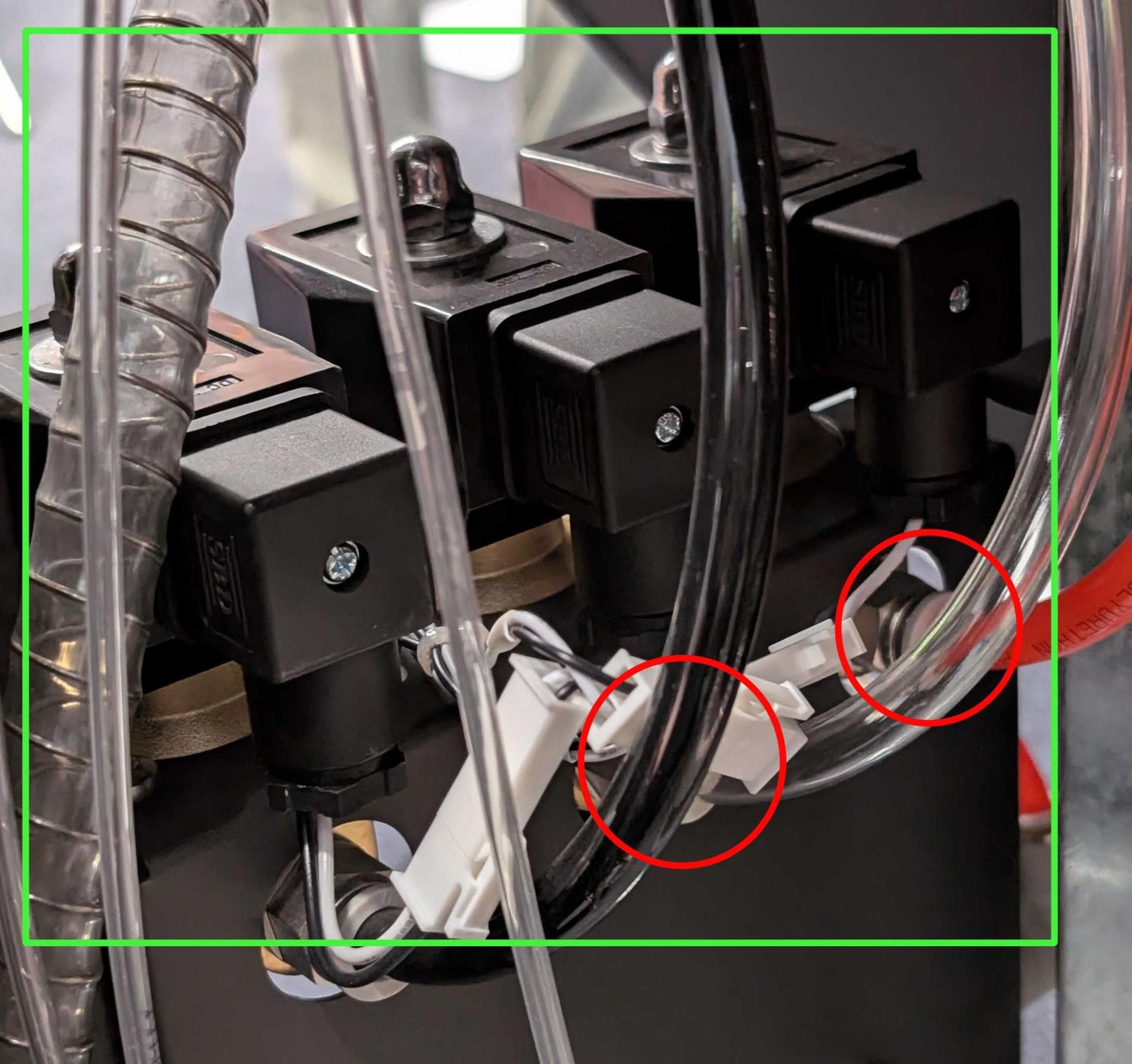
Step 3: Disconnect the blast and part rinse air tubing from the pneumatic cassette solenoids
Press on the push-to-connect fitting for the relevant tubing on the rear of the solenoid valves, then pull the tube out. The tubing is color-coded red for blast and clear for part rinse.
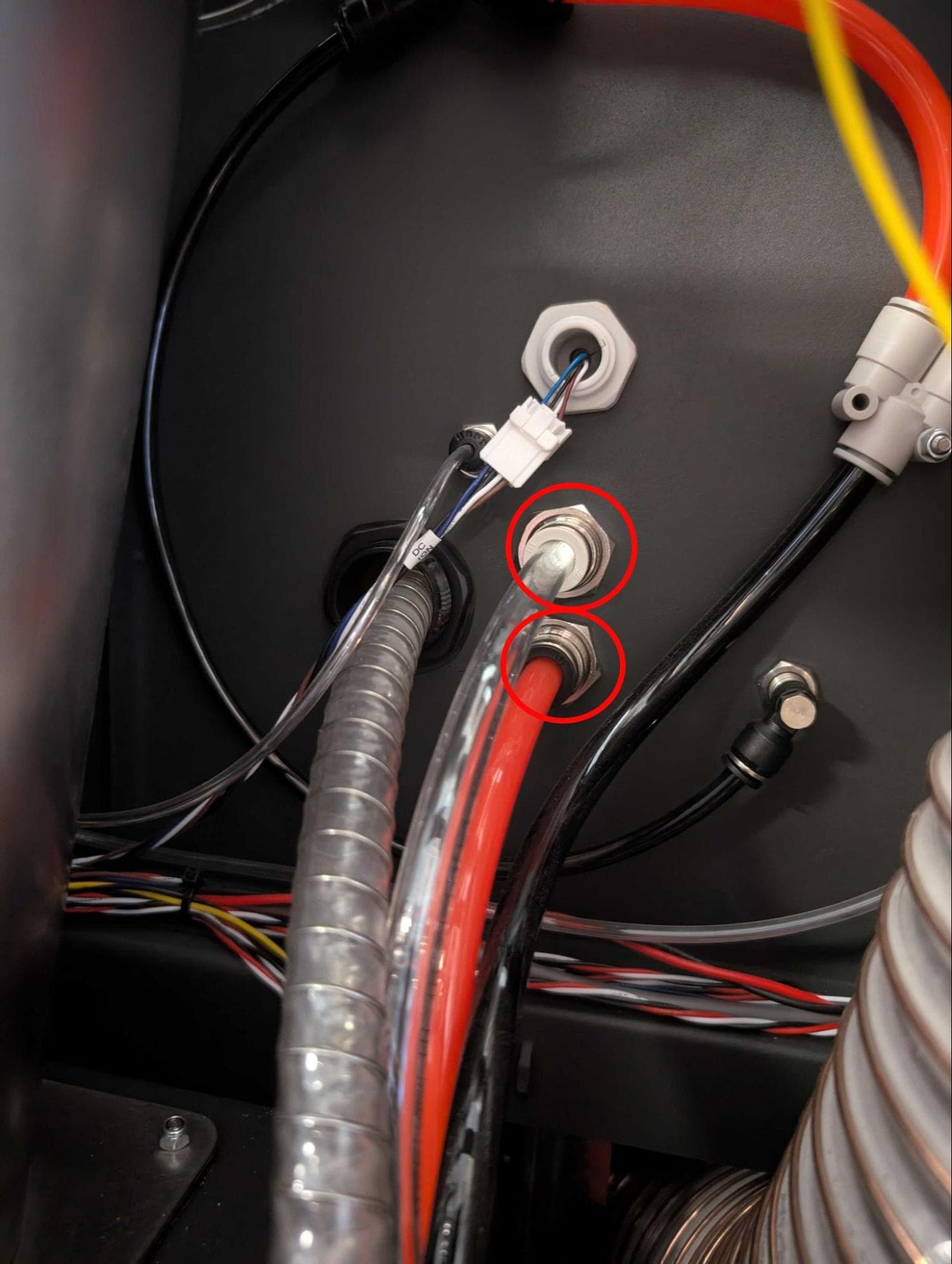
Step 4: Disconnect the other end of the blast and part rinse air tubing
Press on the push-to-connect fitting for the relevant tubing on the right side of the blast cabinet, then pull the tube out.
Step 5: Reconnect the tubing
When you are done inspecting the tubes, push each back into its respective push-to-connect fitting. If you are replacing either of the tubes, install the replacement instead.
Inspecting or replacing the chamber rinse tubing
Overview: Access the various tubes used for the chamber air rinse to inspect or replace them.
Step 1: Access the tubing
To access the chamber rinse tubing, remove the upper and lower sidecar panels as well as the right, left, and rear enclosure panels.
Step 2: Disconnect the compressed air source
If you have not done so already, disconnect your compressed air source from the Fuse Blast inlet before performing any service on the chamber rinse tubing.
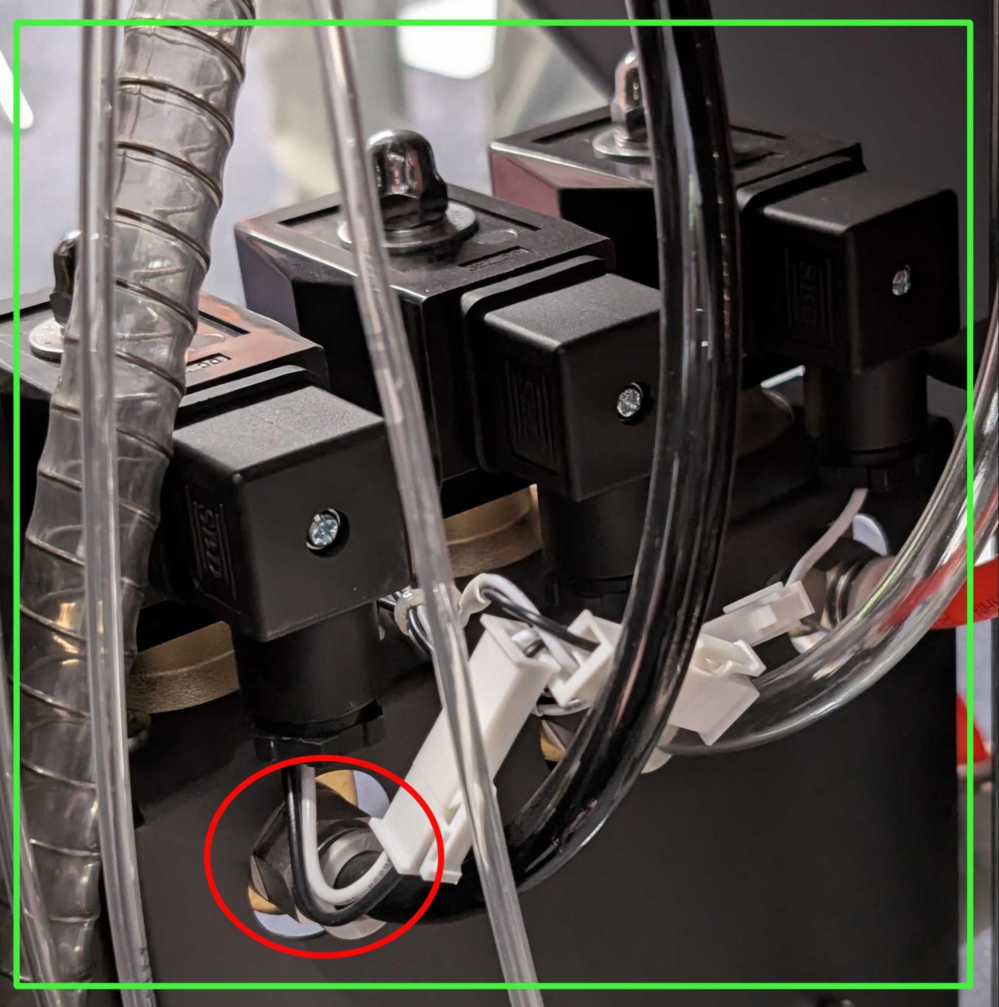
Step 3: Disconnect the chamber rinse tubing from the pneumatic cassette solenoid
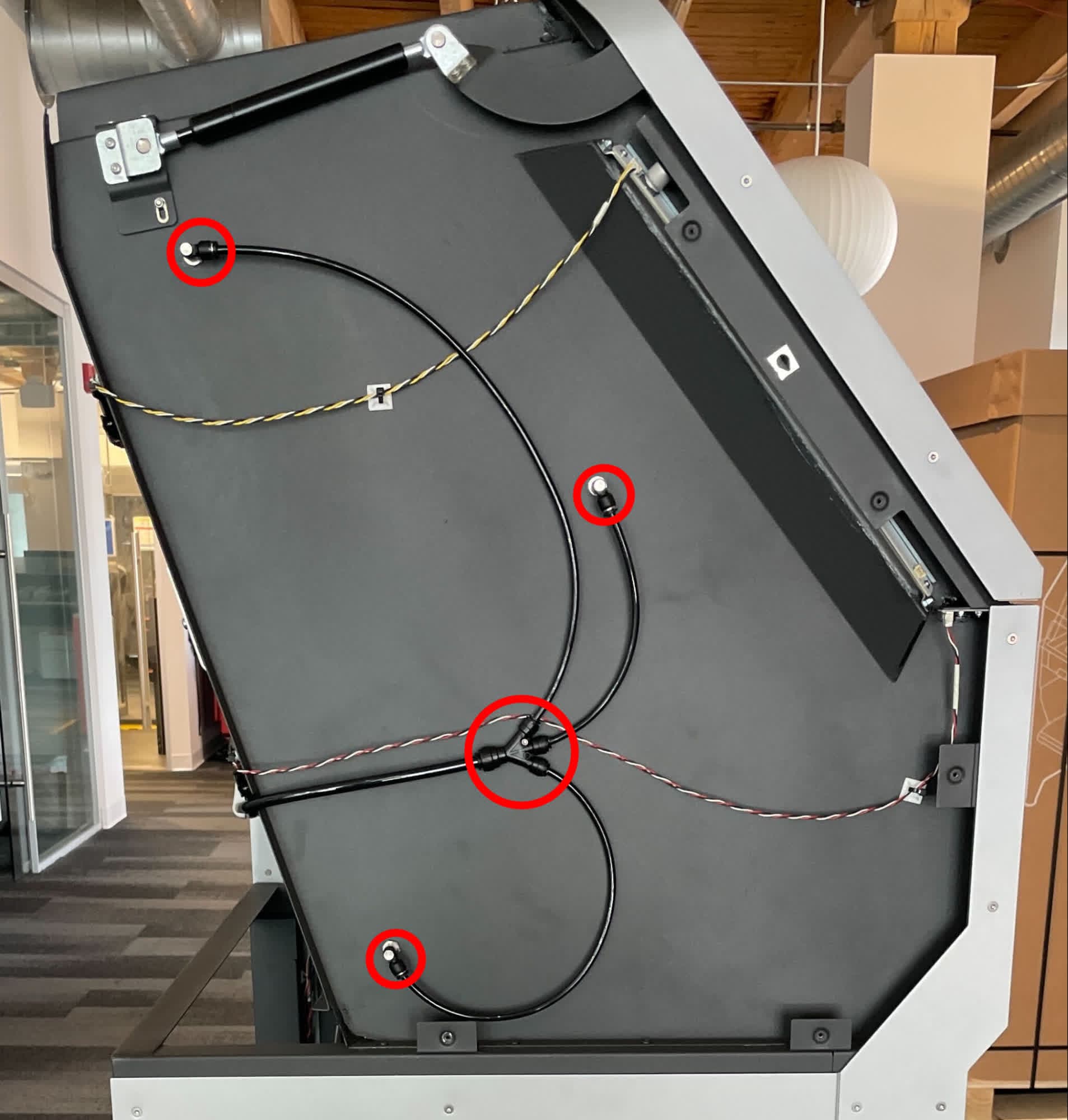
Press on the push-to-connect fitting for the back chamber rinse tubing on the solenoid valve, then pull the tube out.
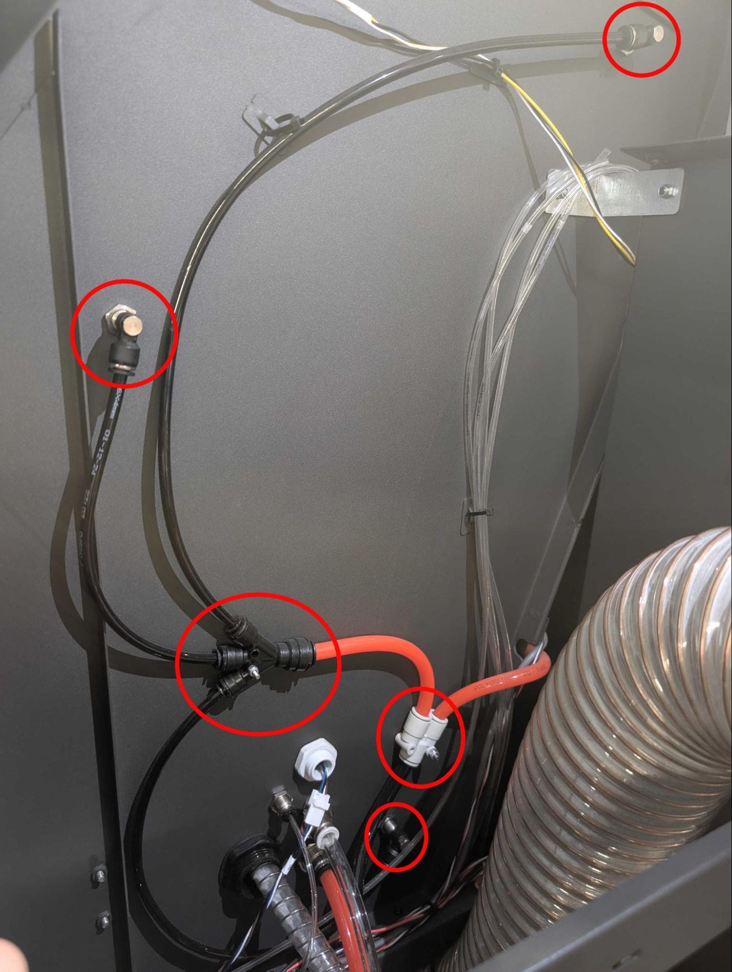
Step 4: Disconnect the chamber rinse tubing from the right side of the Fuse Blast
Press on the push-to-connect fittings for the various chamber rinse tubes on the right side of the blast cabinet, then pull each tube out.
Note:
The cyclone separator is removed in the reference photo below to more clearly visualize the locations of the tubing. It is not necessary to remove the cyclone separator to access these tubes.
Step 5: Disconnect the chamber rinse tubing from the left side of the Fuse Blast
Press on the push-to-connect fittings for the various chamber rinse tubes on the left side of the blast cabinet, then pull each tube out.
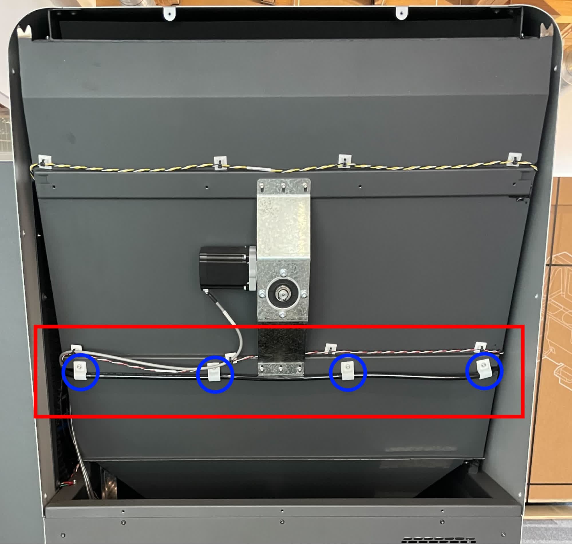
Step 6: Disconnect the chamber rinse tubing from the rear of the Fuse Blast
To remove the rear chamber rinse tubing, loosen the screws holding the tubing brackets in place using a T20 Torx driver.
Step 7: Reconnect the tubing
When you are done inspecting the tubes, push each back into its respective push-to-connect fitting. If you are replacing any of the tubes, install the replacement instead.
Inspecting or replacing the snorkel
Overview: Access the snorkel and its attachment points to the blasting chamber and filter cabinet to inspect or replace it.
Warning:
Air, media and powder all travel through the snorkel. Before removing the snorkel, empty as much media and powder from the catch chute as possible. Always wear appropriate PPE when inspecting any tubing that media or powder travels through. Use a compliant vacuum with static dissipative components, such as a Class II, Division 2 vacuum, for to clean up any spills from maintenance.
Step 1: Access the tubing
To access the snorkel, remove the left base panel.
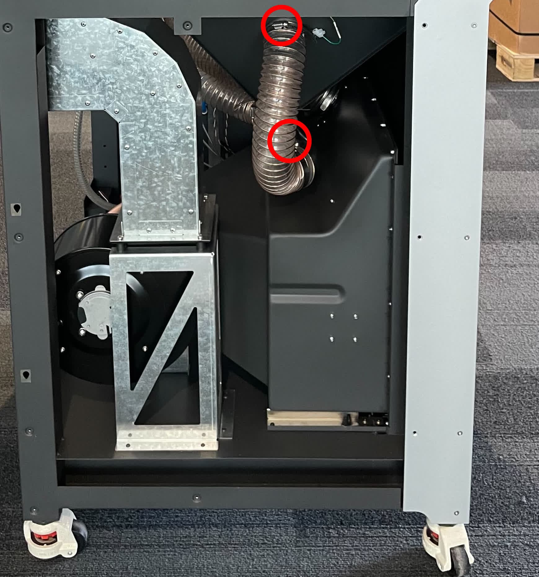
Step 2: Disconnect the snorkel
Using a slotted screwdriver, loosen the hose clamps from both ends of the snorkel. Pull the snorkel tube off of its flanges. If you are fully removing or replacing the snorkel, disconnect the ground cable or fully remove the hose clamp.
Step 3: Reconnect the snorkel
Slide both ends of the snorkel tube onto the flanges on the blasting chamber and filter cabinet. Use a slotted screwdriver to tighten the hose clamps. If you fully removed or replaced the snorkel, reconnect the ground cable as well.
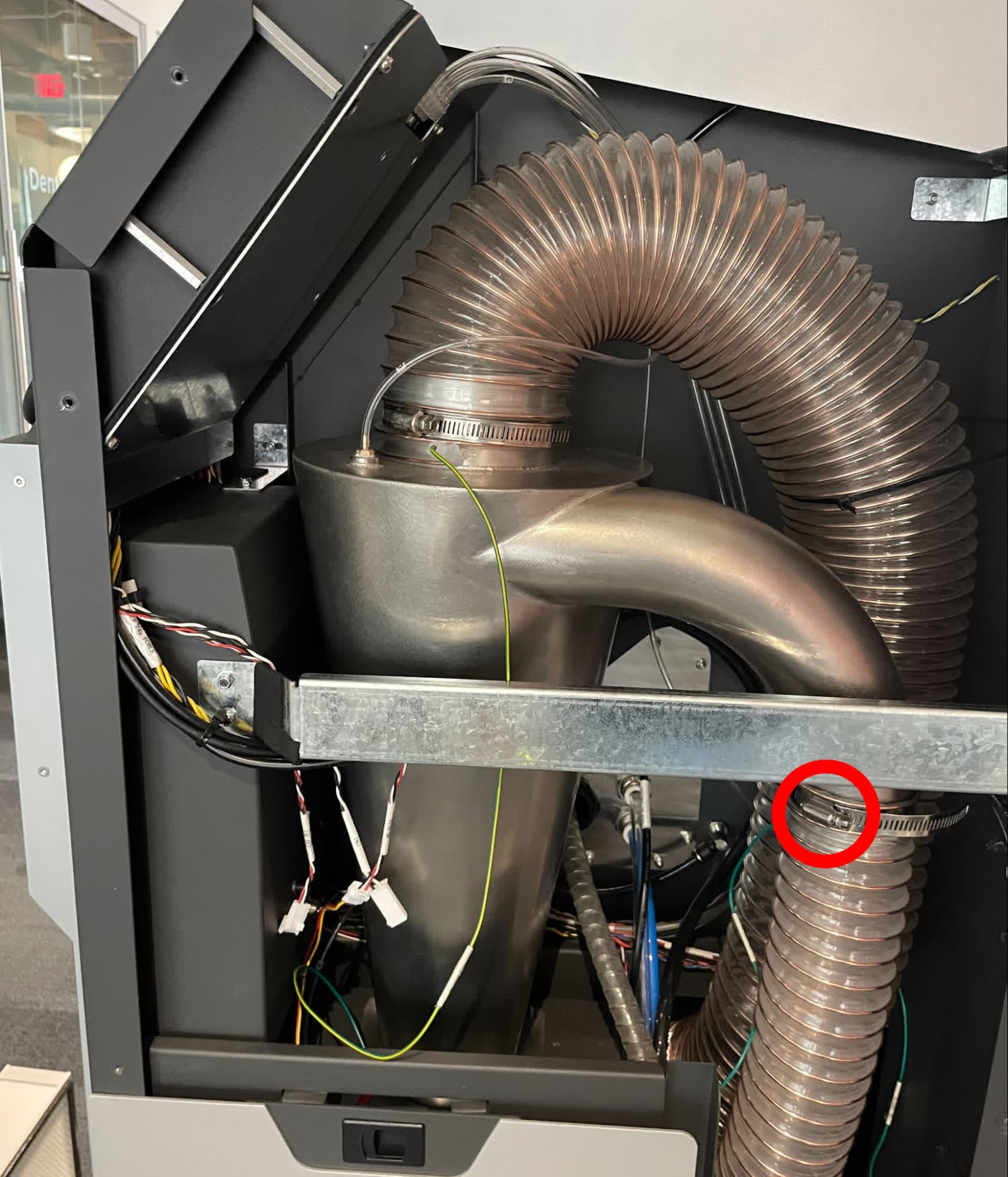
Inspecting or replacing the cyclone inlet tube
Overview: Access the cyclone inlet tube and its attachment points to the blasting chamber and the side of the cyclone separator to inspect or replace it.
Warning:
Air, media and powder all travel through the cyclone inlet tube. Before removing the cyclone inlet tube, empty as much media and powder from the catch chute as possible. Always wear appropriate PPE when inspecting any tubing that media or powder travels through. Use a compliant vacuum with static dissipative components, such as a Class II, Division 2 vacuum, for to clean up any spills from maintenance.
Step 1: Access the tubing
To access the cyclone inlet tube, remove the back base panel and the upper and lower sidecar panels.
Step 2: Disconnect the cyclone inlet tube
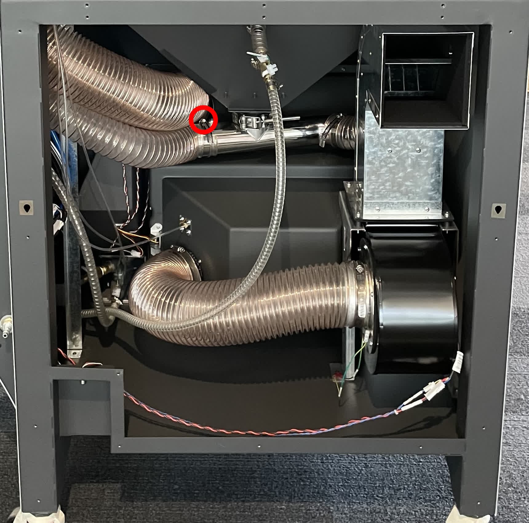
Using a slotted screwdriver, loosen the hose clamps from both ends of the cyclone inlet tube. Pull the cyclone inlet tube off of its flanges. If you are fully removing or replacing the cyclone inlet tube, disconnect the ground cable or fully remove the hose clamp.
Step 3: Reconnect the cyclone inlet tube
Slide both ends of the cyclone inlet tube tube onto the flanges on the blasting chamber and cyclone separator. Use a slotted screwdriver to tighten the hose clamps. If you fully removed or replaced the cyclone inlet tube, reconnect the ground cable as well.
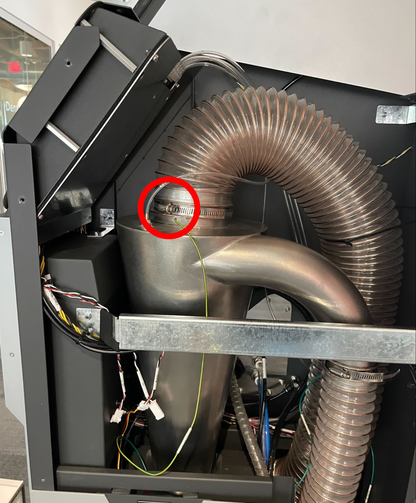
Inspecting or replacing the cyclone outlet tube
Overview: Access the cyclone outlet tube and its attachment points to the blasting chamber and the top of the cyclone separator to inspect or replace it.
Warning:
Air, media and powder all travel through the cyclone outlet tube. Before removing the cyclone outlet tube, empty as much media and powder from the catch chute as possible. Always wear appropriate PPE when inspecting any tubing that media or powder travels through. Use a compliant vacuum with static dissipative components, such as a Class II, Division 2 vacuum, for to clean up any spills from maintenance.
Step 1: Access the tubing
To access the cyclone outlet tube, remove the back base panel and the upper and lower sidecar panels. You may also need to remove the left base panel.
Step 2: Disconnect the cyclone outlet tube
Using a slotted screwdriver, loosen the hose clamps from both ends of the cyclone outlet tube. Pull the cyclone outlet tube off of its flanges. If you are fully removing or replacing the cyclone outlet tube, disconnect the ground cable or fully remove the hose clamp.
Step 3: Reconnect the cyclone outlet tube
Slide both ends of the cyclone outlet tube onto the flanges on the blasting chamber and cyclone separator. Use a slotted screwdriver to tighten the hose clamps. If you fully removed or replaced the cyclone outlet tube, reconnect the ground cable as well.
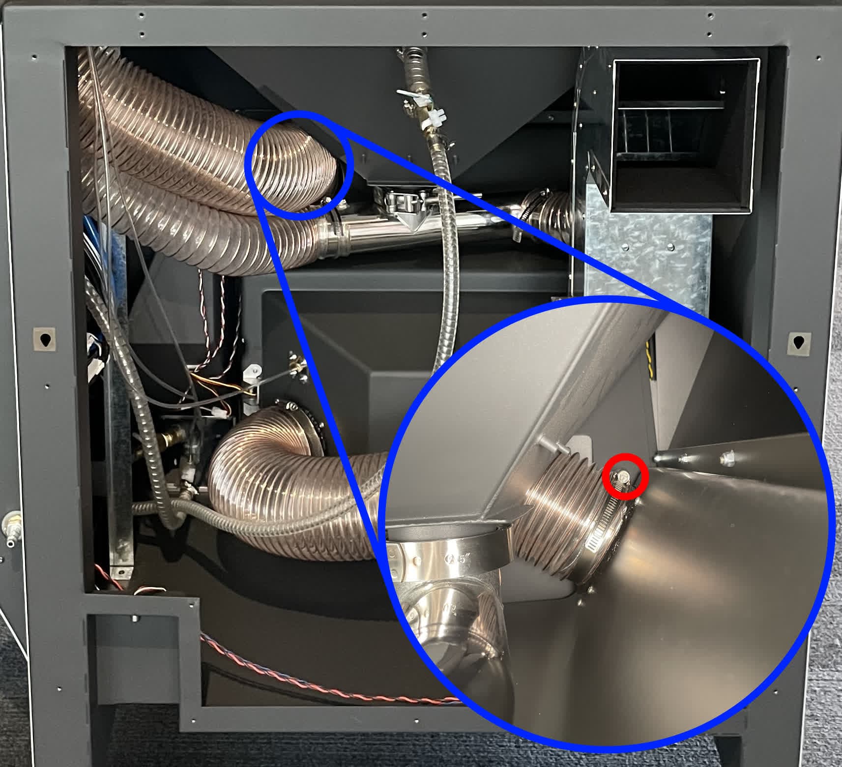
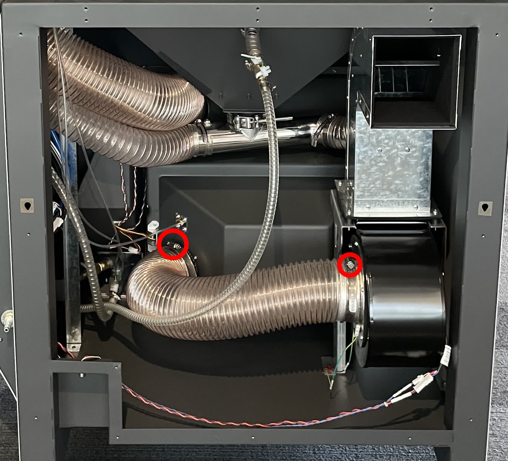
Inspecting or replacing the HEPA filter exhaust tube
Overview: Access the HEPA filter exhaust tube and its attachment points to the filter cabinet and blower fan to inspect or replace it.
Step 1: Access the tubing
To access the cyclone outlet tube, remove the back base panel.
Step 2: Disconnect the HEPA filter exhaust tube
Using a slotted screwdriver, loosen the hose clamps from both ends of the HEPA filter exhaust tube. Pull the tube off of its flanges on the side of the filter cabinet and the blower fan. If you are fully removing or replacing the HEPA filter exhaust tube, disconnect the ground cable or fully remove the hose clamp
Step 3: Reconnect the HEPA filter exhaust tube
Slide both ends of the HEPA filter exhaust tube onto the flanges on the filter cabinet and blower fan. Use a slotted screwdriver to tighten the hose clamps. If you fully removed or replaced the HEPA filter exhaust tube, reconnect the ground cable as well.
Inspecting or replacing the media suppy tube
Overview: Access the media suppy tube and its attachment points to the media hopper, blast gun, and blasting chamber to inspect or replace it.
Step 1: Access the tubing
To access the media supply tube, remove the back base panel as well as the upper and lower sidecar panels.
Step 2: Disconnect the media supply tube from the media hopper
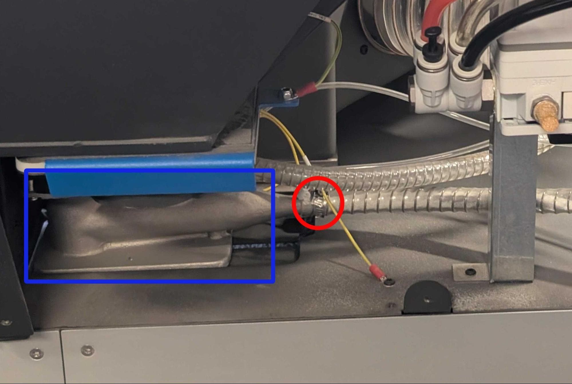
Using a slotted screwdriver, loosen the hose clamp from the rear of the media valve to release the media supply tube. If you are fully removing or replacing the media supply tube, disconnect the ground cable or fully remove the hose clamp.
Step 3: Disconnect the media supply tube from the blast gun
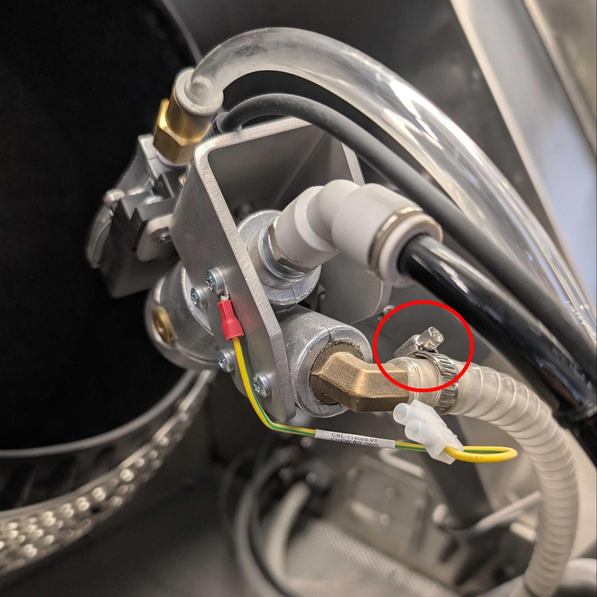
Inside the blasting chamber, use a slotted screwdriver to loosen the hose clamp securing the media supply tube to the blast gun.
Step 4: Disconnect the media supply tube from the blasting chamber
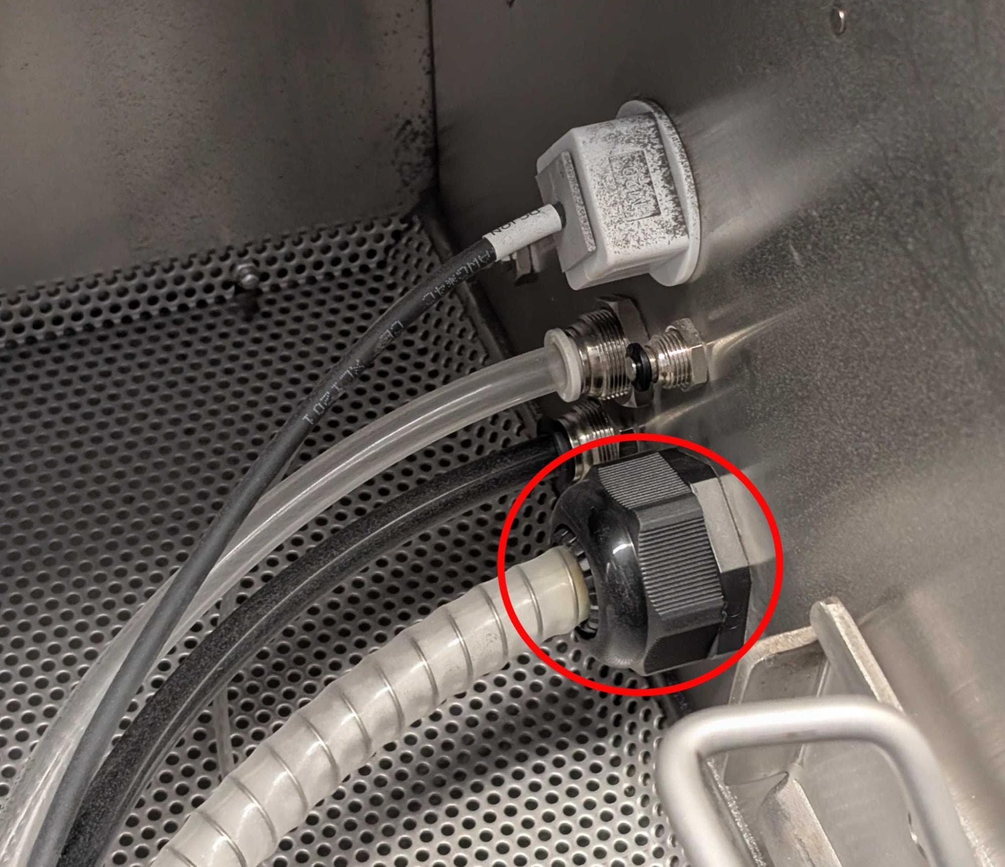
On the right side of the blasting chamber, loosen the hose gland securing the media supply tube.
Step 5: Reconnect the media supply tube
Slide the media supply tube onto its fittings on the media hopper and blast gun. Using a slotted screwdriver, tighten both hose clamps. Secure the hose gland to its fitting on the right side of the blasting chamber.
Inspecting or replacing the regurgitator line
Overview: Access the regurgitator line and its attachment points to the media valve and blasting chamber to inspect or replace it.
Step 1: Access the tubing
To access the regurgitator line, remove the back base panel as well as the upper and lower sidecar panels.
Step 2: Disconnect the regurgitator line from the media valve
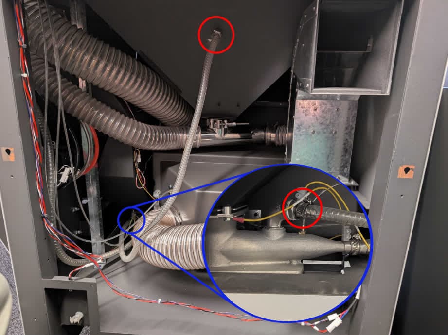
Using a slotted screwdriver, loosen the hose clamp from the top of the media valve to release the regurgitator line.
Step 3: Disconnect the regurgitator line from the blasting chamber
Using a slotted screwdriver, loosen the hose clamp from the rear of the blasting chamber to release the regurgitator line.
Step 4: Reconnect the regurgitator line
Slide the regurgitator line onto its fittings on the media valve and blasting chamber. Using a slotted screwdriver, tighten both hose clamps.
Inspecting or replacing the pressure tap tubes
Overview: Check the five pressure tap tubes and determine which one you are inspecting.
There are five pressure sensors in the Fuse Blast that are used to check for clogs or leaks in the system. These all run from the motherboard to the following positions, labeled 0–4 on both ends of the tubes:
Follow the section below for the pressure tap tube you are inspecting or replacing.
Inspecting or replacing the cyclone separator pressure tap tubing
Overview: Access the pressure tap tubing (position 0) to inspect or replace it.
Step 1: Access the tubing
To access the cyclone separator pressure tap tubing, remove the upper and lower sidecar panels.
Step 2: Inspect the tubing at the electronics box
Inspect the pressure tap tubing labeled 0 on the electronics box. If the tubing needs to be removed or replaced, pull it off the plastic fitting. If necessary, cut it at the fitting before replacing it.
Step 3: Inspect the tubing at the cyclone separator
Inspect the pressure tap tubing labeled 0 on the top of the cyclone separator. If the tubing needs to be removed or replaced, pull it off the brass fitting. If necessary, cut it at the fitting before replacing it.

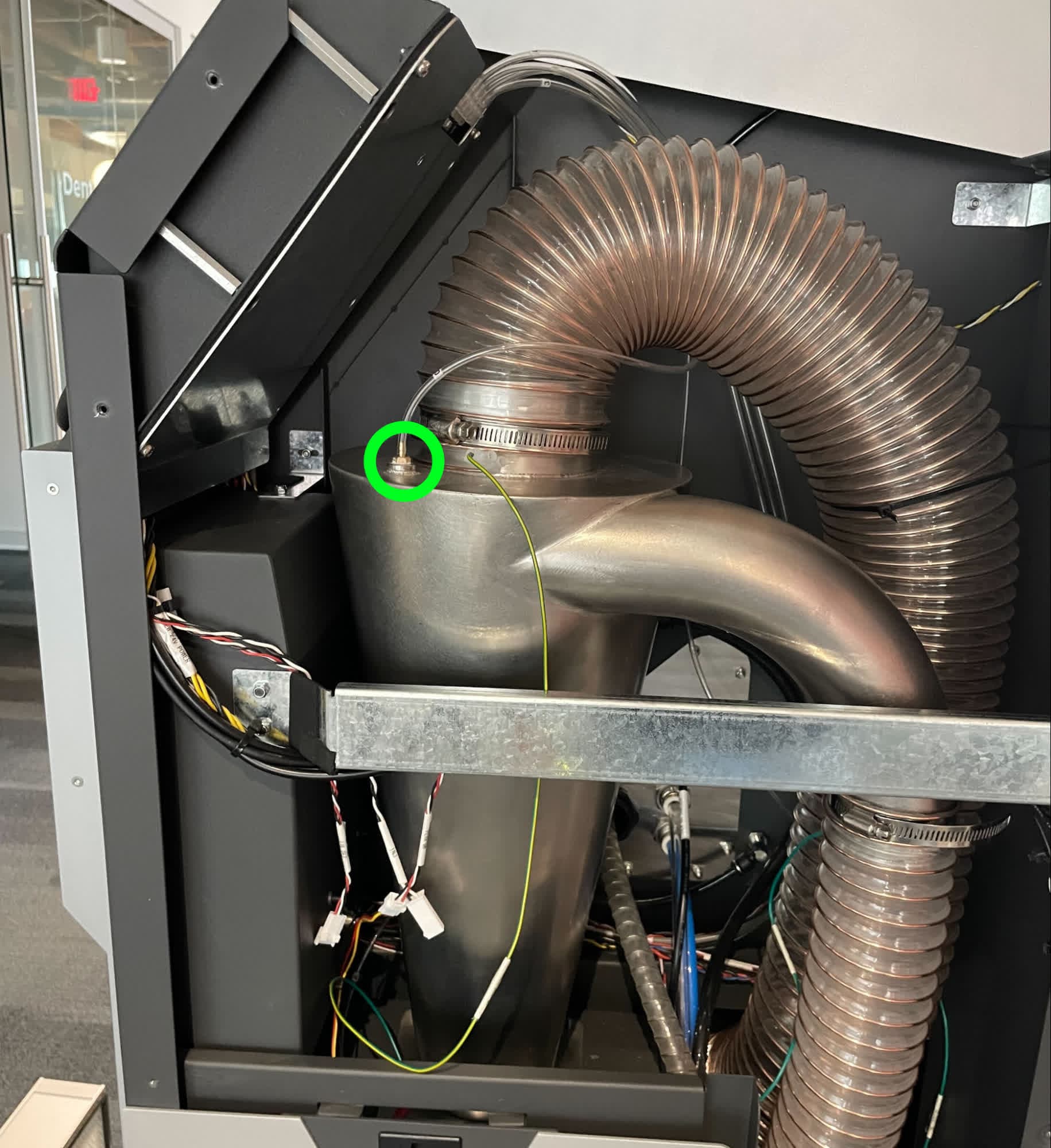
Step 4: Inspect the tubing within the electronics box
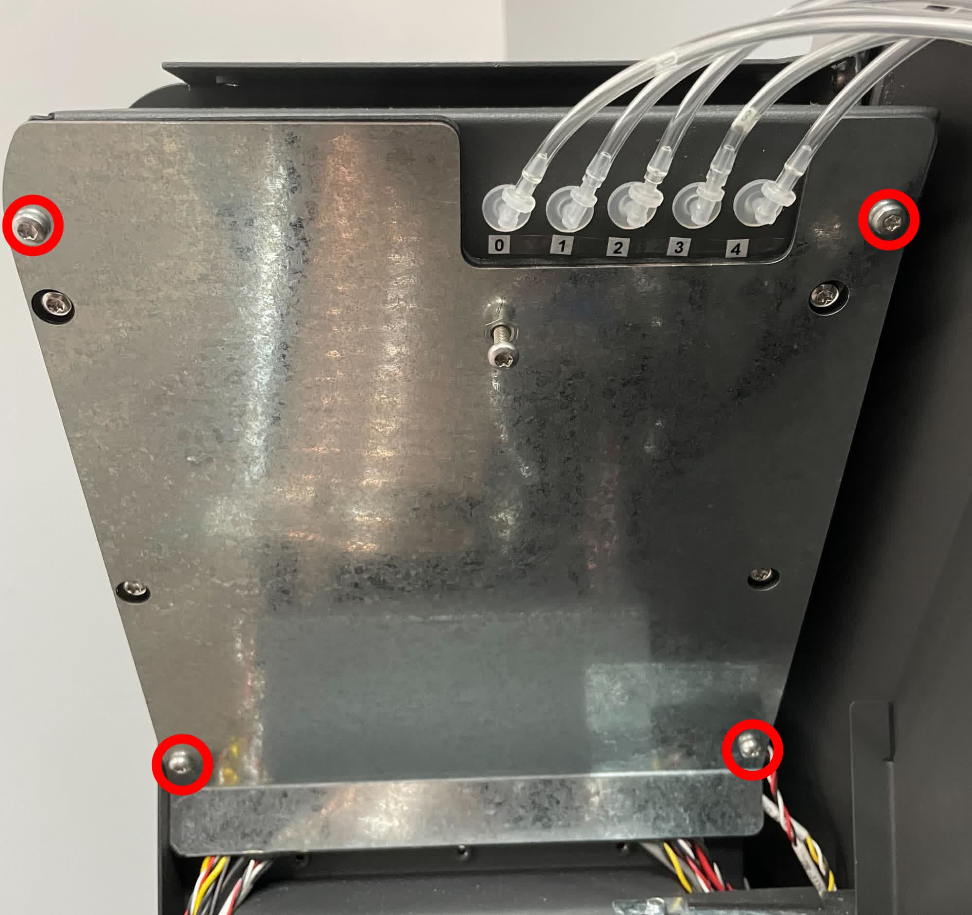
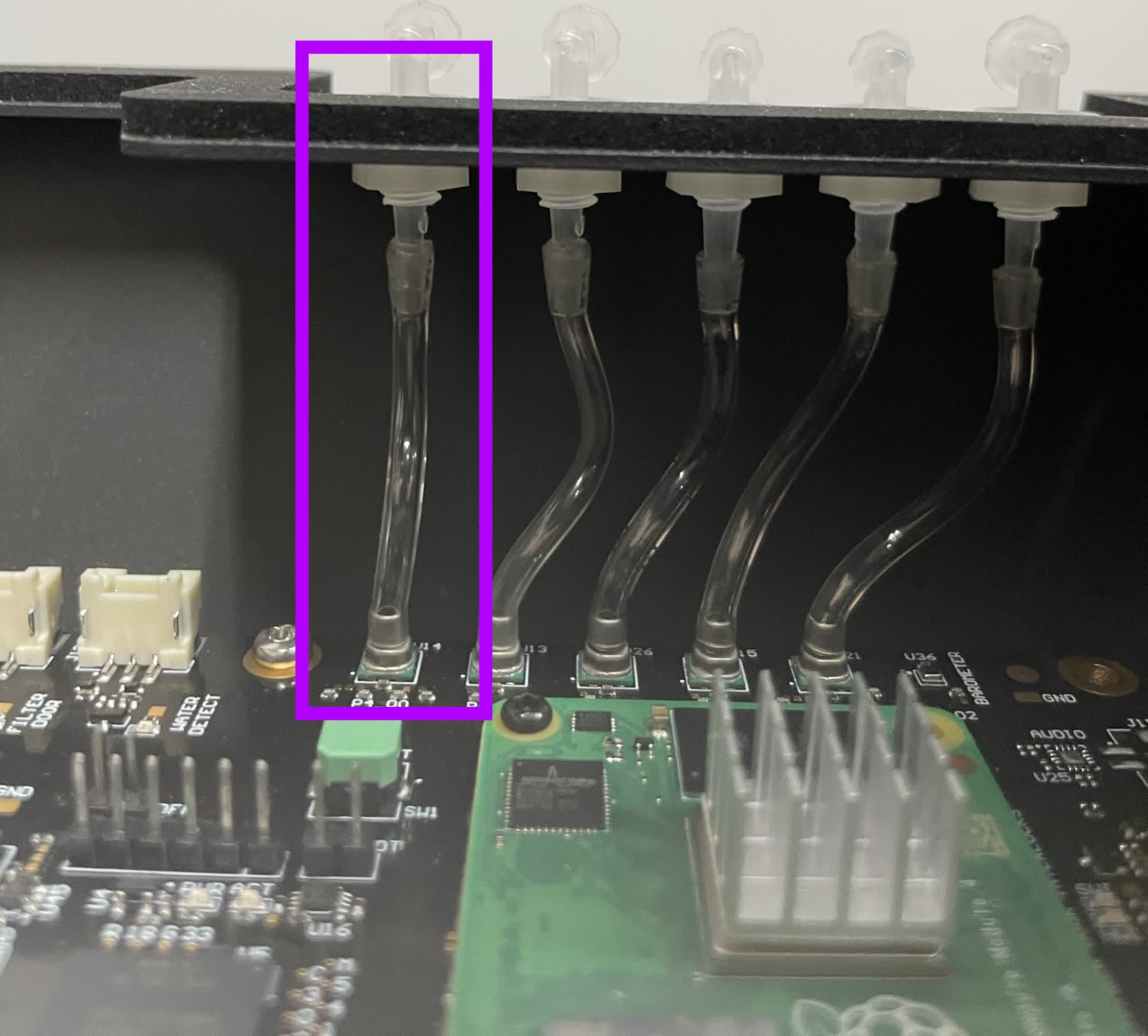
If necessary, remove the four T20 Torx screws securing the electronics box cover and inspect the internal electronics box pressure tube labeled 0. If the tubing needs to be removed or replaced, pull it off the fittings. If necessary, cut it at the fittings before replacing it.
The components in the electronics box are delicate. Take special care not to damage the motherboard, and ground yourself before handling electronics in the Fuse Blast.
Inspecting or replacing the media metering valve pressure tap tubing
Overview: Access the pressure tap tubing (position 1) to inspect or replace it.
Step 1: Access the tubing
To access the media metering valve pressure tap tubing, remove the back base panel and the upper and lower sidecar panels.
Step 2: Inspect the tubing at the electronics box
Inspect the pressure tap tubing labeled 1 on the electronics box. If the tubing needs to be removed or replaced, pull it off the plastic fitting. If necessary, cut it at the fitting before replacing it.
Step 3: Inspect the tubing at the media metering valve
Inspect the pressure tap tubing labeled 1 on the media metering valve, to the left of the filter box when facing the machine from the rear. If the tubing needs to be removed or replaced, pull it off the brass fitting. If necessary, cut it at the fitting before replacing it.
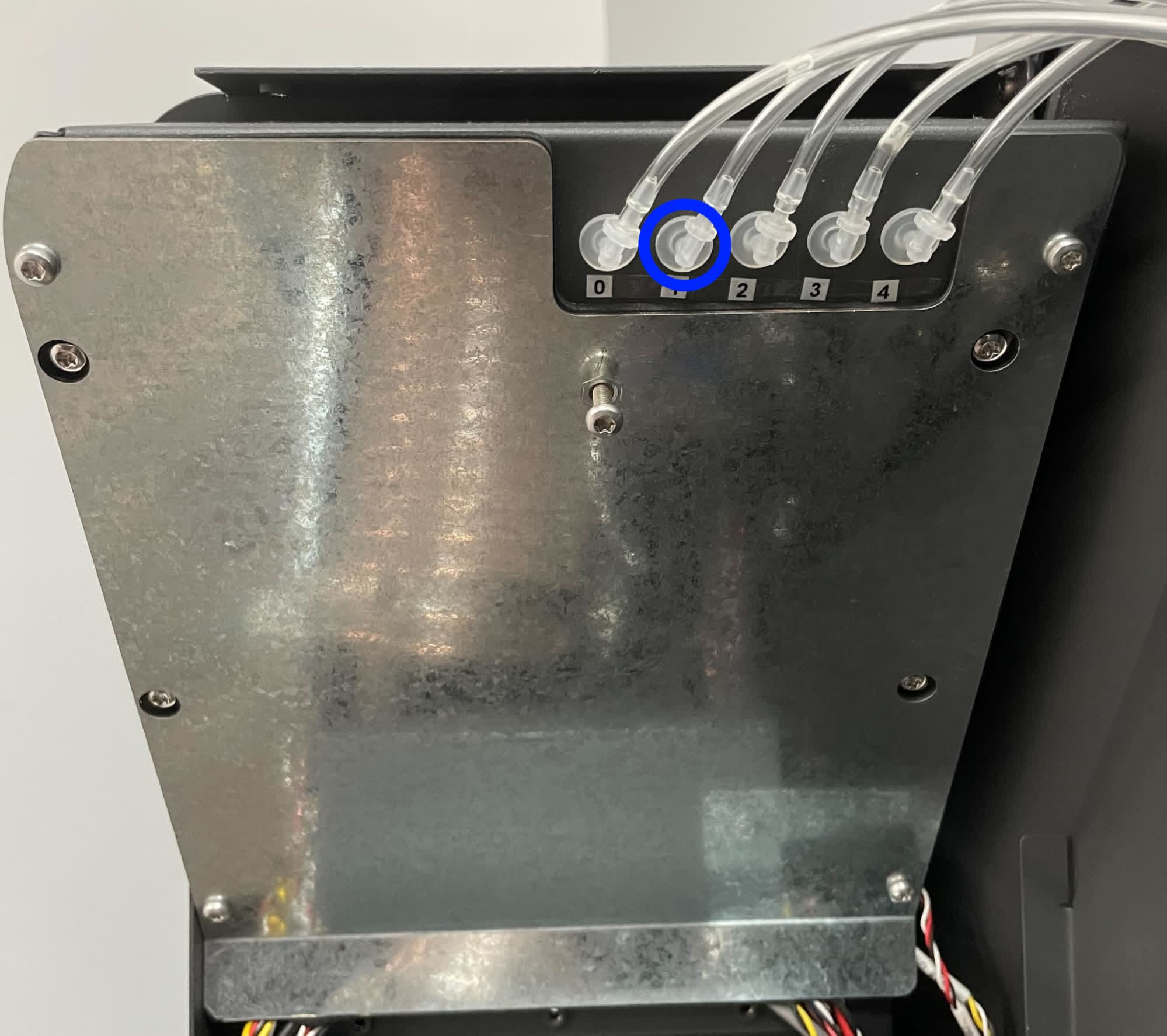
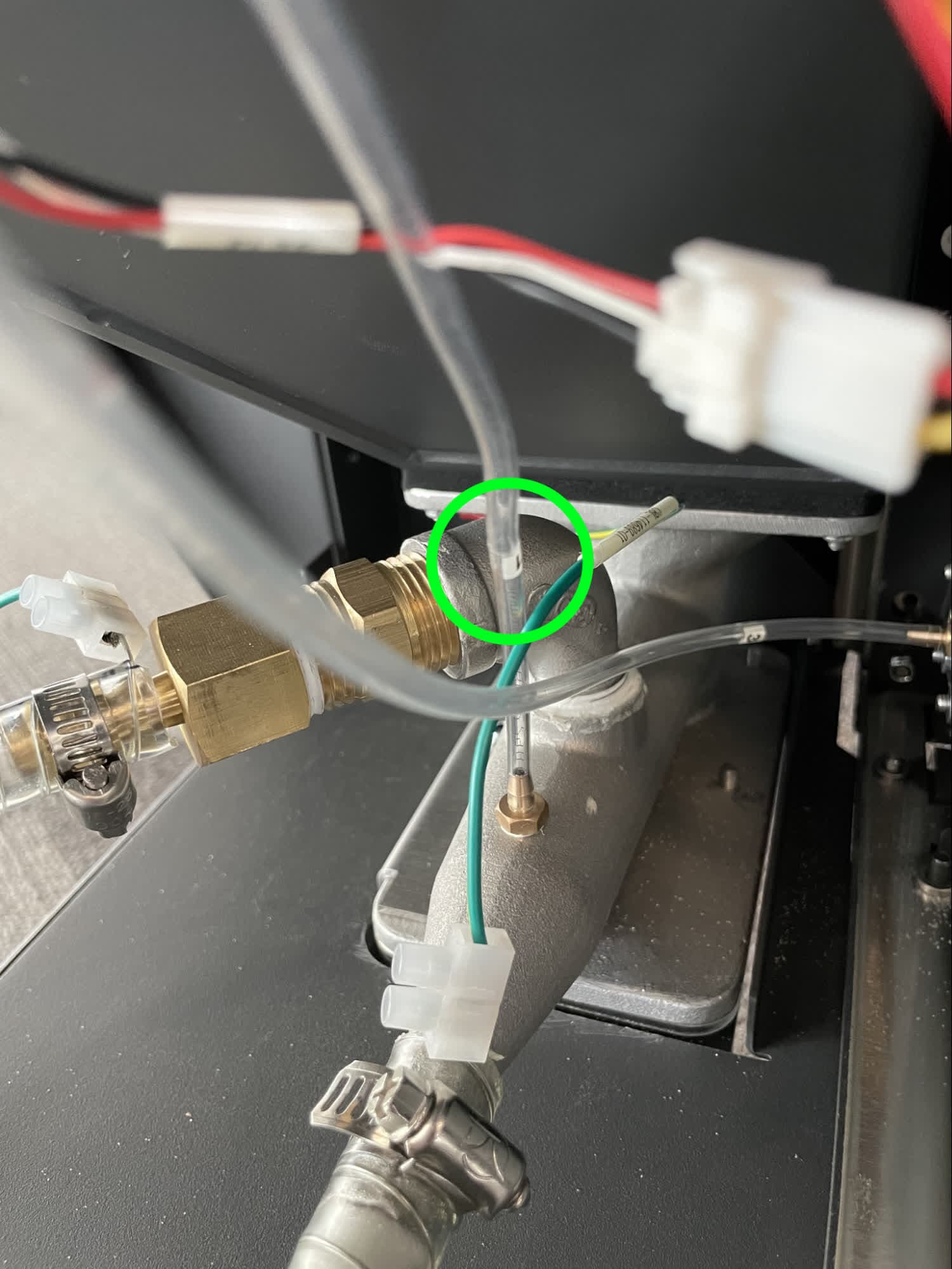
Step 4: Inspect the tubing within the electronics box
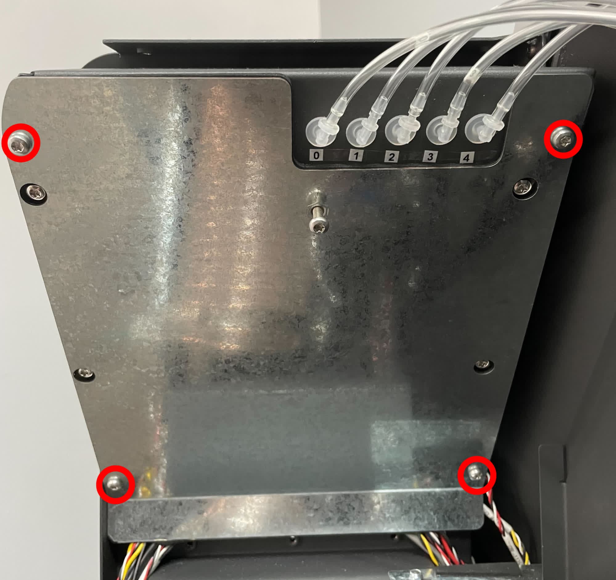
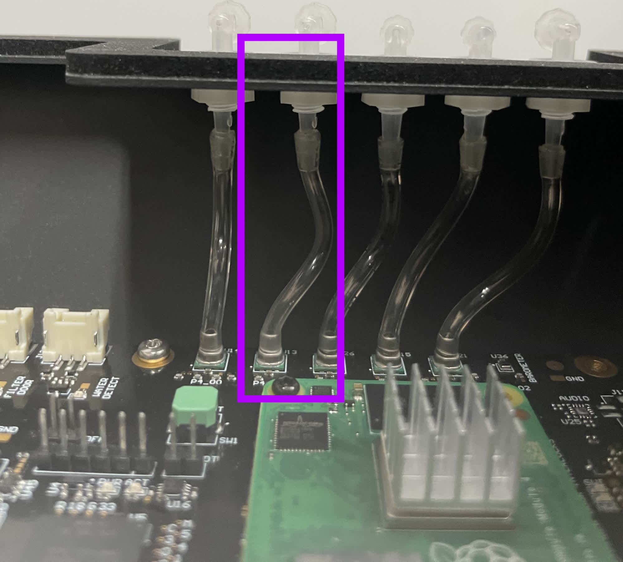
If necessary, remove the four T20 Torx screws securing the electronics box cover and inspect the internal electronics box pressure tube labeled 1. If the tubing needs to be removed or replaced, pull it off the fittings. If necessary, cut it at the fittings before replacing it.
The components in the electronics box are delicate. Take special care not to damage the motherboard, and ground yourself before handling electronics in the Fuse Blast.
Inspecting or replacing the post-air filter pressure tap tubing
Overview: Access the pressure tap tubing (position 2) to inspect or replace it.
Step 1: Access the tubing
To access the post-air filter pressure tap tubing, remove the back base panel and the upper and lower sidecar panels.
Step 2: Inspect the tubing at the electronics box
Inspect the pressure tap tubing labeled 2 on the electronics box. If the tubing needs to be removed or replaced, pull it off the plastic fitting. If necessary, cut it at the fitting before replacing it.
Step 3: Inspect the tubing at the filter cabinet
Inspect the pressure tap tubing labeled 2 at the top-left of the filter cabinet, when facing the machine from the rear. If the tubing needs to be removed or replaced, pull it off the brass fitting. If necessary, cut it at the fitting before replacing it.
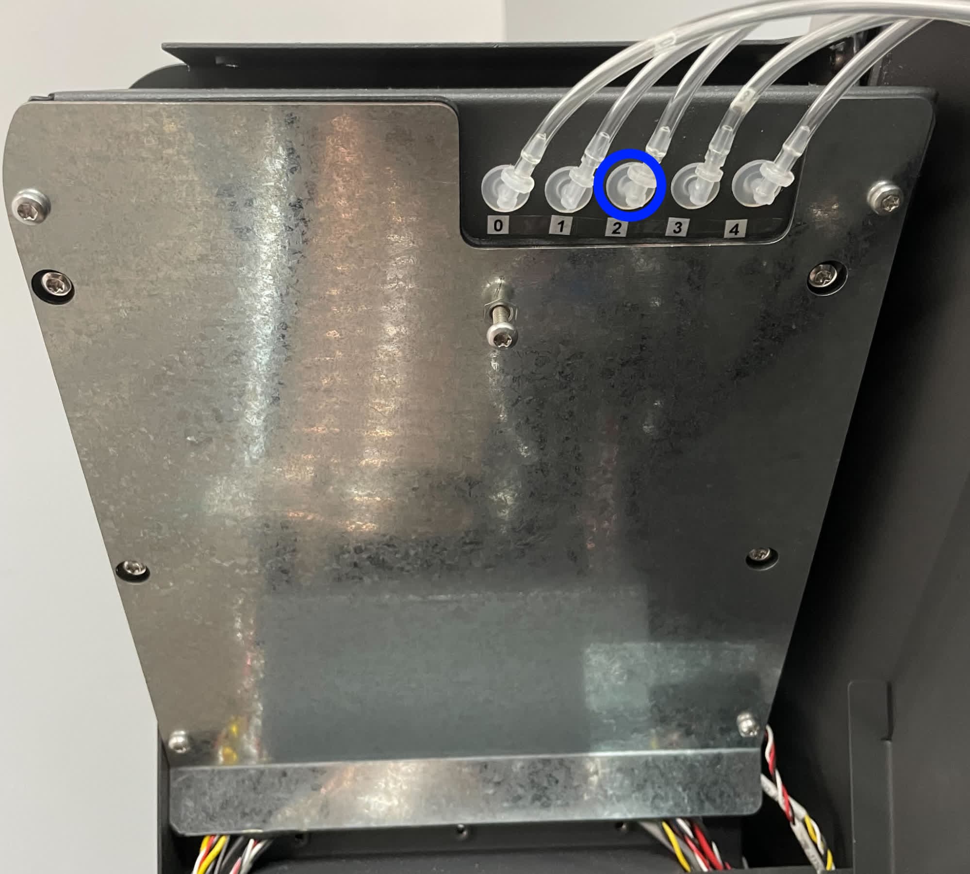
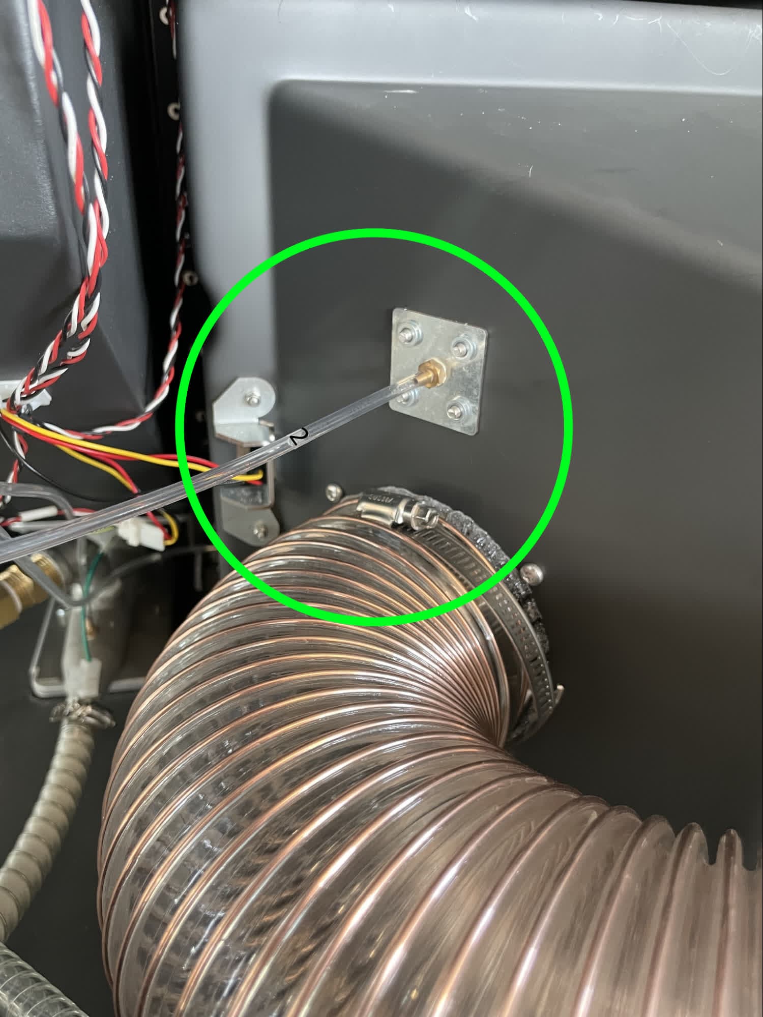
Step 4: Inspect the tubing within the electronics box
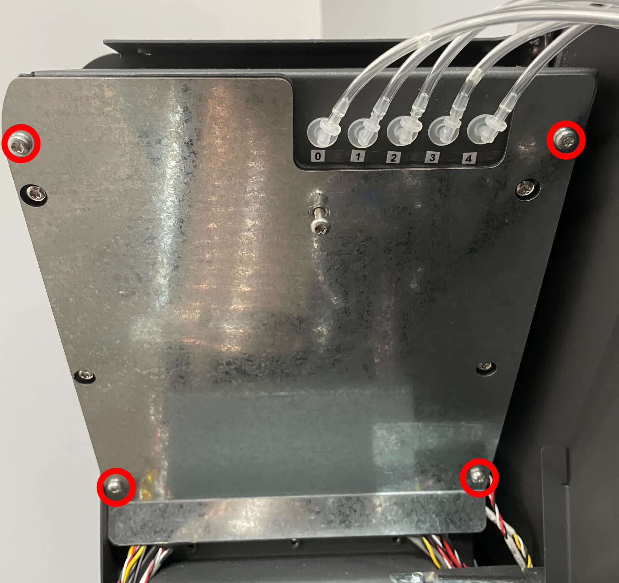
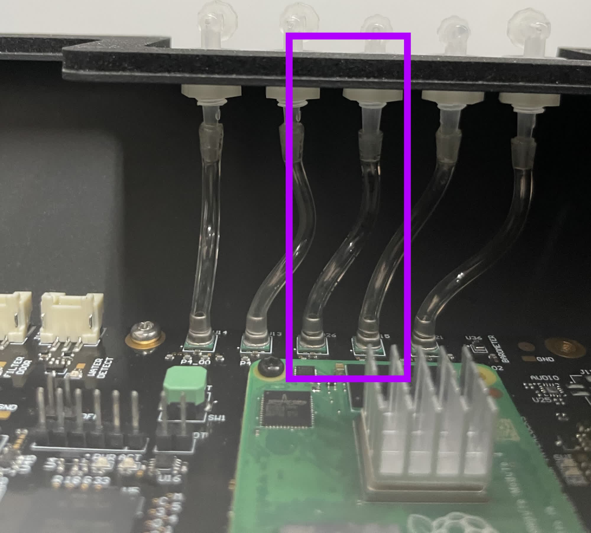
If necessary, remove the four T20 Torx screws securing the electronics box cover and inspect the internal electronics box pressure tube labeled 2. If the tubing needs to be removed or replaced, pull it off the fittings. If necessary, cut it at the fittings before replacing it.
The components in the electronics box are delicate. Take special care not to damage the motherboard, and ground yourself before handling electronics in the Fuse Blast.
Inspecting or replacing the pre-air filter pressure tap tubing
Overview: Access the pressure tap tubing (position 3) to inspect or replace it.
Step 1: Access the tubing
To access the pre-air filter pressure tap tubing, remove the back base panel and the upper and lower sidecar panels.
Step 2: Inspect the tubing at the electronics box
Inspect the pressure tap tubing labeled 3 on the electronics box. If the tubing needs to be removed or replaced, pull it off the plastic fitting. If necessary, cut it at the fitting before replacing it.
Step 3: Inspect the tubing at the filter cabinet
Inspect the pressure tap tubing labeled 3 at the bottom-left of the filter cabinet, when facing the machine from the rear. If the tubing needs to be removed or replaced, pull it off the brass fitting. If necessary, cut it at the fitting before replacing it.
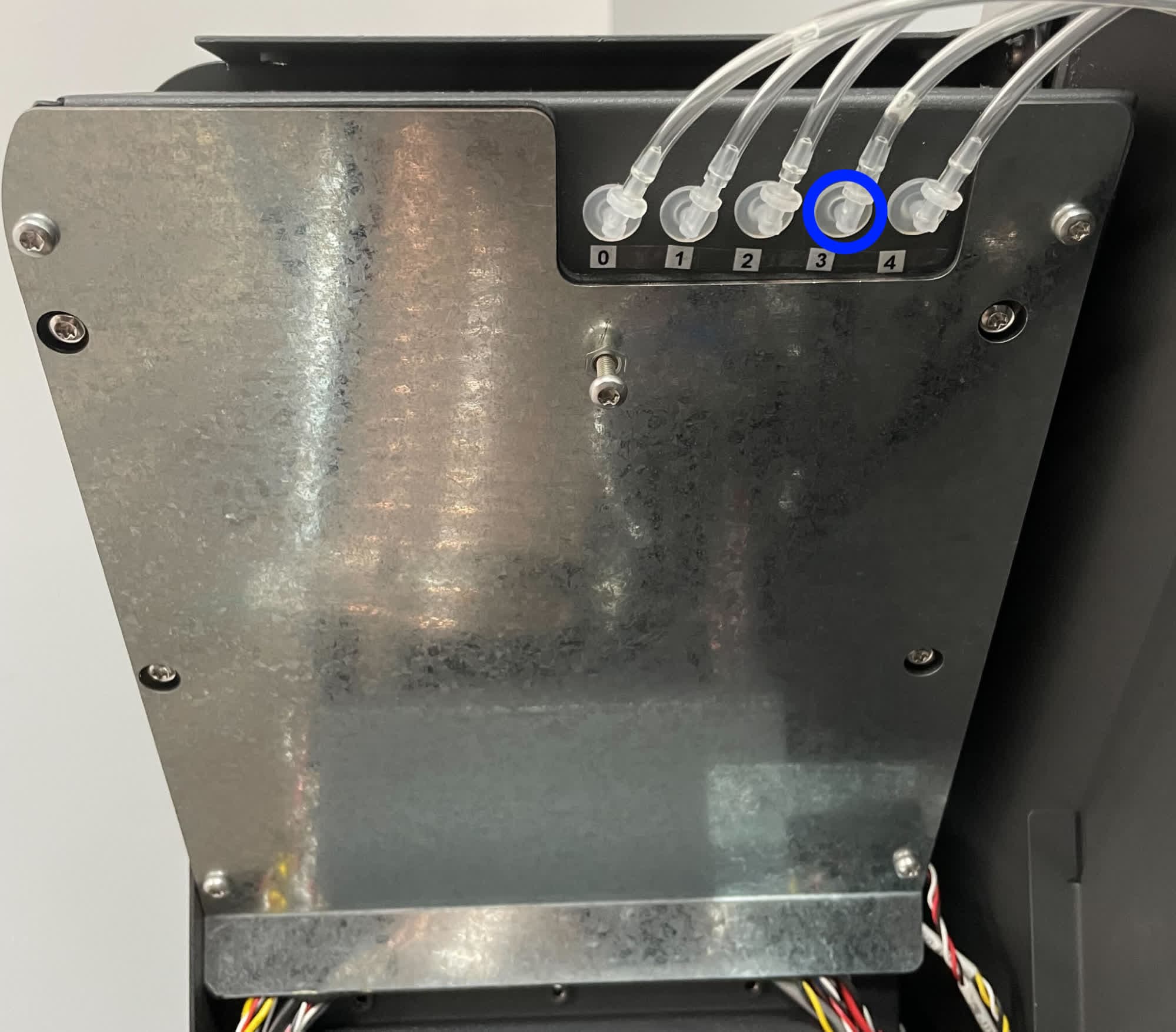
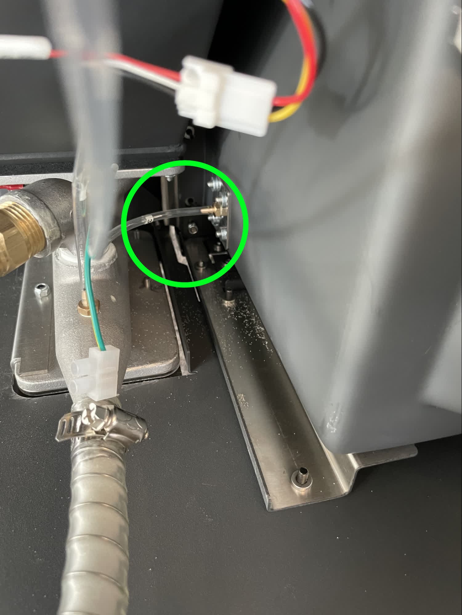
Step 4: Inspect the tubing within the electronics box
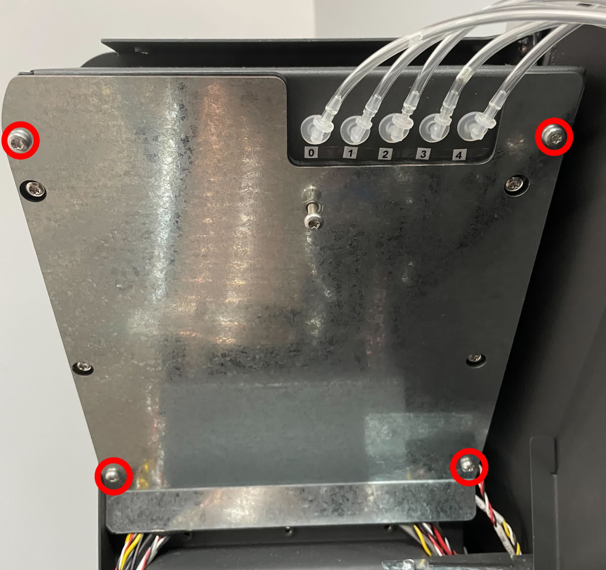
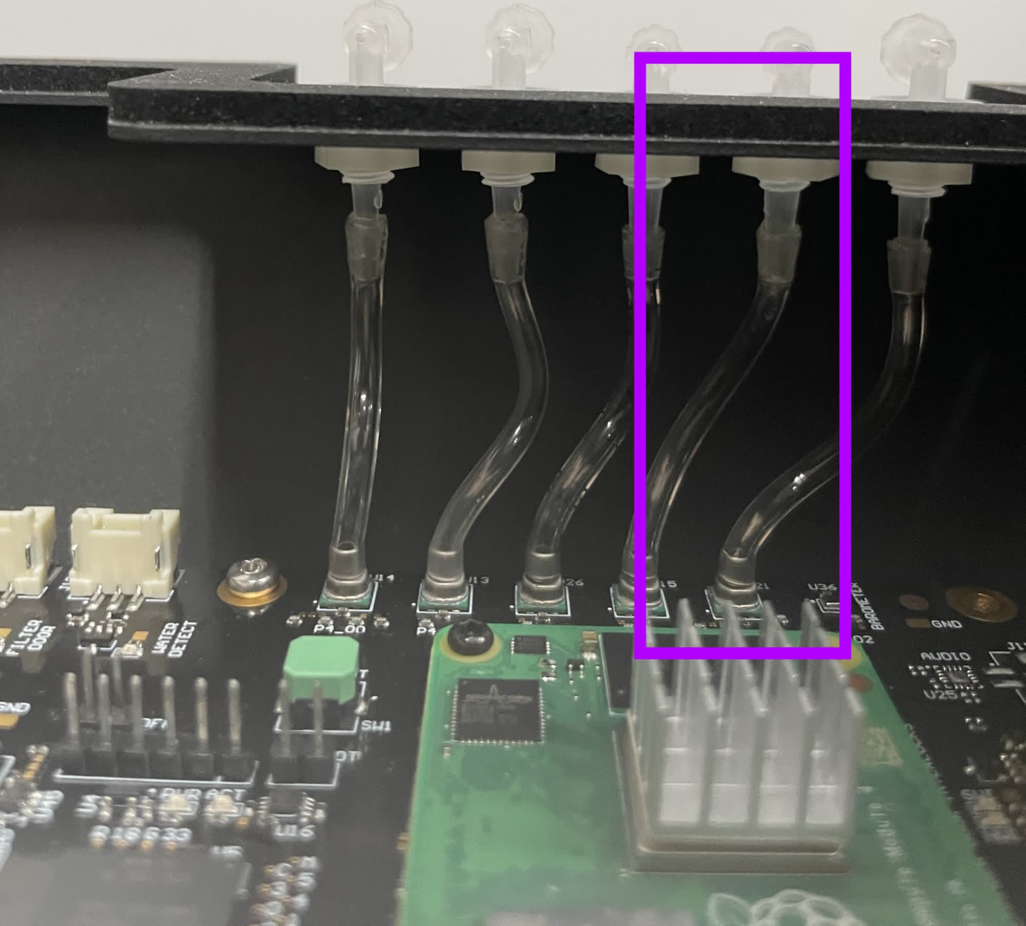
If necessary, remove the four T20 Torx screws securing the electronics box cover and inspect the internal electronics box pressure tube labeled 3. If the tubing needs to be removed or replaced, pull it off the fittings. If necessary, cut it at the fittings before replacing it.
The components in the electronics box are delicate. Take special care not to damage the motherboard, and ground yourself before handling electronics in the Fuse Blast.
Inspecting or replacing the waste hopper pressure tap tubing
Overview: Access the pressure tap tubing (position 4) to inspect or replace it.
Step 1: Access the tubing
To access the waste hopper pressure tap tubing, remove the upper and lower sidecar panels.
Step 2: Inspect the tubing at the electronics box
Inspect the pressure tap tubing labeled 4 on the electronics box. If the tubing needs to be removed or replaced, pull it off the plastic fitting. If necessary, cut it at the fitting before replacing it.
Step 3: Inspect the tubing at the waste hopper
Inspect the pressure tap tubing labeled 4 above the waste hopper, to the left of the cyclone separator. If the tubing needs to be removed or replaced, pull it off the brass fitting. If necessary, cut it at the fitting before replacing it.
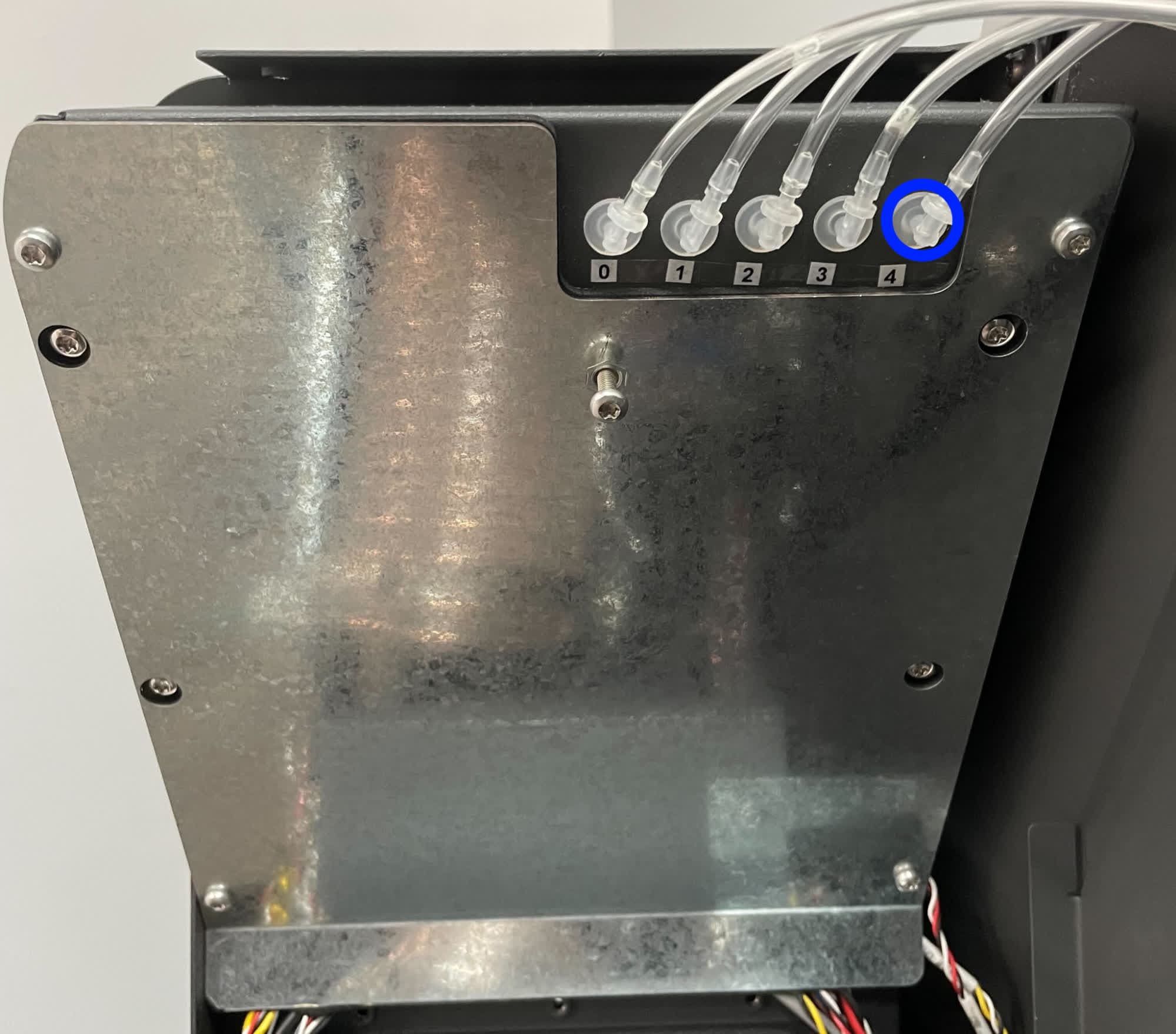
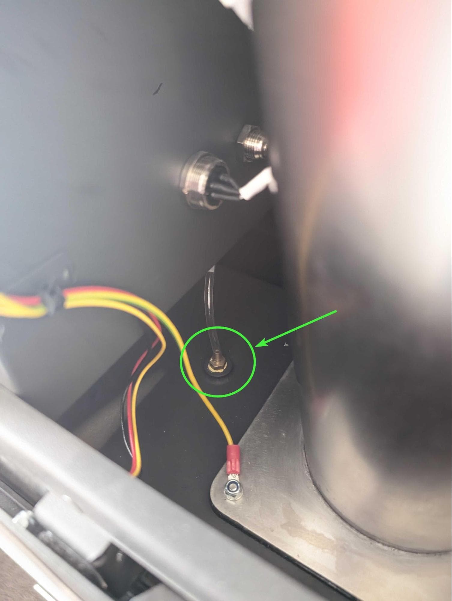
Step 4: Inspect the tubing within the electronics box
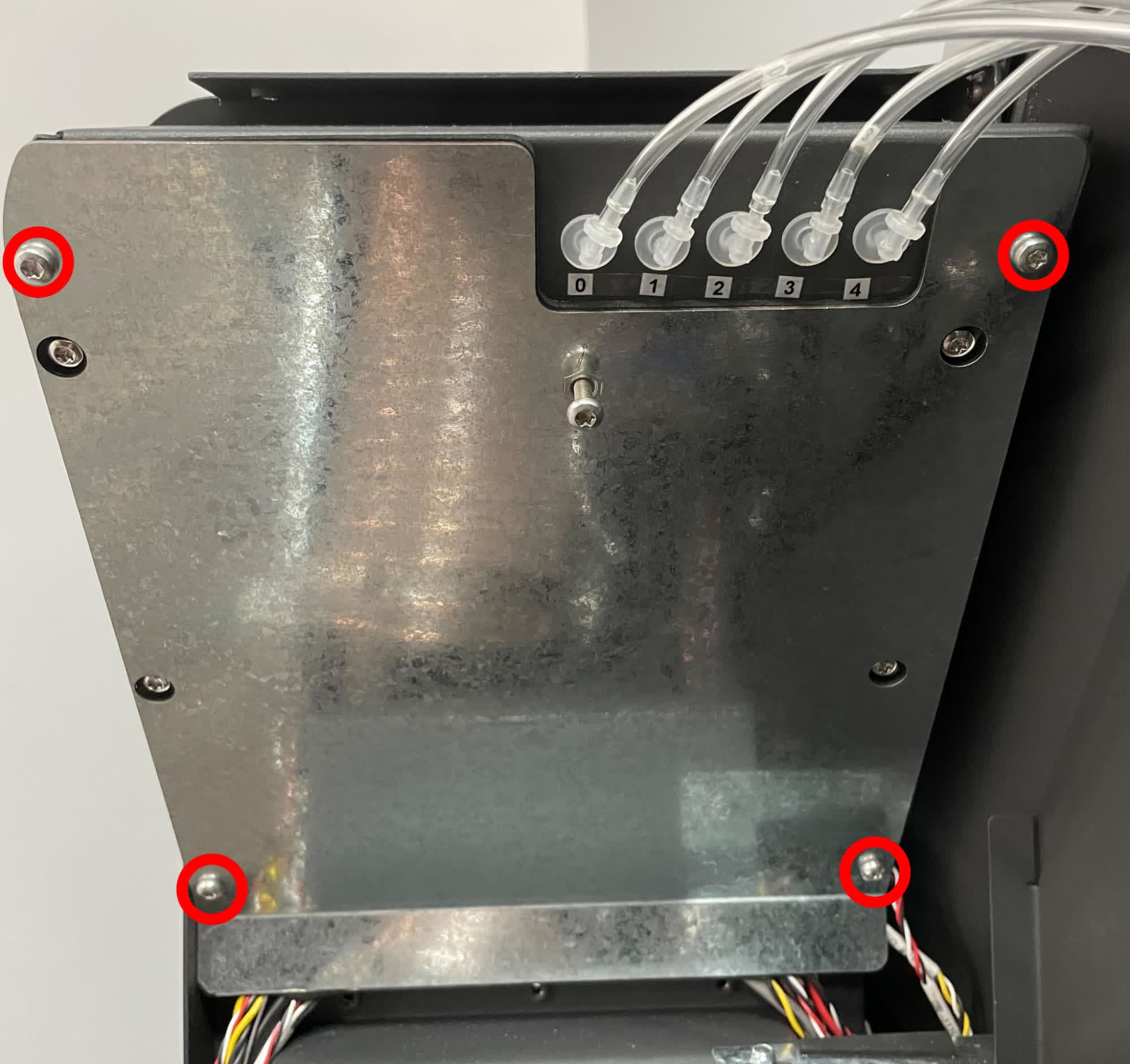
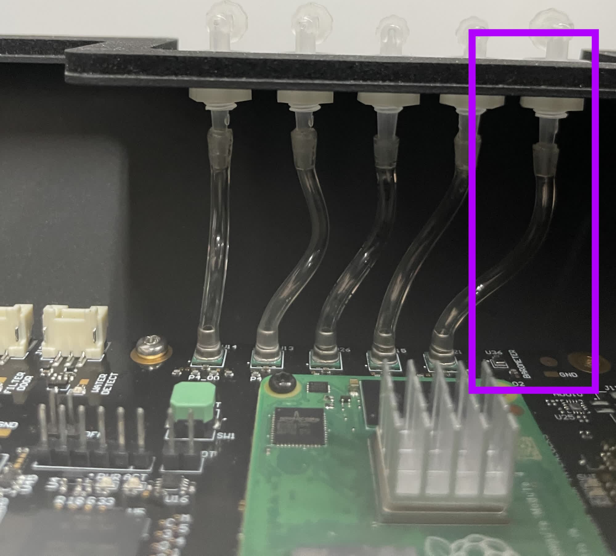
If necessary, remove the four T20 Torx screws securing the electronics box cover and inspect the internal electronics box pressure tube labeled 4. If the tubing needs to be removed or replaced, pull it off the fittings. If necessary, cut it at the fittings before replacing it.
The components in the electronics box are delicate. Take special care not to damage the motherboard, and ground yourself before handling electronics in the Fuse Blast.
Finalizing the repair
Overview: After replacing the blower fan, power on the machine and perform final checks.
Step 1: Reinstall machine panels
Mount and secure any panels you removed to inspect or replace tubing.
Step 2: Power on the machine
Connect the power cable to the machine and the power supply. Flip the power switch on the back of the machine to the ON position. The machine initializes.
Step 3: Test the repair
Reconnect the compressed air source if you previously disconnected it. Test the various functions of the machine to ensure that it operates normally and does not make any unusual sounds.