
Tip:
Visit the Form 3 interactive tour for a 3D view of many of the components detailed below.

Tip:
Visit the Form 3 interactive tour for a 3D view of many of the components detailed below.
External components
| Item | Description | Image |
|---|---|---|
| Shell | Five protective external casings protect the printer’s internal components:
|  |
| Leveling feet | Each corner of the printer is supported by a rubber foot that is threaded into the bottom of the machine. When prompted by the touchscreen, use the leveling disc to raise or lower each foot to ensure that the printer is acceptably level. |  |
Display assembly
| Item | Description | Image |
|---|---|---|
| Display assembly | The display assembly contains the touchscreen and the display circuit board. A ribbon cable connects the display assembly to the motherboard. |  |
| Touchscreen | The LCD capacitive touch user interface displays print information, settings, and error messages. |  |
| Display PCB | This circuit board, separated from the main motherboard, controls the touchscreen. |  |
| Display cable | A flat, flexible cable connects the display assembly to the motherboard. |  |
Cover
| Item | Description | Image |
|---|---|---|
| Cover | The upper enclosure, made of strong, amber-tinted material, blocks exposure to the laser and protects the resin from curing due to ambient light. |  |
| Interlock magnets | The interlock sensor detects these magnets to determine when the cover is closed. This safety mechanism triggers the Cover is open message on the touchscreen and disables the laser when the cover is open. |  |
Cartridge
| Item | Description | Image |
|---|---|---|
| Cartridge | This container holds the resin before dispensing into the resin tank. Shake the cartridge periodically to keep resin well mixed. |  |
| Vent cap | The lid at the top of the cartridge allows for air interchange, enabling proper resin dispensing. Push the vent cap open prior to printing. |  |
| Cartridge ID chip | An Electrically Erasable Programmable Read-Only Memory (EEPROM) chip is attached to the cartridge skirt and is programmed with the resin type. This chip communicates to the printer via spring fingers on the cartridge floor. |  |
| Bite valve | This flexible seal regulates resin dispensing. Resin flows out when the cartridge dispense arm squeezes the valve open. |  |
Cartridge floor assembly
| Item | Description | Image |
|---|---|---|
| Cartridge spring fingers | Two electrical contacts comprise the spring fingers located on the cartridge floor. The physical contact establishes an electrical connection with the cartridge ID chip to detect the cartridge. |  |
| Cartridge dispense arm | This plastic hook presses against the bite valve to dispense resin out of the cartridge into the resin tank. |  |
Z-axis
| Item | Description | Image |
|---|---|---|
| Z-tower | This vertical tower at the back of the printer provides support for many parts of the Form 3/Form 3B. The build platform is raised and lowered along the Z-axis, inside the tower. The Z-tower also encloses the resin cartridge, the heater, and the mechanisms for dispensing the resin into the tank. | 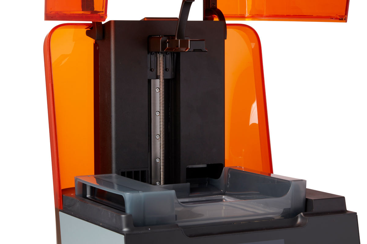 |
| Z-axis lead screw | The Z-axis lead screw controls the vertical motion of the build platform carriage. |  |
| Limit switch board | A single board connects to two optical sensors to detect when the build platform carriage reaches the top of the tower and when the build platform is installed. |  |
| Heater | The resin in the resin tank is heated by hot air blown out of the tower behind the resin tank. The warm air in the print chamber heats the resin, and the air temperature is sensed by a thermal sensor at the air intake. |  |
| Fans | A heating fan blows air across the heater into the resin tank. |  |
Build platform
| Item | Description | Image |
|---|---|---|
| Build platform | The aluminum base provides a surface for prints to attach to. |  |
| Platform lock | This lever is part of the locking mechanism that secures the build platform. |  |
| Build platform carriage | The carriage is the metal arm that the build platform slides onto. |  |
| Build platform sensor | Inserting the build platform triggers a limit switch in the Z-axis. The printer detects when the build platform is properly installed in its home position. | 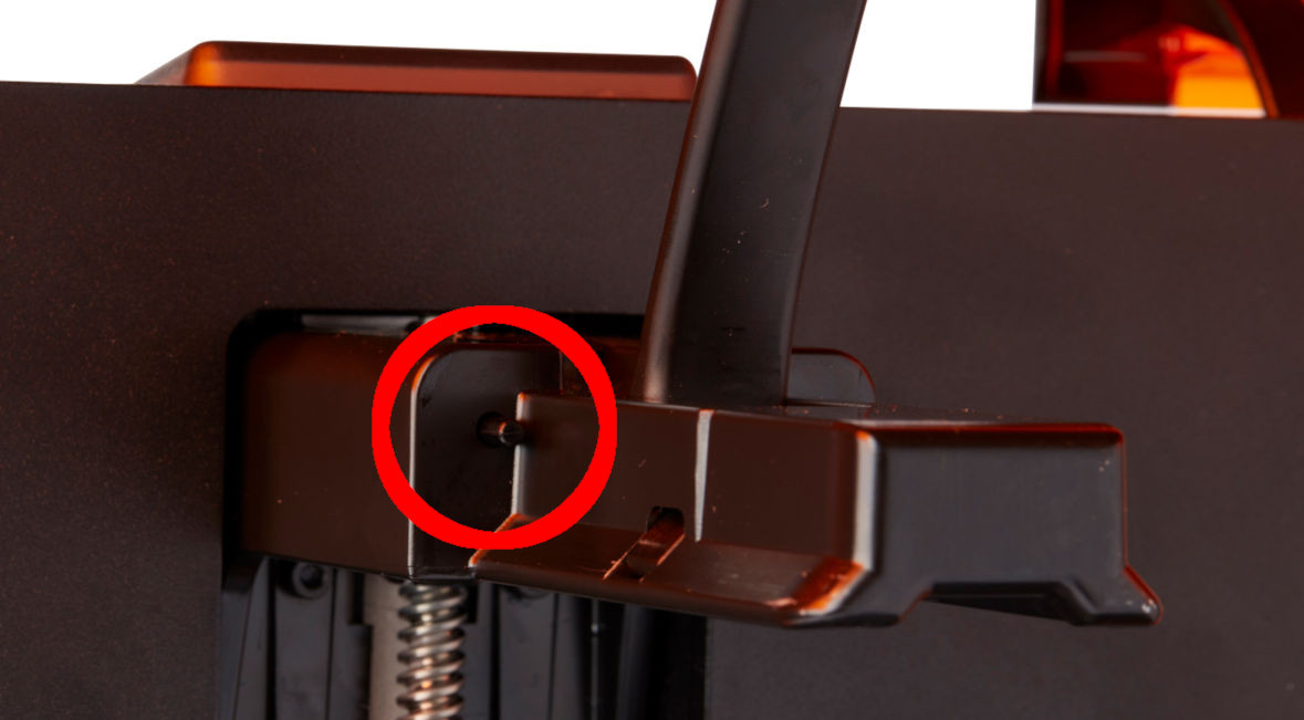 |
| Platform lock spring | The spring mechanism inside the build platform carriage allows the platform lock to move up and down. It also mechanically locks and unlocks the build platform. |  |
| Platform lock set screws | These three screws are used for adjusting the tension in the platform lock. Contact Formlabs Support before adjusting these screws, as improper adjustment can lead to damage to the machine. |  |
Resin tank
| Item | Description | Image |
|---|---|---|
| Resin tank | The resin tank is the primary container for holding resin after it is dispensed from the cartridge. Resin is cured onto the build platform when the laser passes through the tank’s bottom film. Only use approved materials and processes to clean the resin tank and film. |  |
| Tank handles | Plastic handles on each side of the resin tank allow for easy insertion, removal, and carrying of the tank. Avoid touching the bottom of the resin tank, as fingerprints can leave smudges that obstruct the optical path. |  |
| Tank spout | This spout at the back of the resin tank sits underneath the cartridge dispense hole and receives resin from the cartridge. |  |
| Film | A durable, dual-layer film comprises the bottom surface of the resin tank. Parts print in the resin-filled gap between the film and the build platform. The quality of printed parts depends on the film being clean and clear of damage and debris. |  |
| Resin tank ID chip | The resin tank's ID chip uses Electrically Erasable Programmable Read-Only Memory (EEPROM). The tank spring fingers read the chip to detect the unique tank ID and current resin type. |  |
| Mixer | Each resin tank includes a mixer that improves print consistency by clearing the build area and circulating the resin. The mixer attached to the roller holder with magnetic coupling and rests under the mixer case when not in use. Scrapers on the top and bottom of the mixer clear the build platform and film, respectively. |  |
| Mixer case | When not in use, the mixer rests in a partially enclosed compartment on the left side of the resin tank. The float is permanently attached inside the mixer case. |  |
| Float | A hinged bobber rests on the surface of the resin. The aluminum counterweight passes in front of the LevelSense board to determine the amount of resin in the tank. | 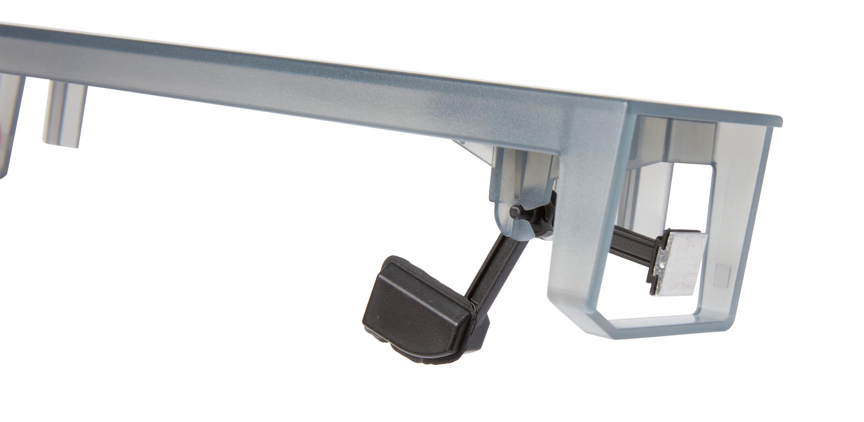 |
| Tank case | Each resin tank includes a lidded container for storing the resin tank when not in use. For newer resin tanks, the shipping box also acts as the tank case. |  |
| Tank tool | Inspecting and cleaning the interior of the resin tank requires a special two-part spatula. This is the only tool to clean the interior film surface. |  |
Tank carrier
| Item | Description | Image |
|---|---|---|
| Tank carrier | This assembly holds the resin tank and tensions the film. The tank carrier is covered by the top shell and houses the film tensioner, LevelSense, resin tank spring fingers, tank catch flexures, and interlock sensors. |  |
| Tank carrier rails | The resin tank side walls connect to linear slots on each side of the tank carrier. While printing, the rails pull the tank walls and the film into tension. |  |
| Film tensioner | A motor pulls outward on the tank side walls to create a taut film surface in the resin tank. |  |
| Tank spring fingers | These electrical contacts, at the back of the resin tank carrier, read the resin tank’s EEPROM ID chip to sense the tank’s presence and to communicate the resin type to PreForm. |  |
Motherboard
| Item | Description | Image |
|---|---|---|
| Motherboard | The motherboard is the main circuitry through which all systems in the printer communicate. |  |
| Power supply | The Form 3/Form 3B utilizes a 100–240 V power supply. The internal power supply converts line power to +24V DC. |  |
| Front display connector | This connector links the display to the motherboard via a ribbon cable. |  |
| Wi-Fi antenna | The Wi-Fi antenna enables the Form 3/Form 3B's wireless connectivity. The antenna is connected to the printer's motherboard. |  |
| Ethernet port | The Form 3/Form 3B can connect to a network via Ethernet. The port is connected to the motherboard and can be accessed from the back of the machine. |  |
| USB port | The Form 3/Form 3B can connect to a computer via USB. The port is connected to the motherboard and can be accessed from the back of the machine. |  |
| Fans | Cooling fans pull warm air away from electronic components. |  |
LevelSense
| Item | Description | Image |
|---|---|---|
| LevelSense board | Two inductive coils determine the amount of resin in the tank by detecting the relative height of the float. |  |
Optics
| Item | Description | Image |
|---|---|---|
| Light Processing Unit (LPU) | This interchangeable assembly contains the laser and the mirrors the control the path of the laser, ensuring a clean, crisp laser spot. The LPU is secured in the right-hand side of the LPU housing. |  |
| Laser | The laser is the source of curing energy in the Form 3/Form 3B. It has a 405 nm violet diode and a maximum output of 250 mW. The Form 3/Form 3B is a Class 1 laser product. |  |
| Light Processing Unit (LPU) cable | A flat, flexible cable connects the LPU to the motherboard. |  |
| Light Processing Unit (LPU) housing | The aluminum housing for the optics engine moves left and right, traveling along the X-axis lead screw. The LPU, roller holder, and mixer are all controlled within the LPU housing. |  |
| Roller holder | Segmented metal rods (rollers) act as a sliding surface for smooth movement of the LPU housing across the film in the resin tank. The rollers surround the optical window. Clean rollers protect the film and preserve print quality. |  |
| Optical window | Located in the roller holder, the optical window is a glass plate with an anti-reflective coating. It protects the sensitive mirrors inside the LPU from dust and other contamination. Maintain a clean optical window to prevent print failures. | 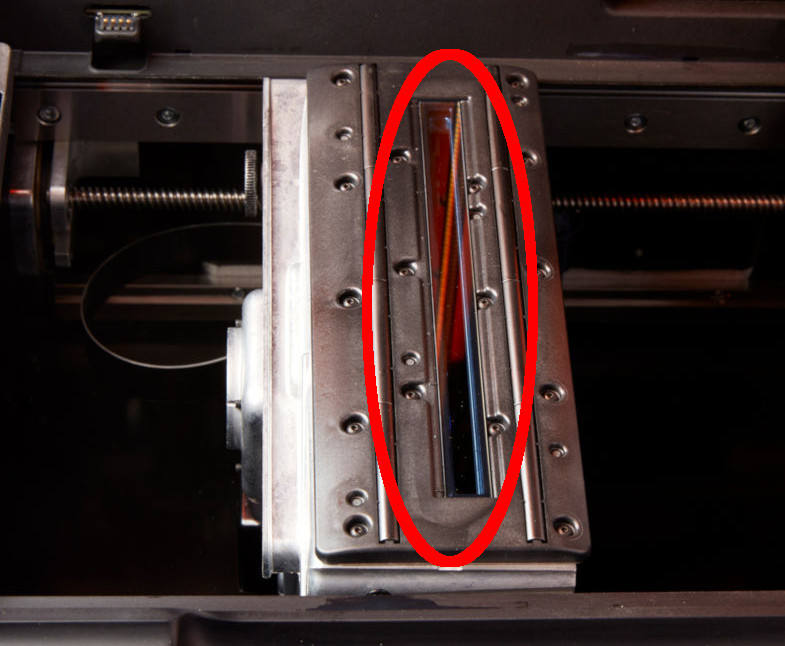 |
| X-axis lead screw | The X-axis lead screw the horizontal motion of the LPU housing. |  |