
Required supplies:
- 1.3 mm hex driver
- 1.5 mm hex driver
- 2.5 mm hex driver
- Tweezers and/or a small flat-blade screwdriver
- Hot rework tweezers or other appropriate SMD soldering equipment
- Nitrile gloves

The Form Wash L has Wi-Fi functionality for receiving firmware updates and uploading log files. Wi-Fi can be turned off via the machine’s touchscreen, but depending on your organization's security requirements, you may need to physically remove the Wi-Fi hardware before using the device. This hardware includes a component on the system on a module (SOM) plugged into the motherboard as well as a Wi-Fi antenna plugged into the SOM.
Use this guide to remove all Wi-Fi hardware from the Form Wash L.
Required supplies:
Estimated time: 45–60 minutes
Preparing the workspace
Overview: Prepare the Form Wash L and a dust-free workspace for removing and modifying the SOM.
Step 1: Prepare the workspace
Clear a workspace around your machine. Ensure that the workspace is well-ventilated and free of dust.
Step 2: Unplug the networking cables and Wi-Fi antenna
Disconnect the Ethernet and USB cables from the unit, if they are connected. Unscrew and remove the Wi-Fi antenna.
Step 3: Unplug the machine
DANGER:
Performing maintenance on the machine while it is plugged in increases the risk of electric shock. Never remove the panels of the machine while it is plugged in. Never reconnect the machine to power while the panels are uninstalled.
Disconnect the power cable from the machine before continuing with maintenance. Do not perform maintenance on the machine while it is connected to power. Wait five minutes after disconnecting the machine from power before proceeding.
Removing the right shell
Overview: Remove the right shell of the machine to access the SOM.
NOTICE:
The Form Wash L contains sensitive electronic components. Ground yourself before touching any electronics in the machine by using a grounding strap or touching a grounded piece of metal.
Step 1: Unscrew the right shell screws
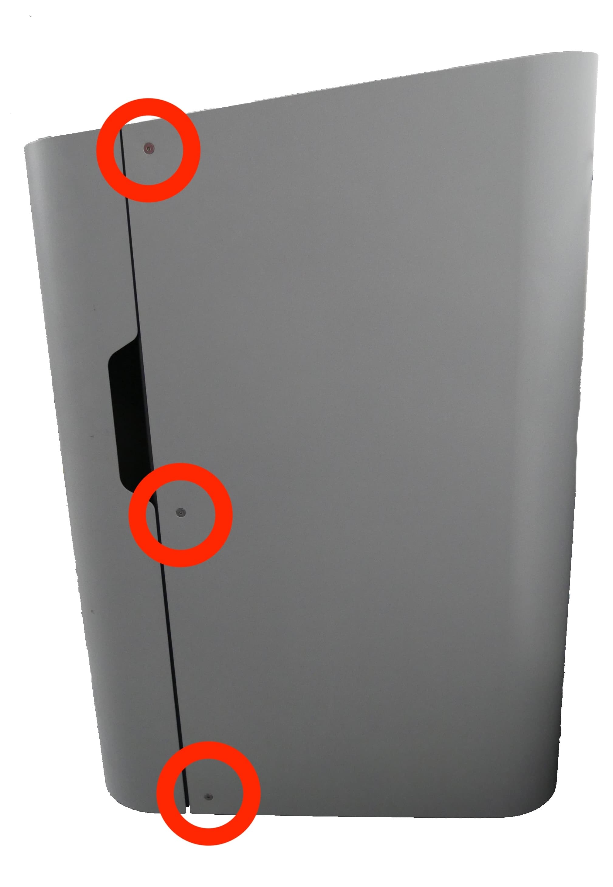
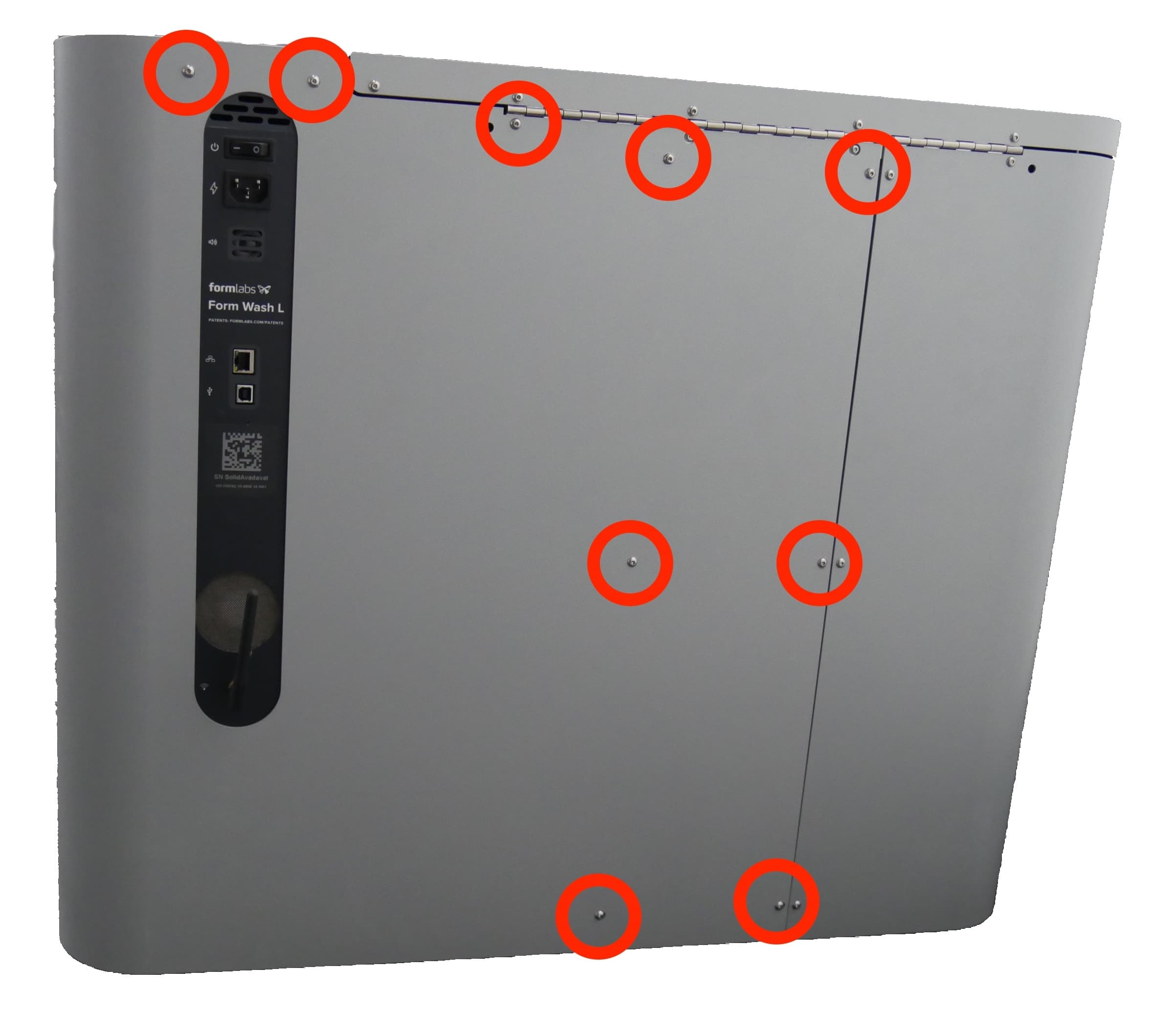
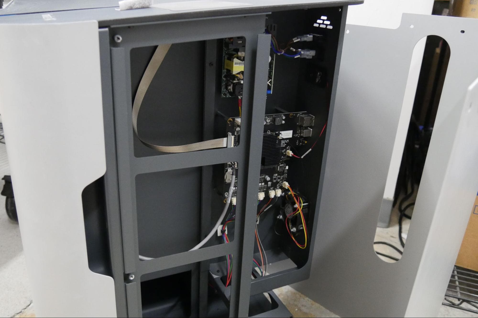
Use the 2.5 mm hex driver to loosen and remove the 12 screws holding the right shell to the frame of the Form Wash L. Three countersunk screws are located on the right side of the machine and nine button head screws are located on the rear. Set the screws aside.
Notice:
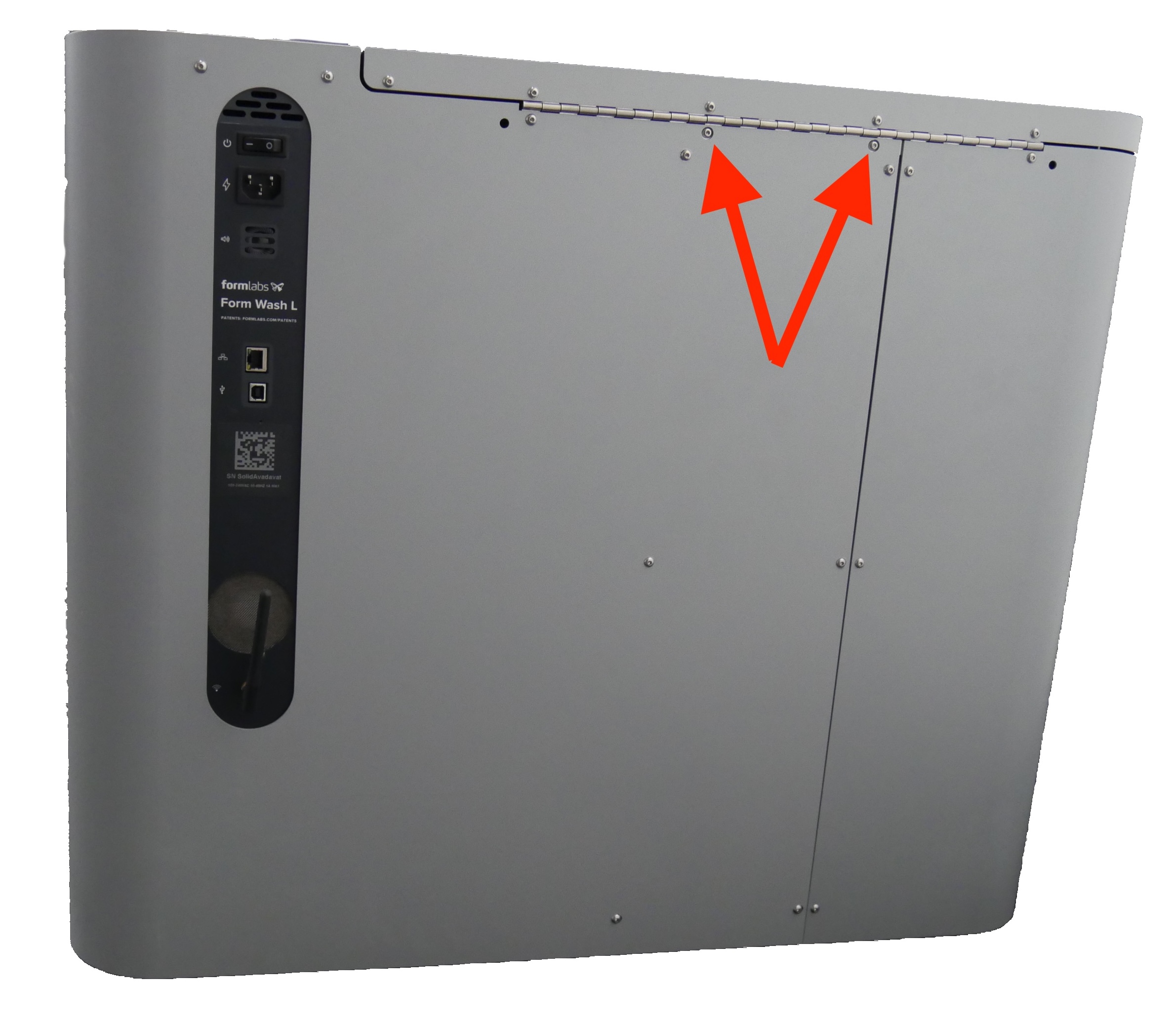
There are two screws, accessible through cutouts in the right shell, that secure the lid to the frame of the machine. Do not remove these screws during this procedure.
Pull the right shell away from the Form Wash L to separate it from the machine’s frame. Set the right shell aside.
Removing the SOM
Overview: Unscrew and uninstall the SOM.
Step 1: Disconnect the Wi-Fi antenna from the SOM
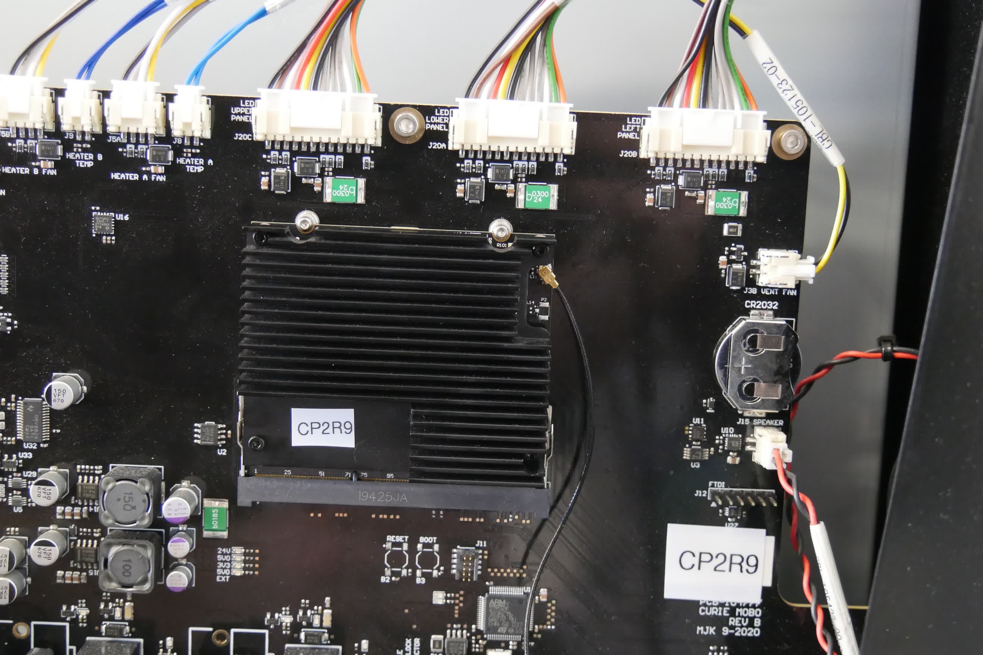
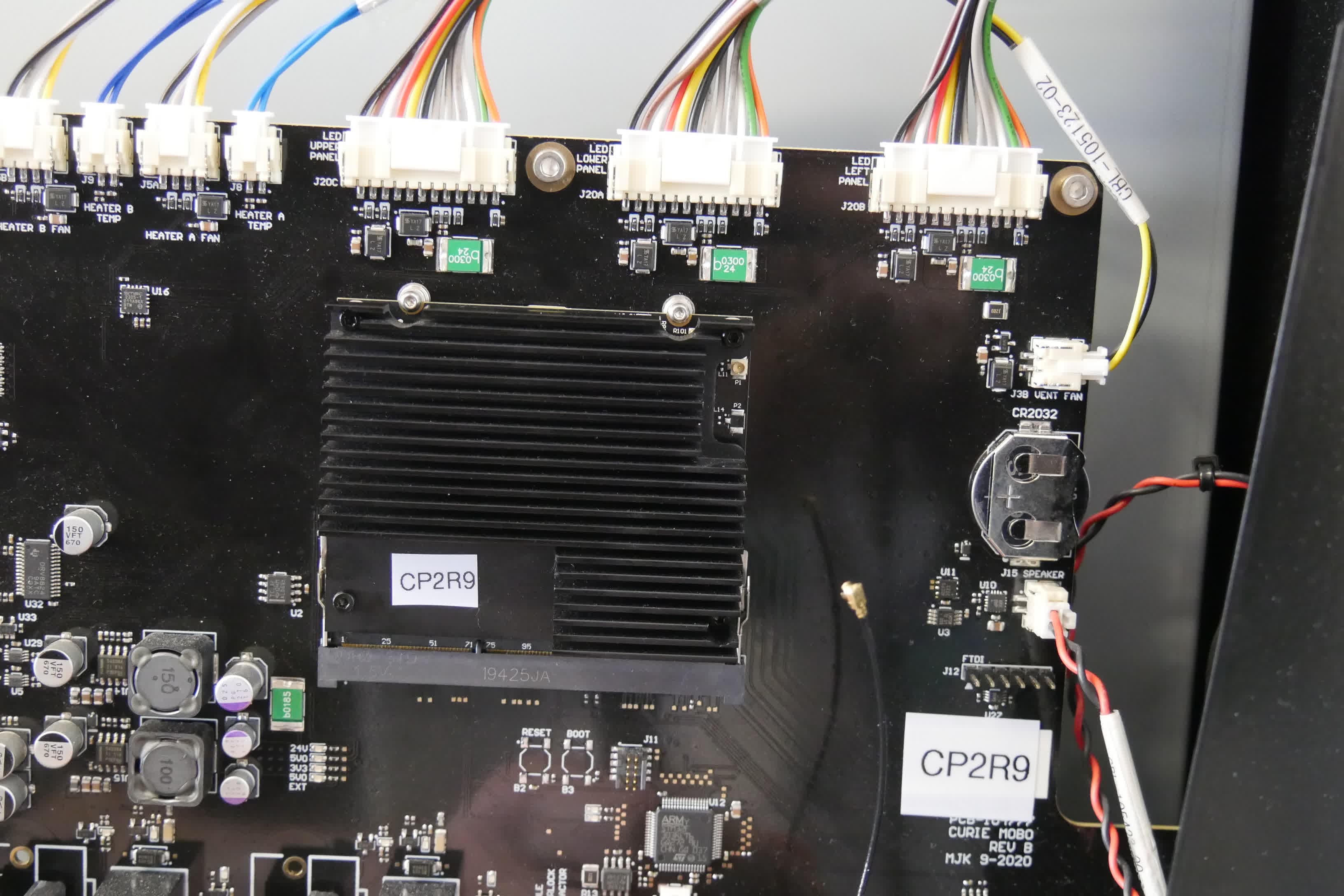
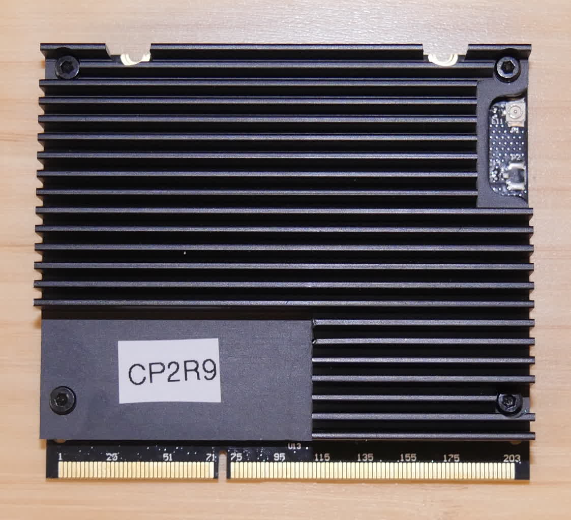
The Wi-Fi antenna is plugged into the SOM at the top-right corner of the board. The connector is accessible through a cutout in the heatsink. Grip the antenna’s connector by its housing and disconnect it from the SOM. Do not pull on the antenna itself.
Step 2: Unscrew the SOM retention screws
The SOM is plugged into the motherboard and secured with two screws on the top side of the module. Using a 1.3 mm hex driver, loosen and remove two SOM retention screws. Set the screws aside.
Step 3: Unlatch the SOM
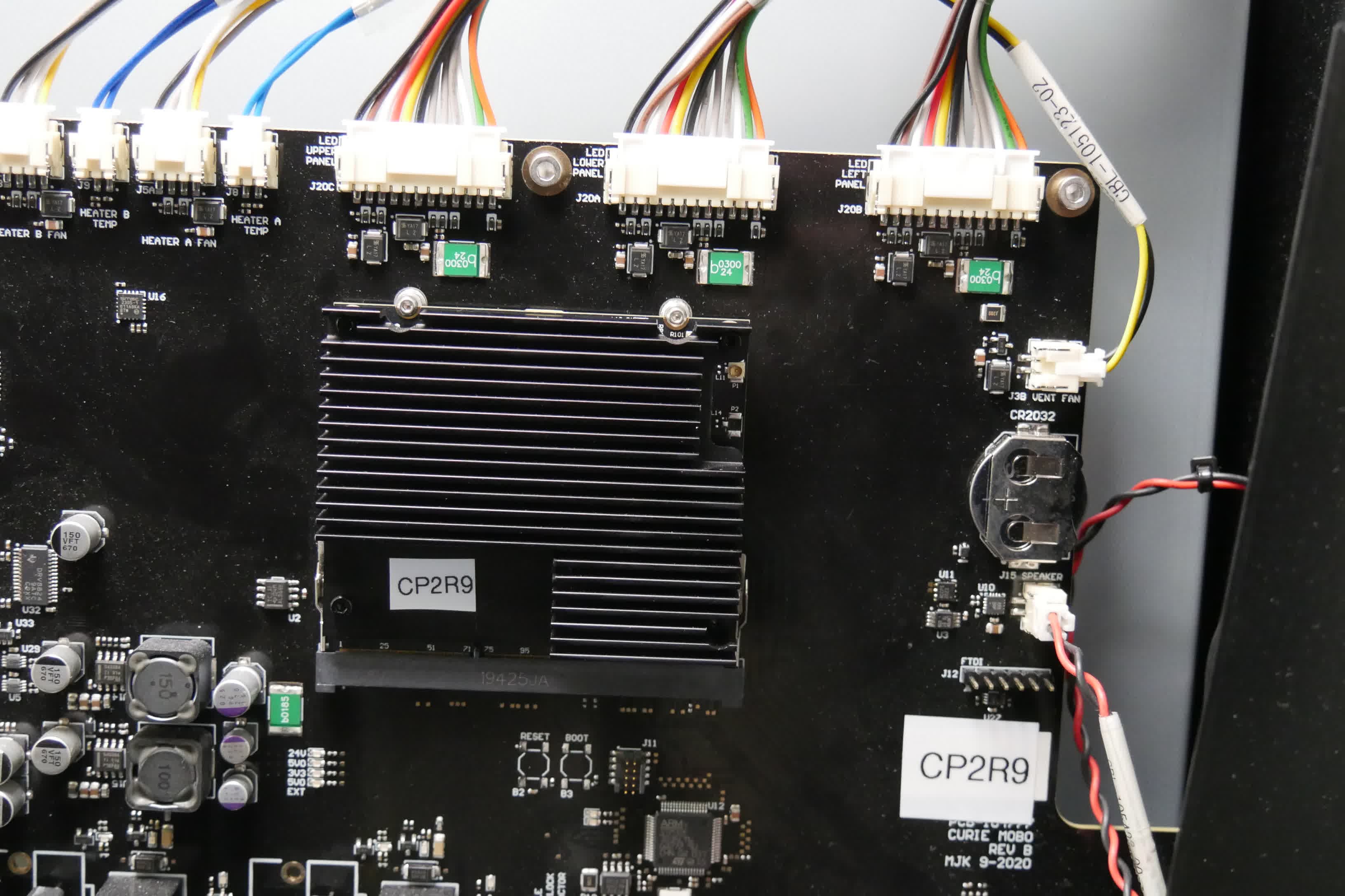
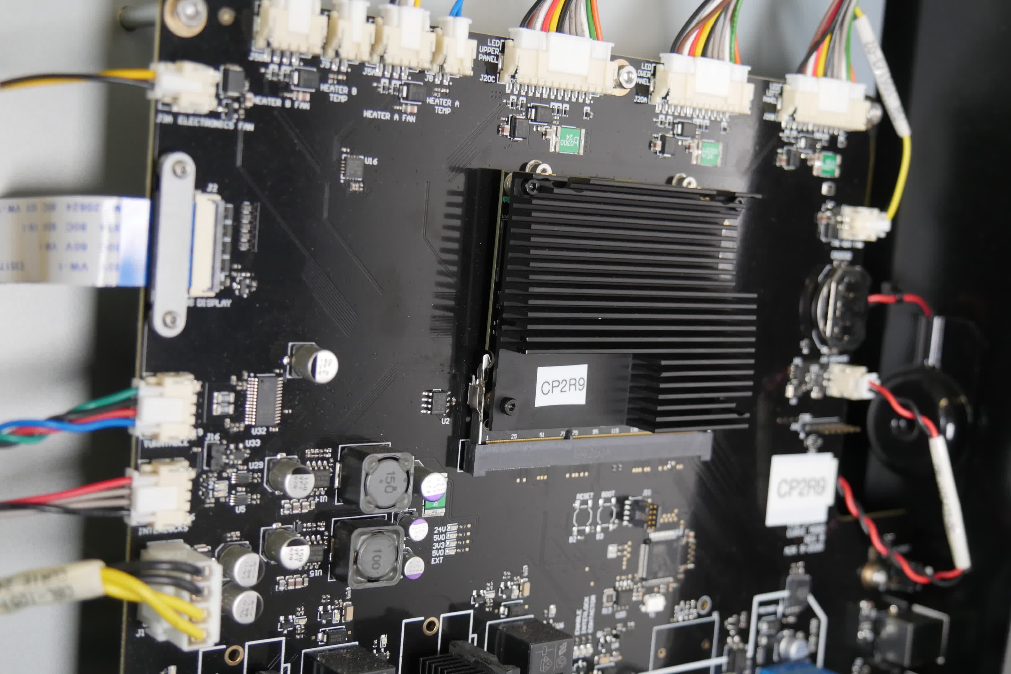
The SOM is additionally secured via two latches: one on the left side of the board and one on the right. Using fingernails or a small flat-blade screwdriver, open the two latches securing the SOM into its socket. The SOM may tilt forward once you have opened both latches.
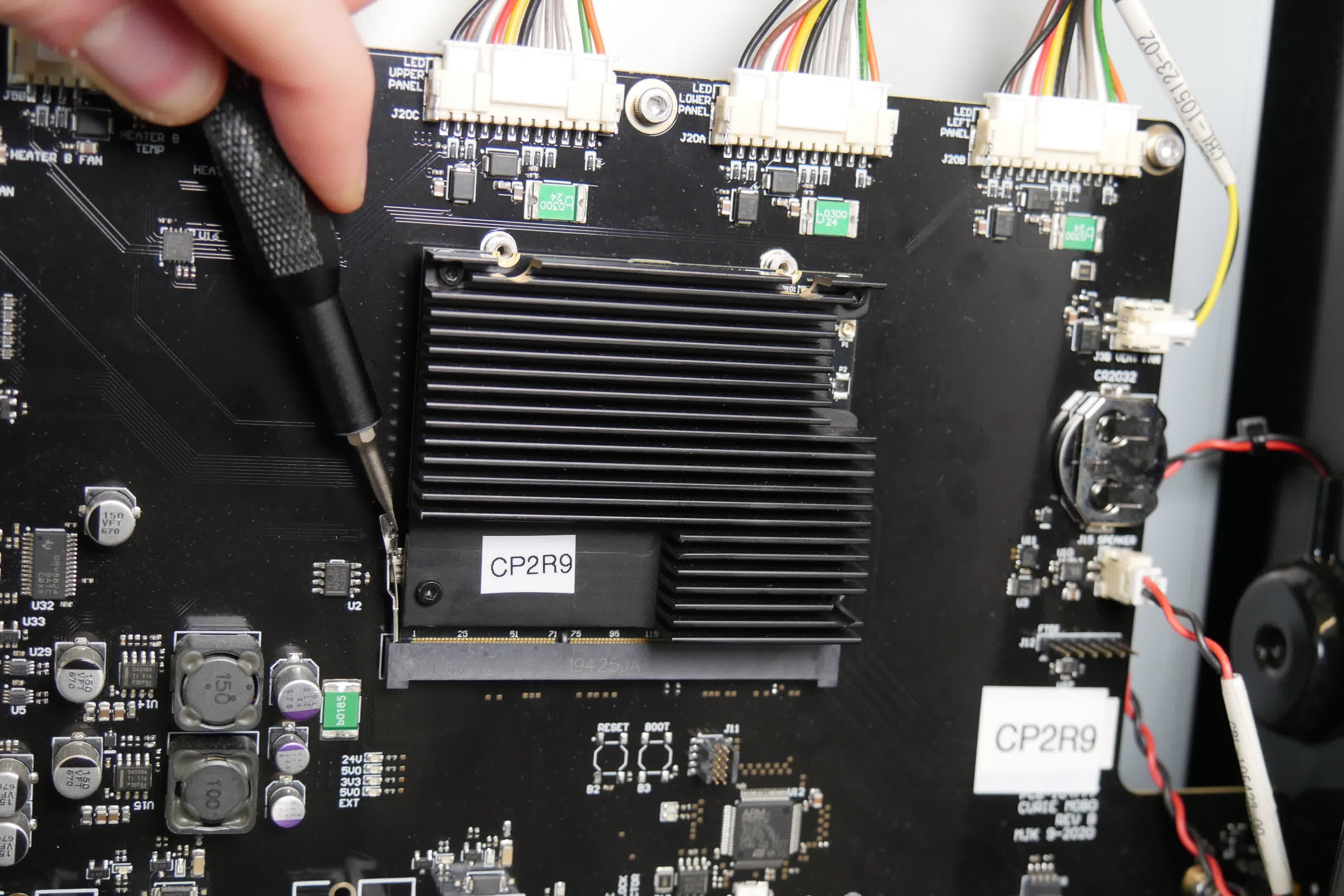
Remove the SOM
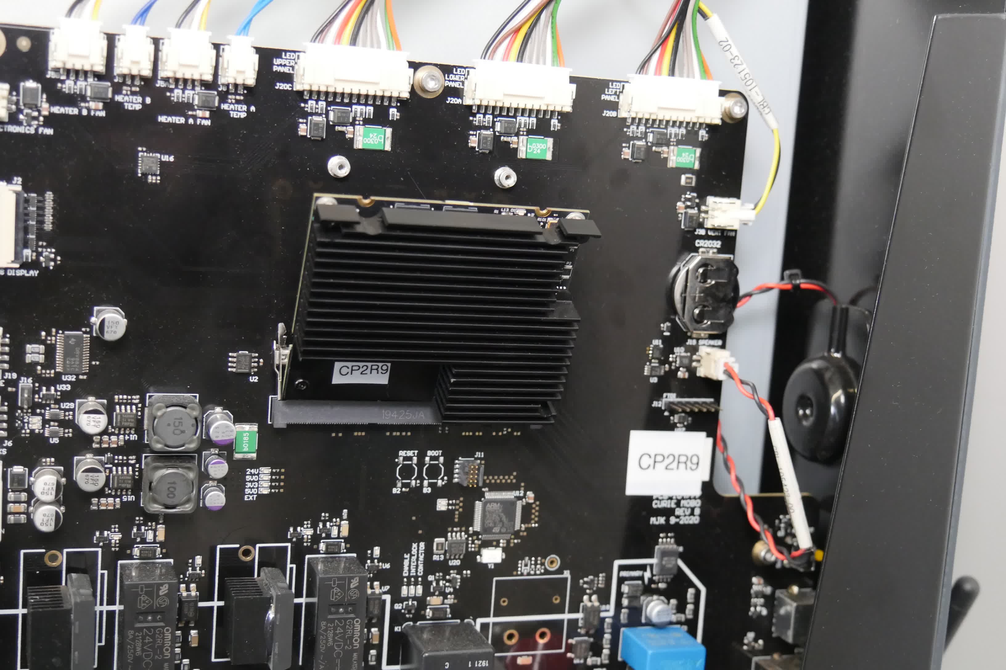
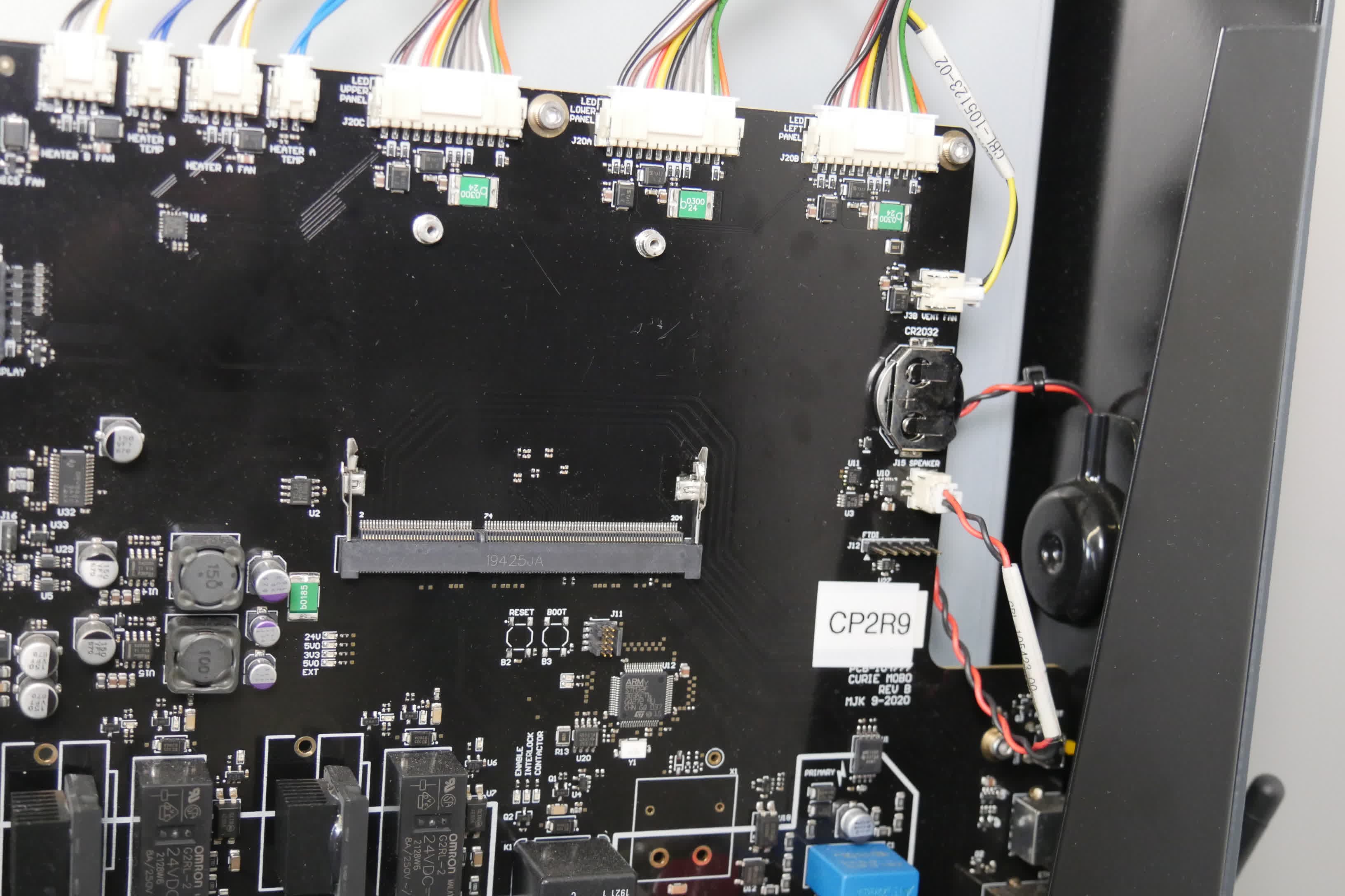
Lift the SOM up from the edge opposite its connector and carefully pull it free from the socket. Place the SOM on a static-free surface.
Modifying the SOM
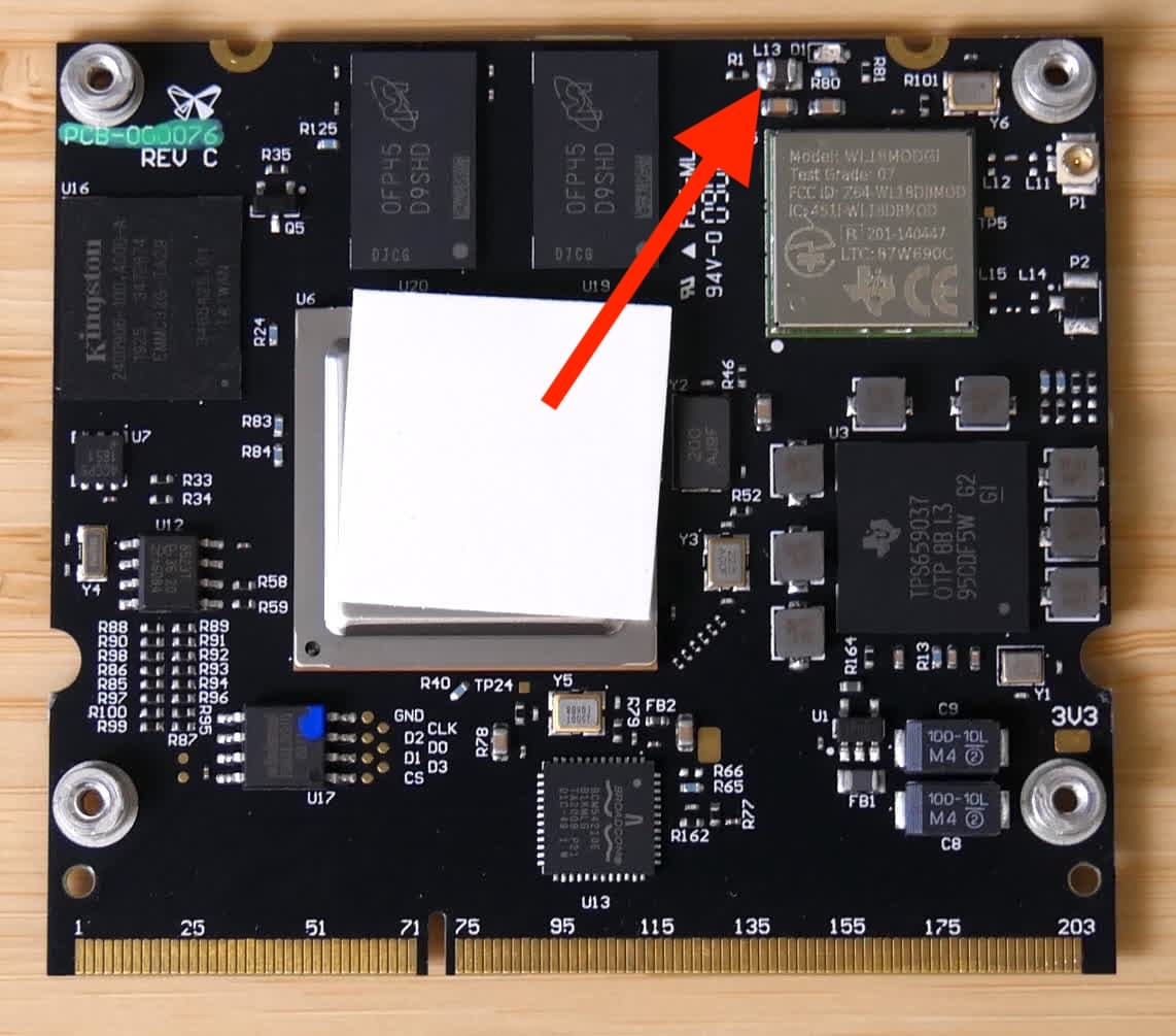
Overview: After removing the SOM from the machine, remove component L13.
Unscrew and remove the heatsink
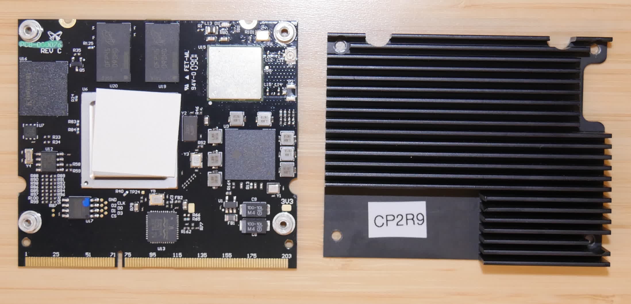
Using a 1.5 mm hex hex driver, unscrew and remove the four screws securing the heatsink to the SOM. Set the screws aside. Remove the heatsink and set it aside.
Using hot tweezers or other appropriate SMD soldering equipment, remove component L13 from the SOM. If you plan to reverse this procedure in the future, save component L13 for later reuse.
Reinstalling the SOM
Overview: After modifying the SOM, reinstall the heatsink and reconnect the SOM to the motherboard.
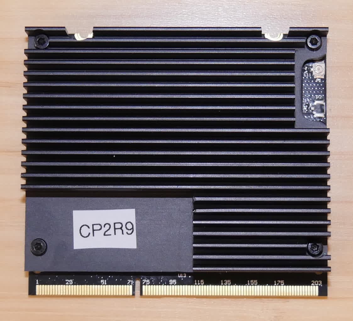
Reinstall the heatsink onto the SOM, making sure the thermal pad on the bottom of the heatsink covers the processor (the largest chip on the board, labeled U6). Ensure that the cutout on the edge of the heatsink allows access to the Wi-Fi antenna port and that the screw holes in the heatsink align with the holes in the SOM.
Insert one heatsink retention screw into each of the four screw holes in the heatsink. Using a 1.5 mm hex driver, tighten the four screws until finger tight. Do not overtighten.
Step 2: Reinstall and secure the SOM
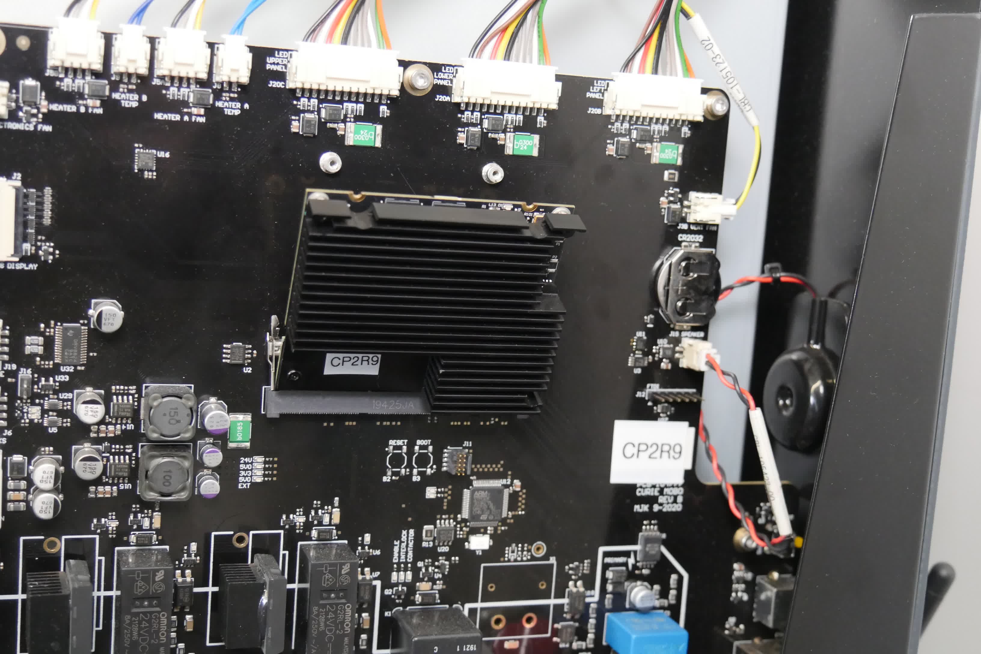
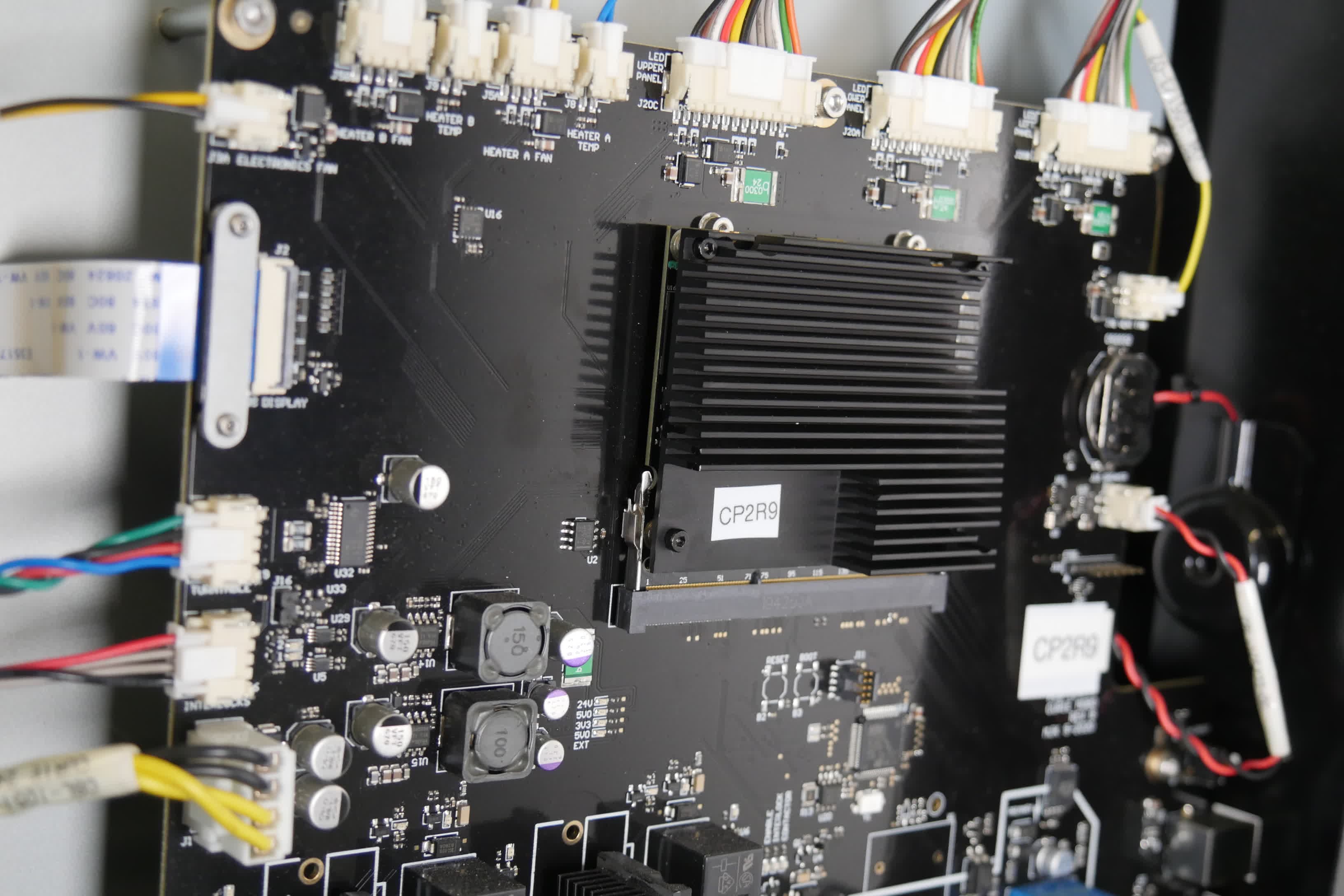
Insert the SOM into its socket on the motherboard at an angle, then tilt it towards the motherboard until the two latches close. Insert one SOM retention screw into both of the screw holes on the top edge of the SOM. Using a 1.3 mm hex driver, tighten the two screws until finger tight. Do not overtighten.
Step 3: Secure the loose Wi-Fi antenna
Bundle up the end of the cable that was previously connected to the SOM. Cover the connector with insulating tape so it cannot short out any parts in the machine. Tuck the bundled end of the cable into the machine such that it will not be damaged when you reinstall the top shell. As an alternative, remove the antenna from the machine completely. If you plan to reverse this procedure in the future, save the antenna for later reuse.
Reinstalling the right shell
Overview: Reinstall and secure the right shell.
Step 1: Reinstall the right shell
Hold the right shell against the Form Wash L. Check that the screw holes in the right shell line up with the corresponding screw holes in the frame of the machine. Loosely thread the three countersunk 2.5 mm hex screws into the screw holes on the right side of the machine and the nine button head screws into the screw holes on the back of the machine.
Step 2: Secure the right shell
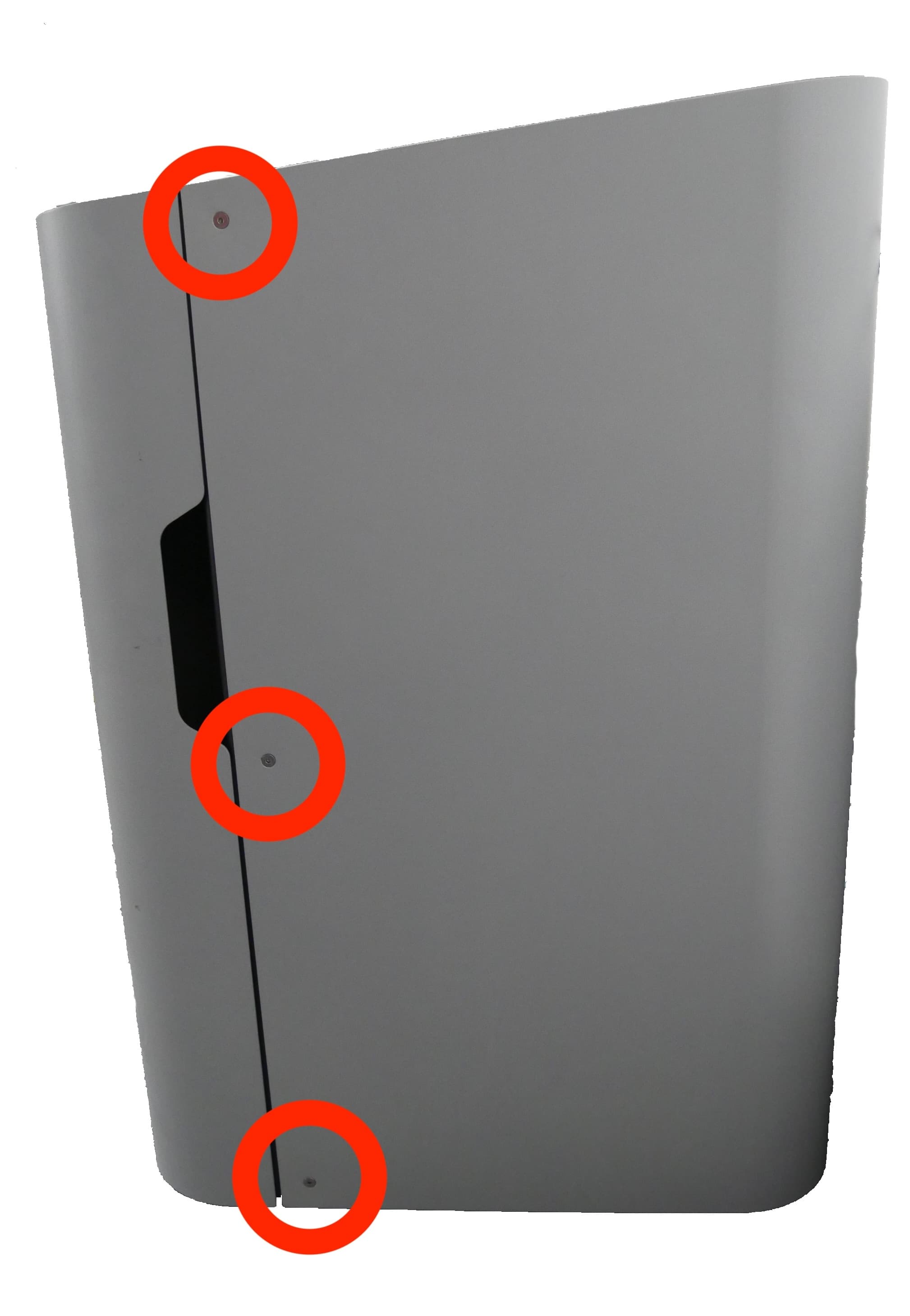
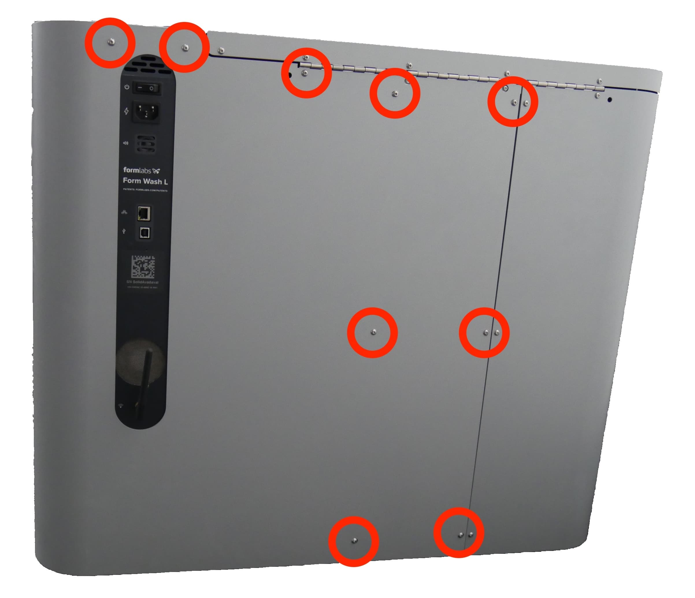
Starting with the screws on the right side of the machine, tighten the screws using a 2.5 mm hex driver until finger tight.
Finalizing the repair
Overview: After reinstalling the right shell, power on the machine and perform final checks.
Step 1: Power on the machine
Reconnect the power cable to the Form Wash L. Flip the breaker switch on the back of the unit to the ON position to turn on the machine.
Step 2: Test the repair
Connect the power cable to the Form Wash L and the power supply. The machine initializes. Test the machine to ensure that it operates normally (with the exception of Wi-Fi connectivity).