
Required supplies:
Formlabs:
- Replacement display assembly
Third-party:
- 2.5 mm hex driver
- T6 Torx driver
- Phillips driver
- Nitrile gloves

The Form 3 has a touchscreen in its front shell. The touchscreen is the primary means of interacting with and controlling the printer, so a broken or malfunctioning touchscreen can prevent the printer from being used normally.
Use this guide to replace the Form 3 display assembly.
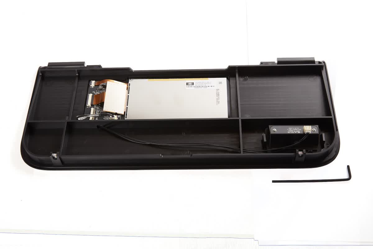
Required supplies:
Formlabs:
Third-party:
Estimated time: 20–30 minutes
DANGER:
Read and follow all safety instructions and warnings in the operator manual. Replacement with incorrect parts can lead to burns, shock, fire, or explosion. Dispose of all parts in accordance with local regulations.
Preparing the workspace
Overview: Prepare the Form 3 and a dust-free workspace for replacing the display assembly.
Step 1: Remove the build platform
Remove the build platform first to avoid dripping resin onto the LPU or into the printer cavity.
Step 2: Remove the resin cartridge
Remove the resin cartridge and close the vent cap to prevent resin from dripping off the bite valve and into the printer.
Step 3: Remove and store the resin tank
Remove the resin tank, place it in the resin tank carrier, and cover it with its lid. Set the carrier and tank aside on a clean, flat surface.
NOTICE:
Wear gloves and hold the resin tank by the tank grips on either side to avoid contamination or damage to the underside of the tank.
Step 4: Prepare the workspace
Clear a workspace around your printer. Ensure that the workspace is well-ventilated and free of dust. Prepare additional space for storing the rear panel of the printer during maintenance.
Step 5: Unplug the printer
Disconnect the power cable before continuing with maintenance. Do not perform maintenance on the printer while it is connected to power. Wait five minutes after disconnecting the printer from power before proceeding.
DANGER:
Performing maintenance on the printer while it is plugged in increases the risk of electric shock. Never remove the back panel of the printer while the printer is plugged in. Never reconnect the printer to power while the back panel is uninstalled.
Step 6: Clean the printer cavity
WARNING:
Resin may cause skin irritation or an allergic skin reaction. Wear gloves when handling liquid resin or resin-coated surfaces. Wash skin with plenty of soap and water.
Open the printer cover. Check inside the printer cavity to ensure that no resin has pooled on the printer floor. Clean any resin inside the printer cavity with paper towels. Dampen the paper towels with isopropyl alcohol if necessary to fully remove the resin.
DANGER:
IPA is flammable and presents a fire hazard. Keep containers closed, and keep out of the reach of children.
Removing the display assembly
Overview: Unscrew and uninstall the display assembly.
NOTICE:
The Form 3 contains sensitive electronic components. Ground yourself before touching any electronics in the printer by using a grounding strap or touching a grounded piece of metal.
Step 1: Remove the display screws
Place the printer at the front of your work surface so that the front edge of the printer overhangs the front edge of the work surface. Locate the two 2.5 mm hex screws at the front of the bottom shell. These screws secure the display to the printer frame. Use the 2.5 mm hex driver to loosen the two screws. Remove the screws and set them aside.
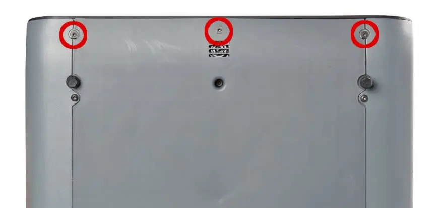
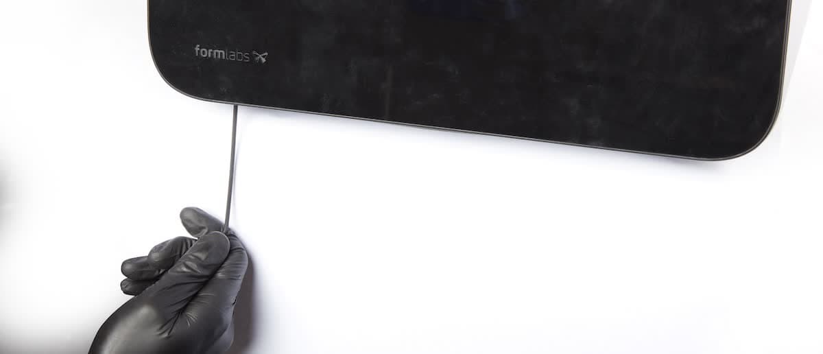
Depending on the date of manufacture, your printer may have a third screw located between the two 2.5 mm hex screws. The third screw is either a T6 Torx screw or a Phillips screw. If this third screw is present, remove it and set it aside.
NOTICE:
Once the display screws are removed, the display assembly is no longer secured to the printer frame. To prevent damage to the display ribbon cable, read the remaining steps in this guide before continuing.
Step 2: Separate the display assembly from the printer frame
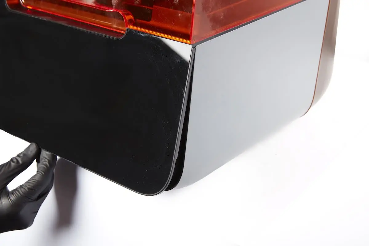
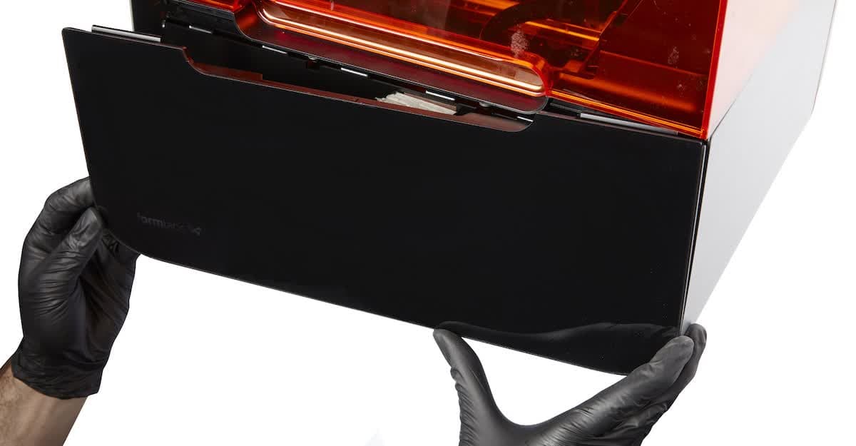
The top of the display assembly is held to the printer frame via a set of plastic tabs. Tilt the bottom of the display assembly slightly away from the printer, then lower the display assembly to separate it from the printer frame.
Step 3: Rotate the display assembly
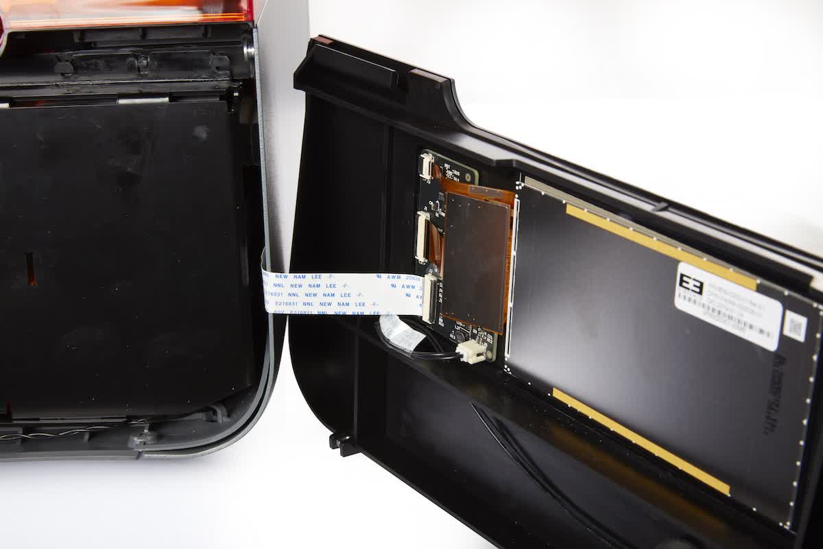
The display ribbon cable connects the display assembly to the printer motherboard. Rotate the display assembly to the right to access the display ribbon cable connector.
NOTICE:
Do not pull on the ribbon cable or pull the display assembly away from the printer. Doing so may damage the display ribbon cable.
The display ribbon cable is secured in the connector with a latch. Lift the latch away from the display assembly to free the display ribbon cable.
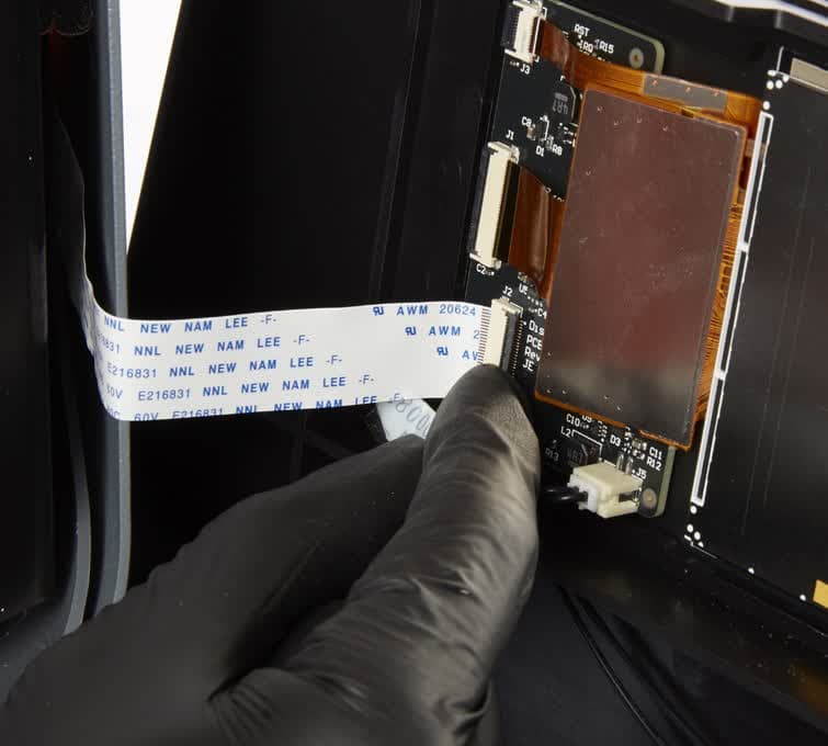
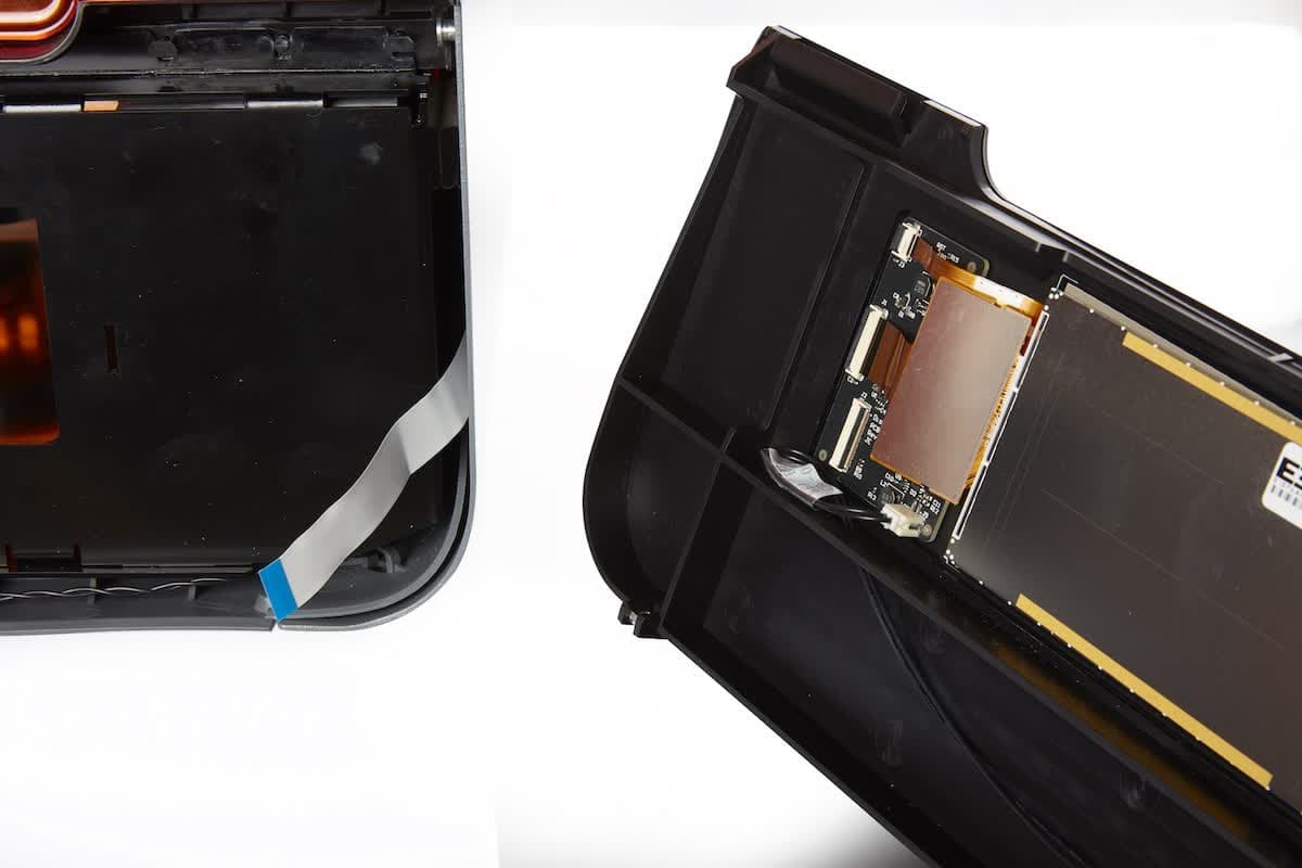
Remove the display ribbon cable from the connector and set the display assembly aside.
Installing the new display assembly
Overview: Mount and secure the new display assembly.
Step 1: Reconnect the display ribbon cable
Insert the display ribbon cable into the connector on the new display assembly, ensuring that the ribbon cable is not twisted or folded.
Step 2: Secure the latch
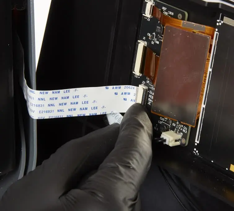
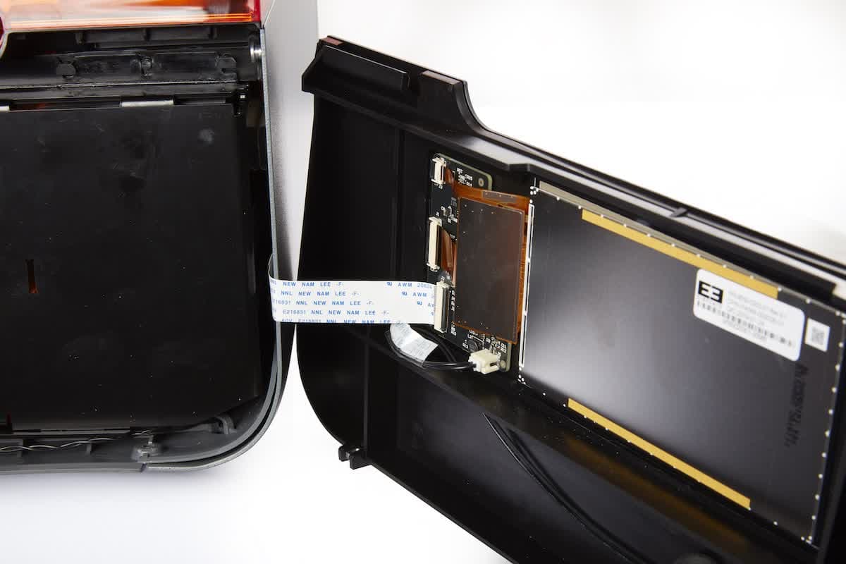
Rotate the latch towards the display assembly to lock the display ribbon cable in place.
Step 3: Install the display assembly
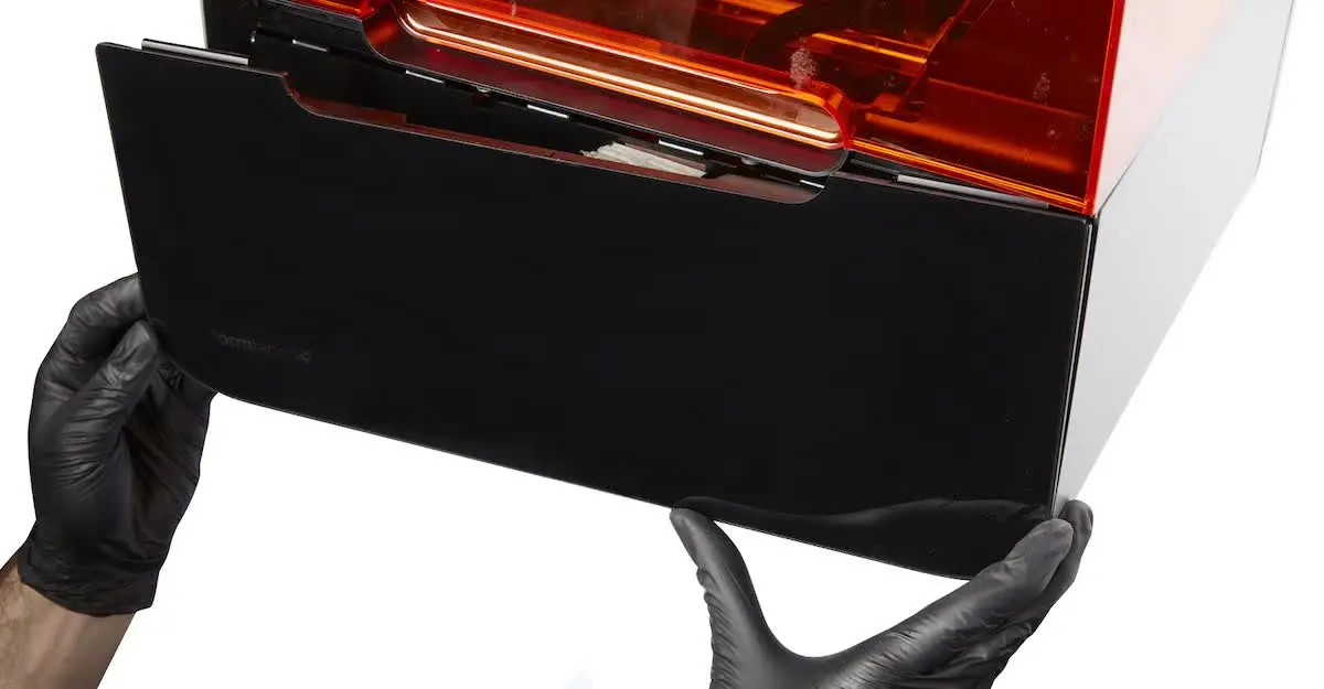
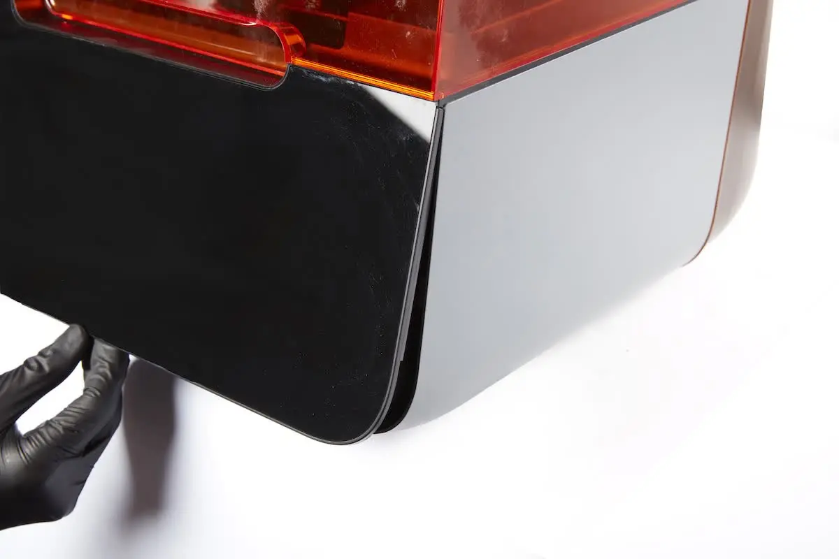
Insert the tabs on the top edge of the display assembly underneath the top shell of the printer. Tilt the bottom edge of the display assembly towards the printer until it lies flush with the bottom shell and side shells. Ensure that the display ribbon cable is not caught between the display assembly and the printer frame.
Step 4: Secure the display assembly
Thread the two 2.5 mm hex screws into the holes at the front of the bottom shell. Use the 2.5 mm hex driver to tighten the screws until snug.
Finalizing the repair
Overview: After installing the new display assembly, power on the printer and perform final checks.
Step 1: Power on the printer
Connect the power cable to the printer and the power supply. The printer will initialize, and the touchscreen will turn on.
Step 2: Test the touchscreen
The touchscreen should respond to touch inputs if the repair was successful. Test a variety of inputs, such as viewing the printer’s settings or exploring past prints via the print queue. Contact Formlabs Support or your authorized reseller to share the results of the procedure.