
Required supplies:
Formlabs:
- Fuse 1 generation IR sensor kit (RP-FS1-IRK-02)
Third-party:
- 2.5 mm hex driver (flat-end)
- 3 mm hex driver (flat-end)
- 6.5 mm slotted screwdriver
- Telescoping mirror
- Non-reactive nitrile gloves

On Fuse 1 generation printers, the infrared (IR) sensor sits on the IR sensor flow body, pointed down at the print bed. If the IR sensor flow body or its seals are damaged, the IR sensor may not be able to measure the temperature of your print or the printer may encounter other errors.
Use this guide to replace the IR sensor flow body on a Fuse 1 printer. To replace this component on a Fuse 1+ 30W printer, see Replacing the Fuse 1+ 30W IR sensor flow body.
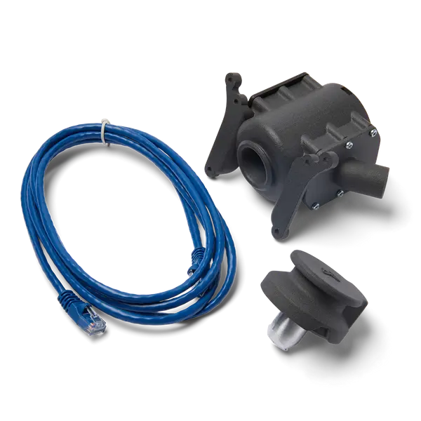
Required supplies:
Formlabs:
Third-party:
Estimated time: 45–60 minutes
Danger:
Read and follow all safety instructions and warnings in the operator manual. Replacement with incorrect parts can lead to burns, shock, fire, or explosion. Dispose of all parts in accordance with local regulations.
Warning:
Do not perform this procedure if the printer was printing less than six hours prior. Failure to do so may result in serious burns. Allow the print enclosure to cool to room temperature before touching or inspecting any Fuse 1 components.
Preparing the workspace
Overview: Prepare the printer and a dust-free workspace for replacing the IR sensor flow body.
Notice:
Fuse 1 generation printers contain sensitive electronic components. Ground yourself before touching any electronics in the printer by using a grounding strap or touching a grounded piece of metal.
Step 1: Prepare the workspace
Clear a workspace around your printer. Ensure that the workspace is well-ventilated and free of dust.
Step 2: Unplug the printer
Disconnect the power cable before continuing with maintenance. Do not perform maintenance on the printer while it is connected to power. Wait five minutes after disconnecting the printer from power before proceeding.
Danger:
Performing maintenance on the printer while it is plugged in increases the risk of electric shock. Never remove the back panel of the printer while the printer is plugged in. Never reconnect the printer to power while the back panel is uninstalled.
Removing the top panel
Overview: Remove the top panel to access the interior of the printer.
Step 1: Remove the top panel screws
Using a 2.5 mm hex driver, remove the 26 6 mm M4 countersunk screws securing the top panel to the printer:
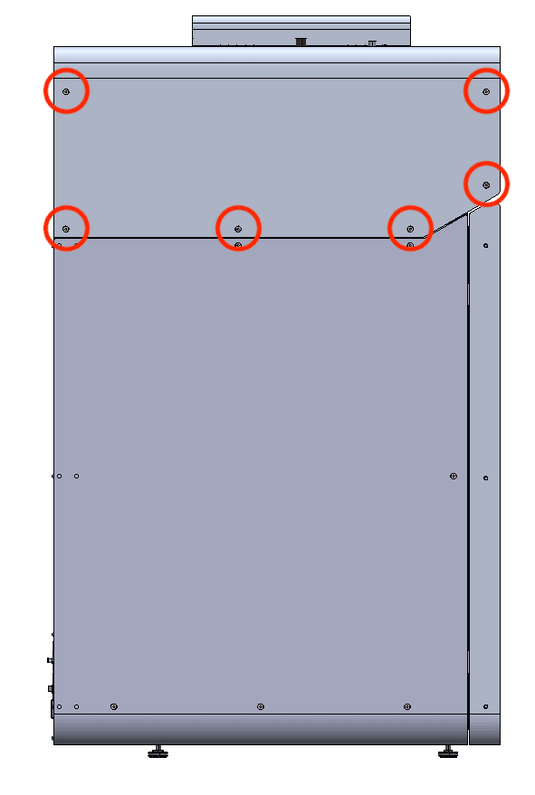
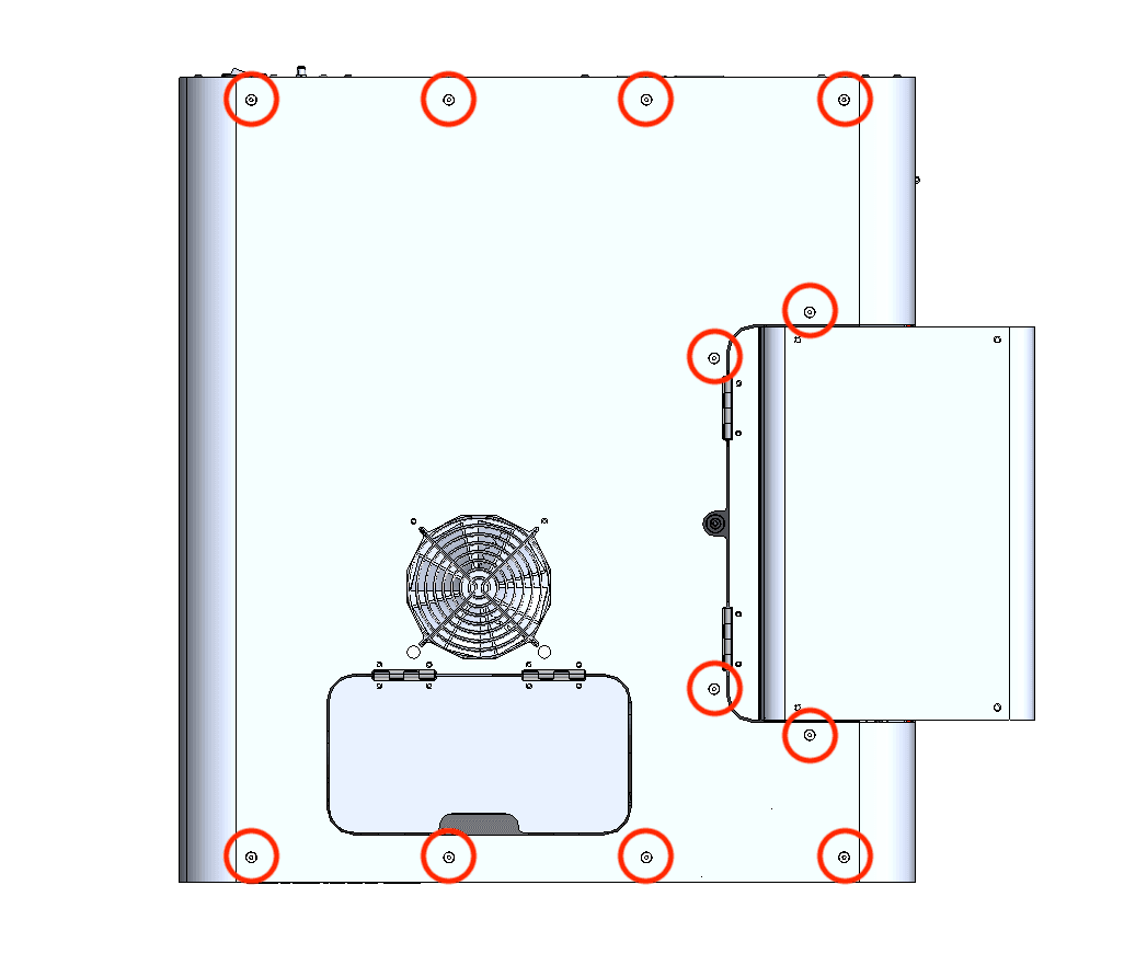
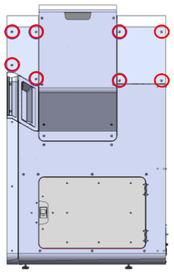
Set the screws aside.
Step 2: Remove the top panel
Lift the top panel off of the printer by grabbing the IR sensor door and the rear-most edge. Set the top panel aside.
Removing the upper cooling shroud
Overview: Remove the upper cooling shroud to access the IR sensor flow body.
Step 1: Remove the IR sensor

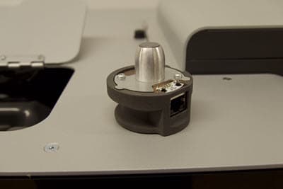
Open the access door to the IR sensor panel, located on top of the printer next to the hopper. Lift the IR sensor and disconnect the cable from it. Set the IR sensor aside on a flat surface with the sensor window facing up. Feed the IR sensor’s cable down through the plastic shroud.
Step 2: Remove the upper cooling shroud screws
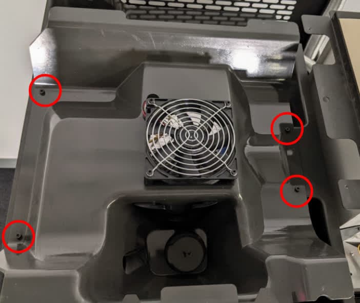
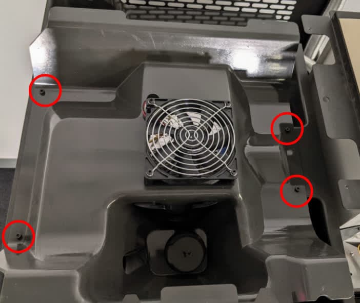
Using a 3 mm hex driver, loosen and remove the four 8 mm M4 socket head screws securing the upper cooling shroud to the printer. Do not yet separate the upper cooling shroud from the printer.
Step 3: Lift the upper cooling shroud
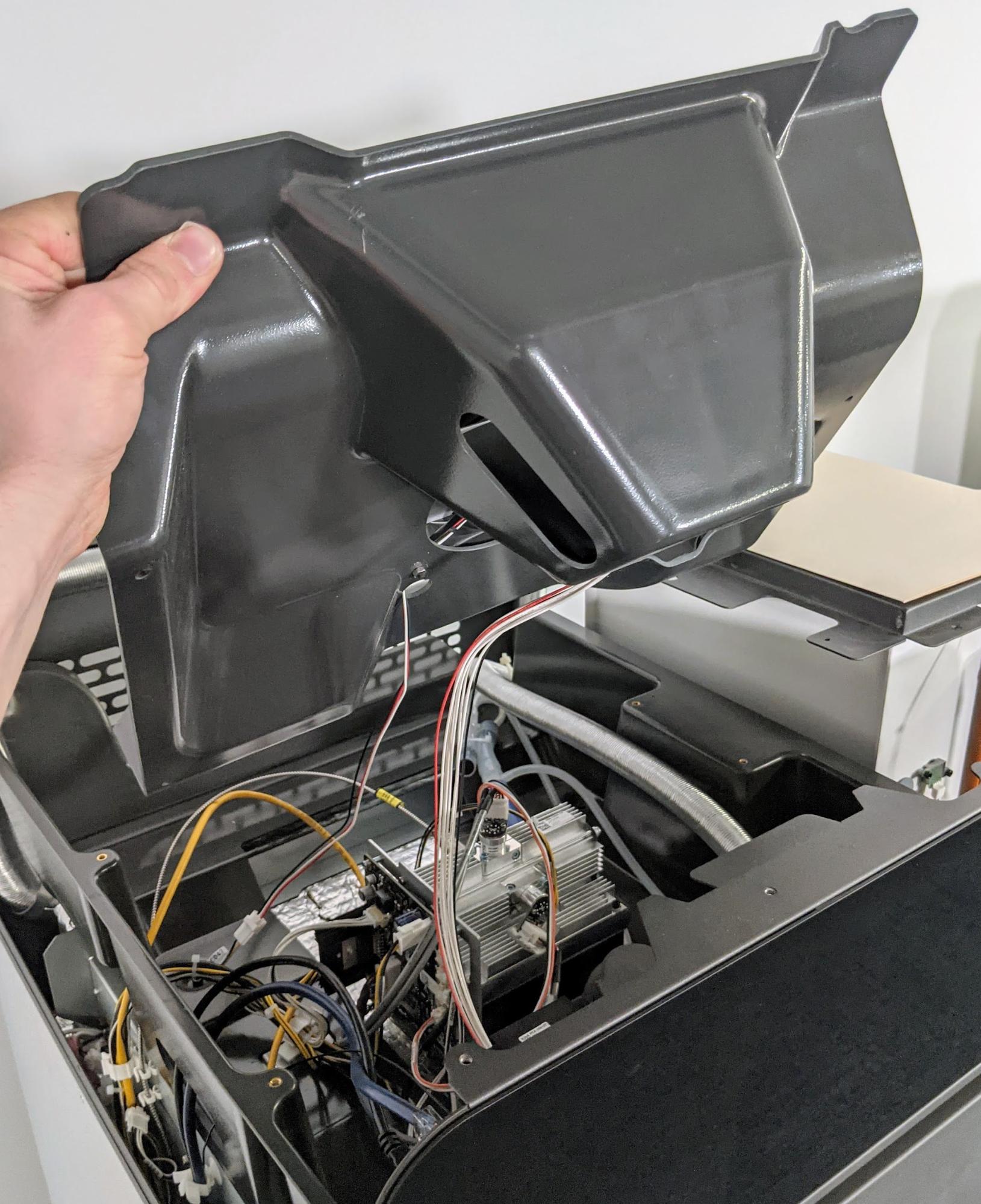
Gently lift up but do not separate the front edge of the plastic shroud from the top of the printer so that the cables attached to the shroud can be accessed.
Notice:
Take care when lifting the plastic shroud so as to not strain the cables attached to it.
Step 4: Unplug the fan cable
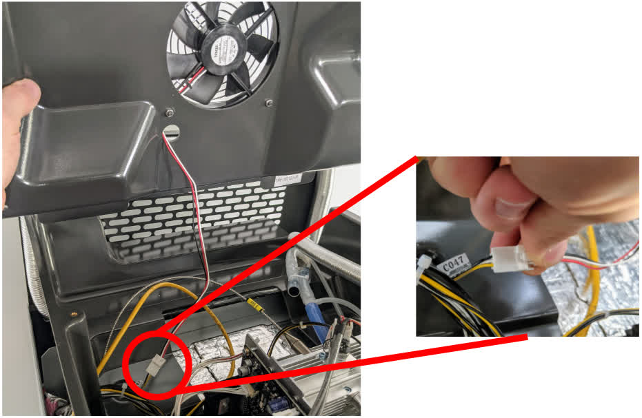
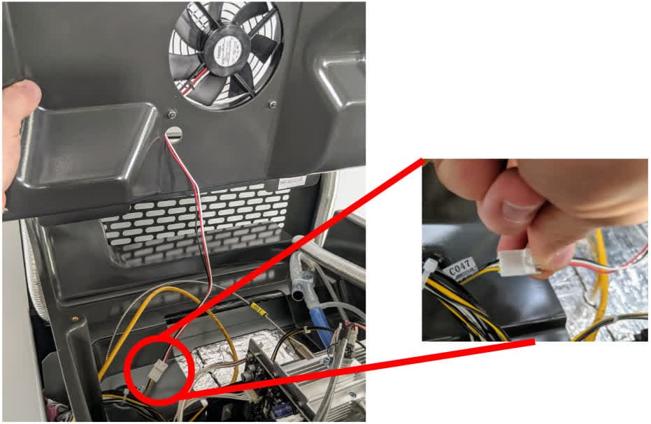
Disconnect the fan cable from the connector labeled C047 by squeezing on the plastic latch. Do not pull on the individual wires; only pull on the plastic connector.
Tip:
It may be helpful to have one person hold the plastic shroud while another person unplugs the cables.
Unplug the RFID reader board cable from the circuit board by gently pulling on the white connector.
Separate the upper cooling shroud from the printer and set it aside.
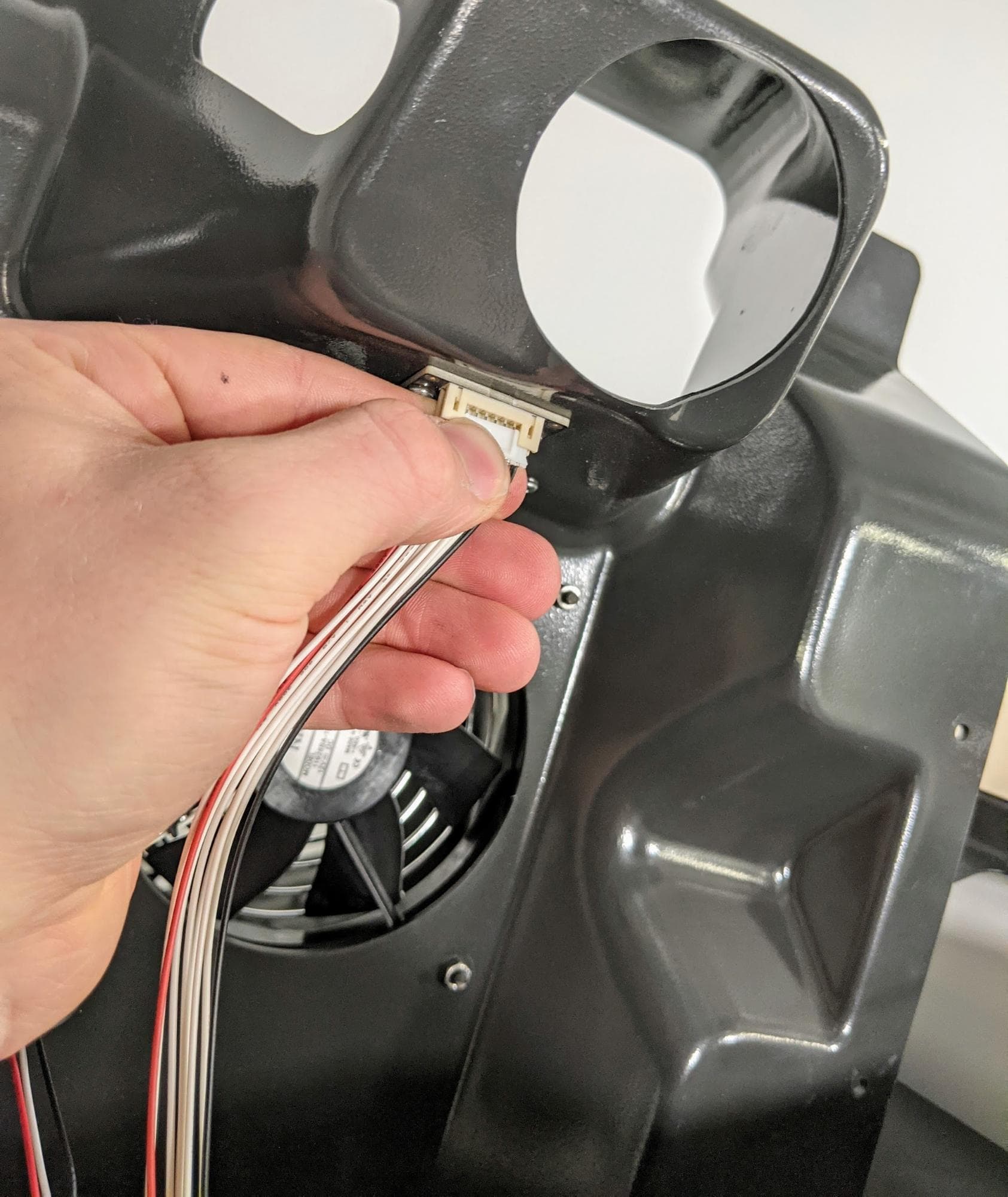
Removing the original IR sensor flow body
Overview: Disconnect and remove the original IR sensor flow body.
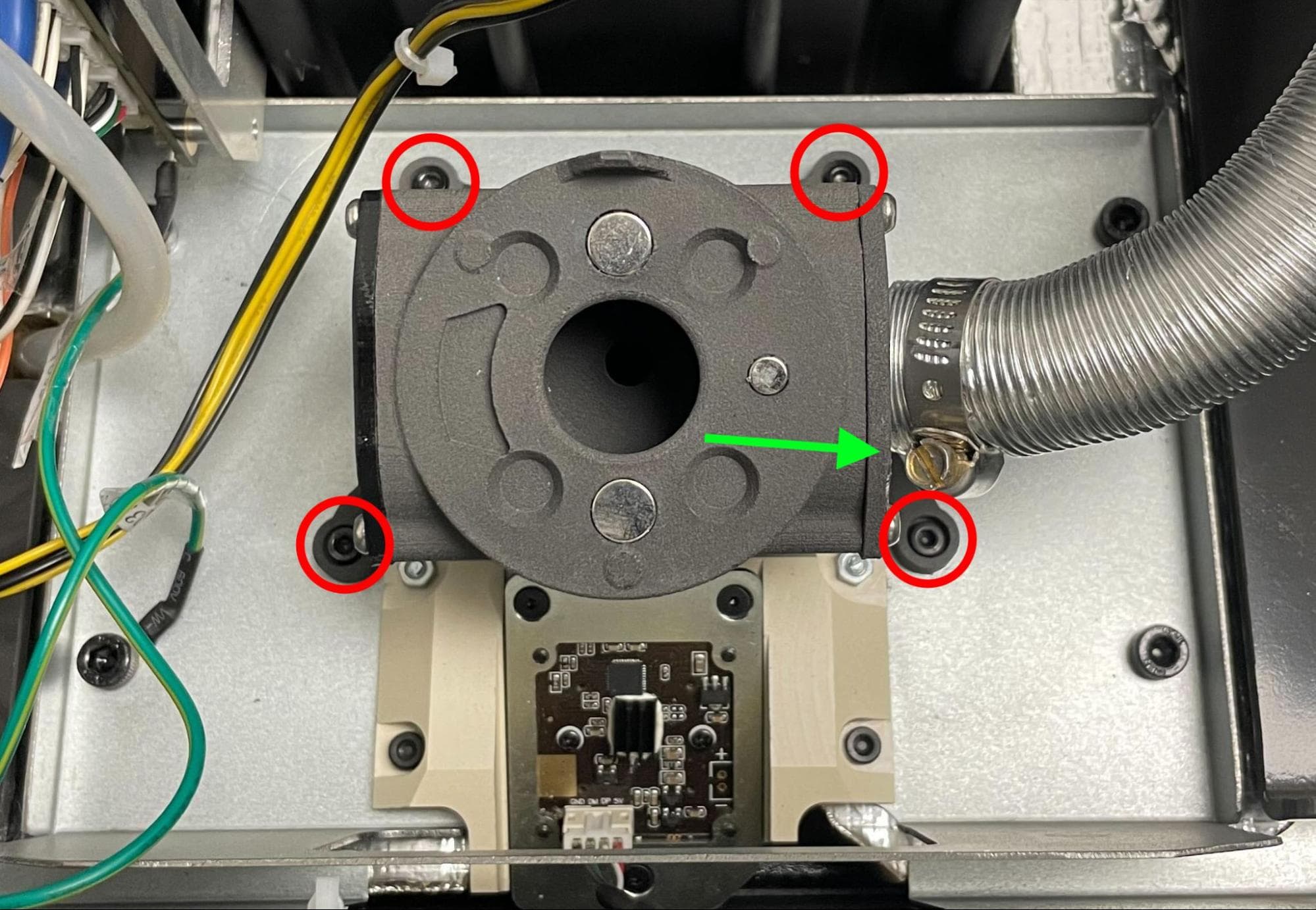
Using a 6.5 mm slotted screwdriver, loosen but do not remove the ring clamp screw on the side of the flow body. Pull the aluminum duct away from the IR sensor flow body.
Using a 2.5 mm hex driver, loosen and remove the four 5 mm M3 socket head screws securing the IR sensor flow body to the printer.
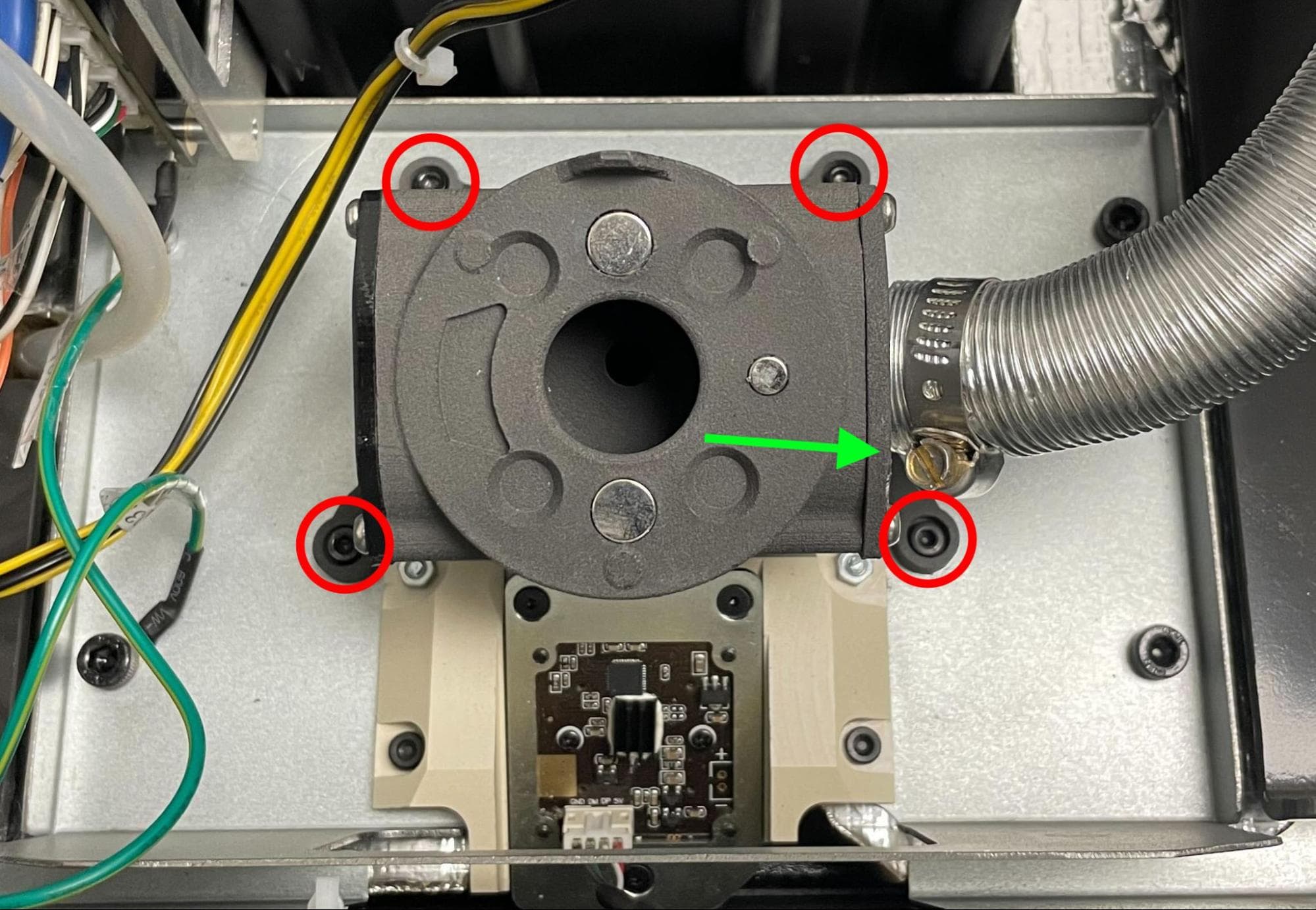
Step 3: Open the print enclosure door
Open the filter cabinet door, then manually open the print enclosure door by pulling the blue release handle. This creates enough space to remove the display assembly.
Look up at the ceiling of the print enclosure. Locate the rubber gasket extending down from the IR sensor flow body. Reach inside the print enclosure with one hand and hold the gasket in place. With your other hand, lift the IR sensor flow body off of the printer. Do not remove the rubber gasket. If it comes loose, reposition it as shown here.
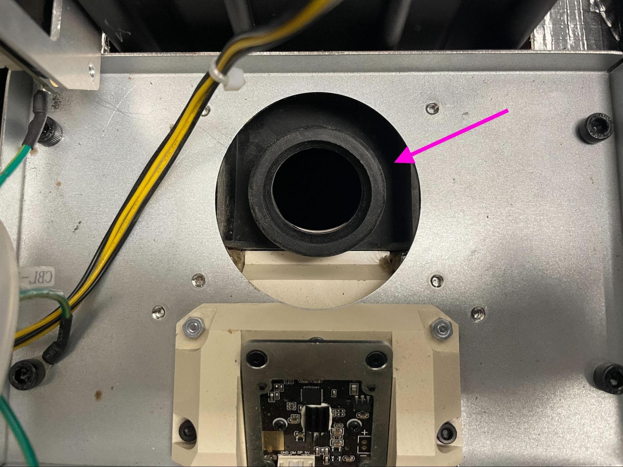
Installing the replacement IR sensor flow body
Overview: Mount, secure, and connect the replacement IR sensor flow body.
Step 1: Mount the IR sensor flow body
Orient the new IR sensor flow body with the IR sensor mount facing up and the hole for the aluminum duct facing right. Position the replacement IR sensor flow body onto the printer but do not secure it.
Step 2: Inspect the IR sensor flow body positioning
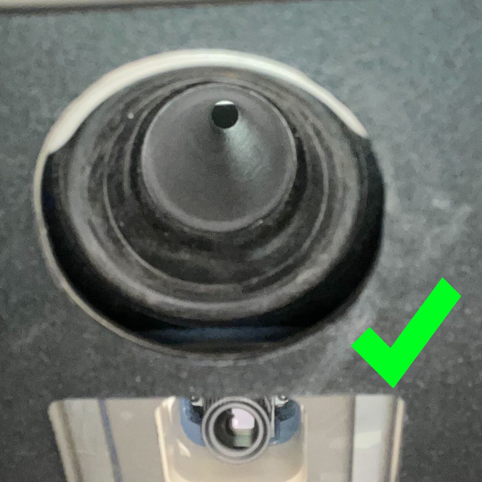


Use a telescoping mirror to inspect the aforementioned rubber gasket from inside the print enclosure. Confirm that the edge of the gasket is even and flush against the printer ceiling, as shown.
Tip:
If the gasket flange is not seated properly, use a gloved finger to guide it into place from inside the print enclosure. If it is difficult to reseat, remove the IR sensor flow body, readjust, and try again.
Once the rubber gasket is properly seated, thread one 5 mm M3 socket head screw into each of the four screw holes in the base of the IR sensor flow body. Using a 2.5 mm hex driver, tighten until snug.
Use a telescoping mirror to check that the rubber gasket did not shift after securing the replacement IR sensor flow body. If it did, readjust its position.
Attach the aluminum duct to the replacement IR sensor flow body, then use a 6.5 mm slotted screwdriver to tighten the ring clamp screw.
Reinstalling the upper cooling shroud
Overview: After replacing the IR sensor flow body, reinstall the upper cooling shroud.
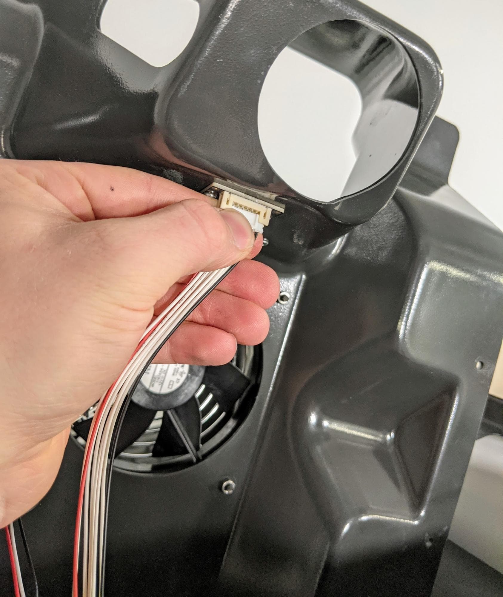
Hold the upper cooling shroud above the printer and plug the RFID reader cable connector into the RFID board by gently pushing it into the receptacle. The connector will only fit in one orientation.
Reconnect the cooling fan connector to the socket labeled C047.
Position the top cooling shroud by holding it from the front edge so that the cables covered by the shroud can still be accessed. Feed the IR sensor’s Ethernet cable back through the cutout in the top shroud.
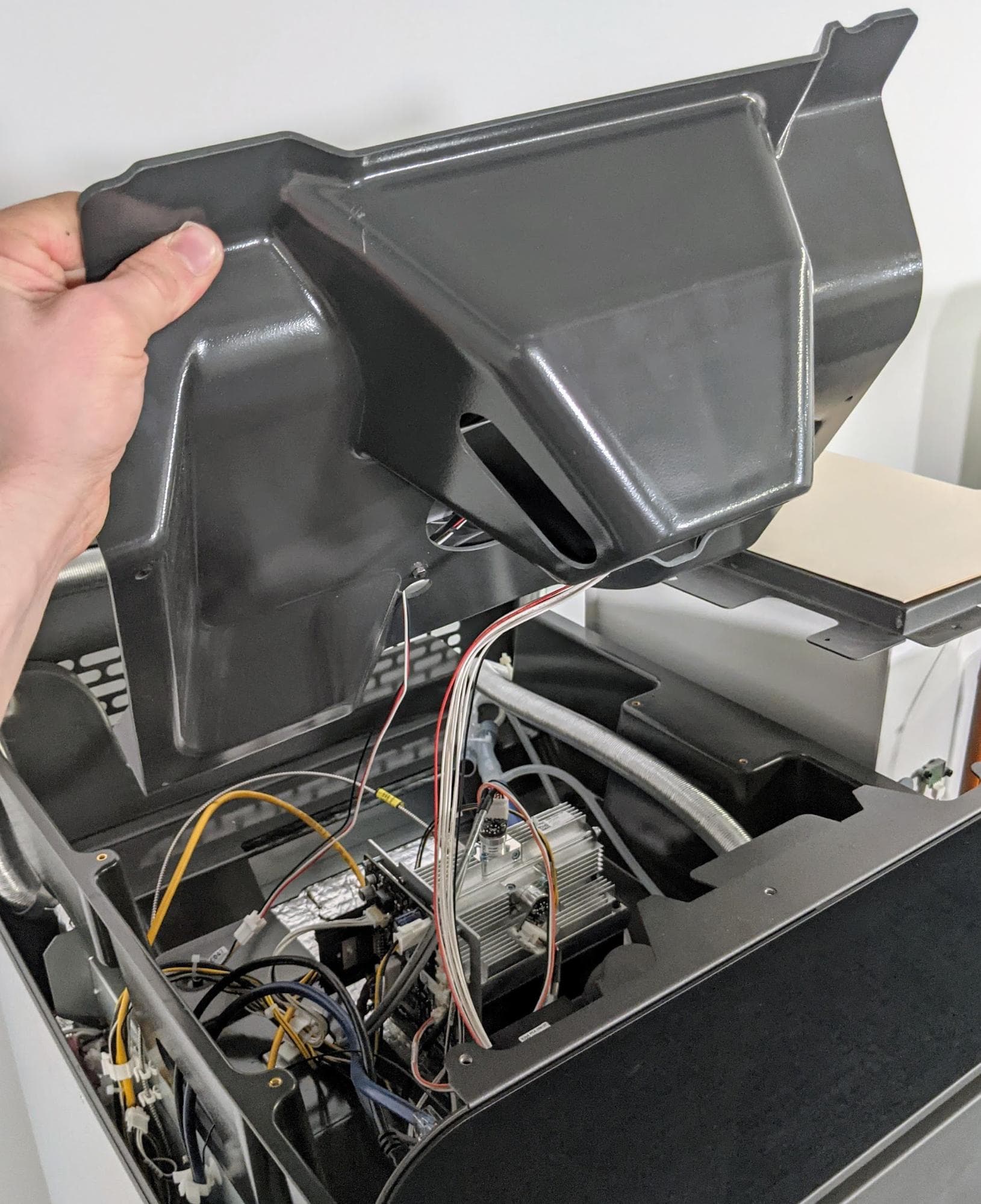
Lower the upper cooling shroud on the printer, aligning the four screw holes in the shroud with the corresponding screw holes in the printer frame. Thread one 8 mm M4 socket head screw into each of the screw holes. Using a 3 mm hex driver, tighten until snug.
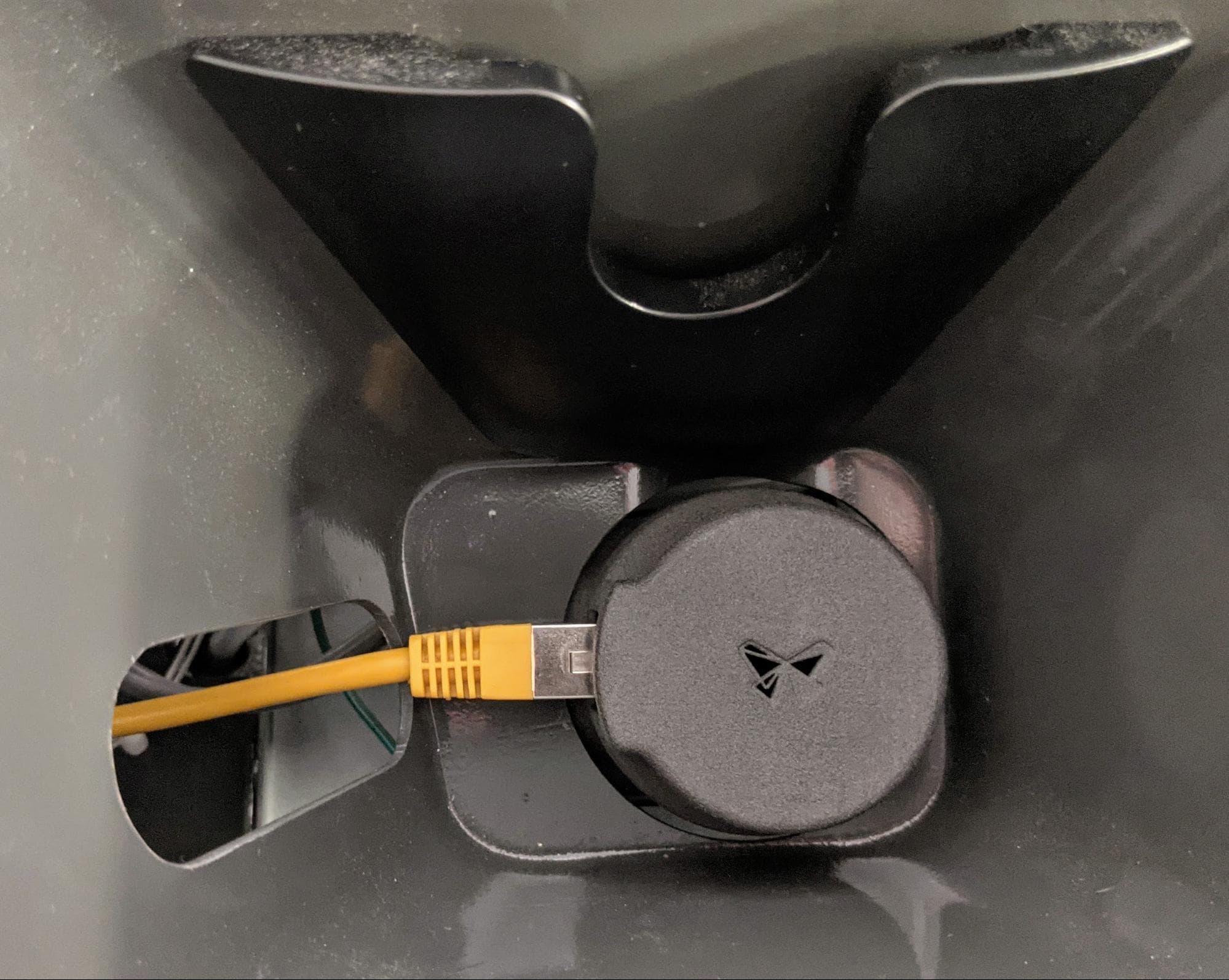
Inspect the IR sensor lens for debris and clean it if necessary. Attach the ethernet cable to the IR sensor, then place the sensor back into its mount.
Reinstalling the top panel
Overview: After installing the new IR sensor flow body, reinstall and secure the top panel.
Step 1: Align the top panel
Lift the top panel and place it on top of the printer. Align the screw holes in the top panel with the corresponding holes in the printer frame.
Step 2: Secure the top panel screws
Thread a 6 mm M4 countersunk screw into each of the 26 marked screw holes in the top panel:
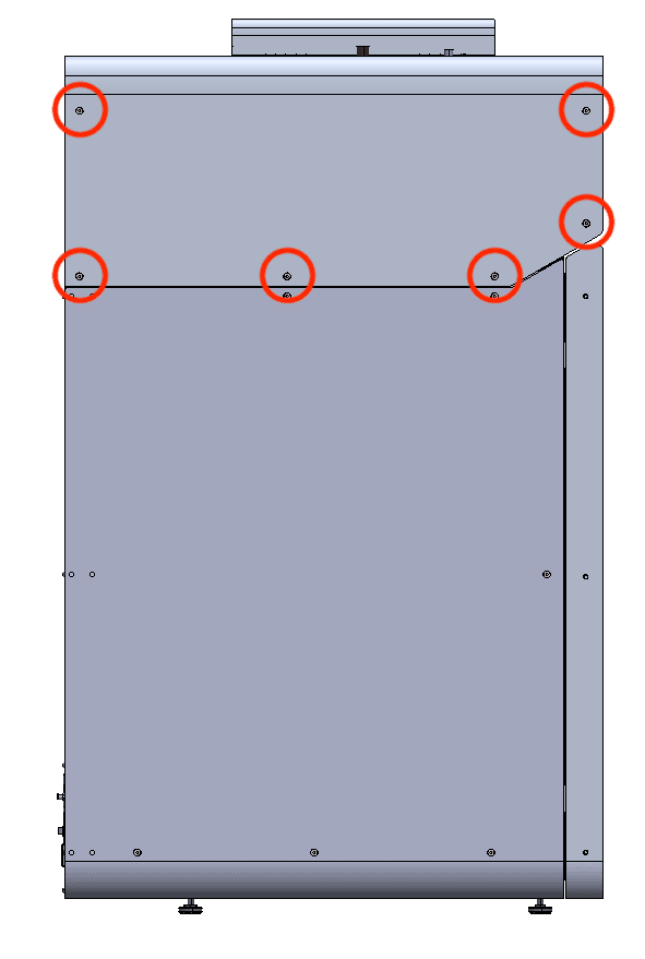
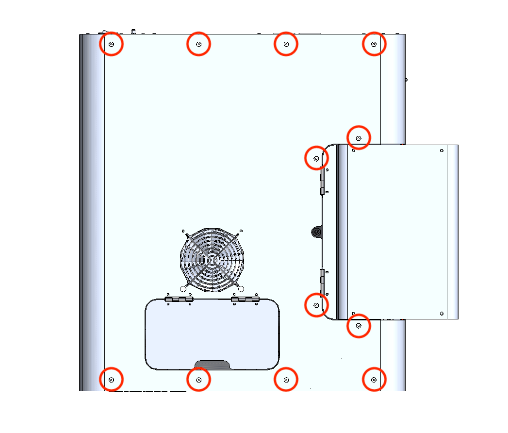
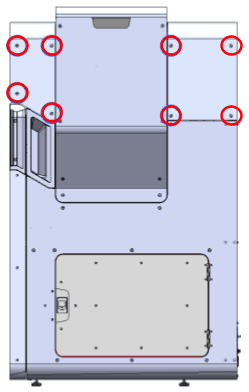
Using a 2.5 mm hex driver, tighten the screws until snug.
Finalizing the repair
Overview: After installing the replacement IR sensor flow body, power on the printer and perform final checks.
Step 1: Power on the printer
Connect the power cable to the printer and the power supply. The printer initializes.
Step 2: Test the repair
Start a print. Monitor the printer to ensure that the print proceeds normally. Contact Formlabs Support or your certified service provider to share the results of the procedure.