
Note:
Depending on the date of manufacture of your machine, the replacement blower fan may look different than the original.

The Fuse Sift has a blower that pulls ambient air through the HEPA filter and exhausts out the back of the machine. If the blower fan is faulty or malfunctioning, the machine will not be able to filter the workspace air effectively.
Use this guide to replace the Fuse Sift blower fan.
Note:
Depending on the date of manufacture of your machine, the replacement blower fan may look different than the original.
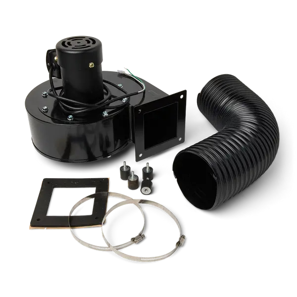
Required Supplies:
Formlabs:
Third-party:
Estimated time: 30–45 minutes
Removing the rear enclosure panel
Overview: Remove the rear enclosure panel to access the blower fan.
Step 1: Unplug the Fuse Sift
Power off the Fuse Sift, then unplug the power cable from the rear panel. Flip the power switch to the ON position and wait five minutes to discharge the power supply, then turn the switch off again.
Danger:
Performing this procedure on the Fuse Sift while it is plugged in increases the risk of electric shock. After disconnecting the power from the Fuse Sift, wait at least five minutes before servicing.
Step 2: Unscrew the Wi-Fi antenna
Remove the Wi-Fi antenna, if present.
Step 3: Remove the rear enclosure panel
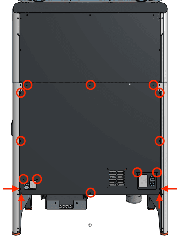
Use a 2.5 mm hex driver to remove the 16 black 8.0 mm M4 screws securing the rear panel to the Fuse Sift. Set the rear enclosure panel aside.
Tip:
Remove the top three screws last to prevent the panel from falling off.
Notice:
The Fuse Sift contains sensitive electronic components. Ground yourself before touching any electronics in the device by using an antistatic wrist band.
Removing the blower fan
Overview: Disconnect and remove the blower fan and duct.
Step 1: Remove the blower fan intake duct
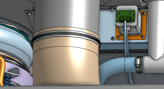
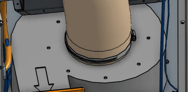
Locate the blower fan, positioned at the bottom-right of the Fuse Sift when facing the back of the machine. A duct connects the blower fan intake to the cavity behind the Fuse Sift HEPA filter. Using a flat head screwdriver, loosen the two hose clamps securing the two ends of the duct. Remove the duct from the Fuse Sift and set it aside for disposal.
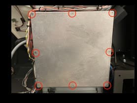
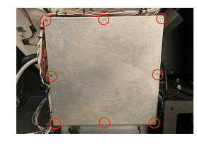
Locate the square motherboard cover on the rear of the machine. Using a #2 Phillips driver, loosen and remove the eight countersunk screws securing the cover onto the motherboard enclosure. Set the screws and cover aside.
Step 3: Disconnect the blower fan cable
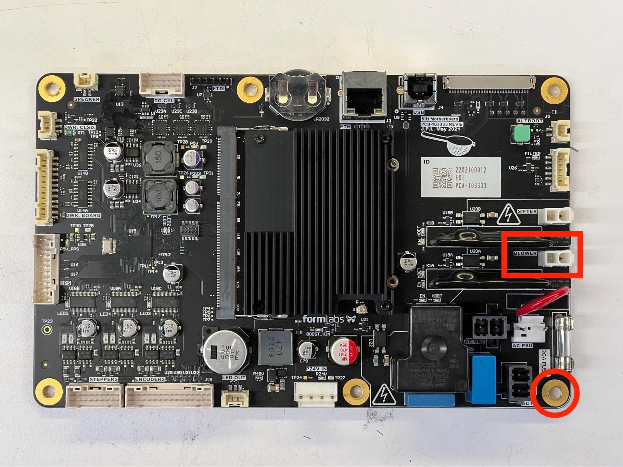
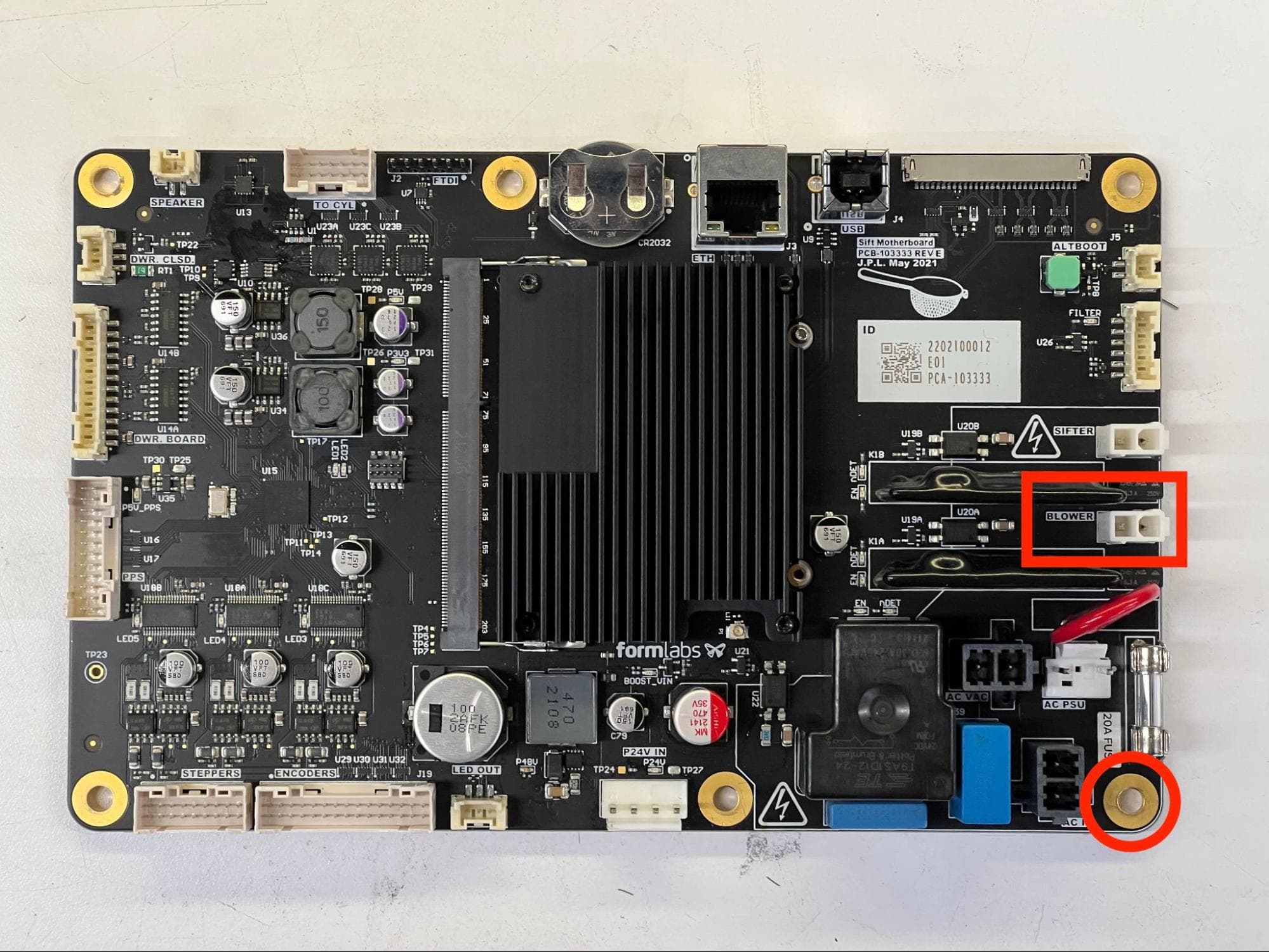
If you have not already, put on an antistatic wristband and connect it to a known ground point. Do not connect the wristband to any surfaces that are powder-coated or painted. Disconnect the blower fan cable from the port on the motherboard labeled BLOWER.
Using a 2.5 mm hex driver, loosen and remove the chrome 10.0 mm M4 screw securing the grounding ring terminal to the bottom-right corner of the motherboard.
Step 4: Separate the blower fan cable from other wires
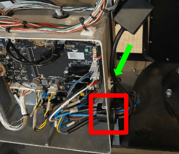
Locate the cord holder passing through the right side of the motherboard enclosure. Squeeze the three retention tabs and push it through to the outside of the enclosure.
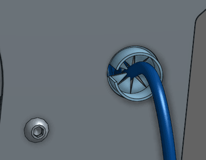
Turn the grommet until the opening faces you. Pry apart the halves of the grommet with a flathead screwdriver. Feed the vibration motor’s cable out of the enclosure, remove the motor cable from the cable holder, then set it aside.
Use a pair of flush cutters to cut the zip tie on the outside of the motherboard enclosure, directly above the cable holder you just removed.
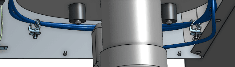
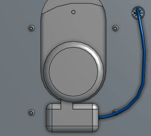
Follow the blower fan cable downwards. Separate it from the cable clamps on the left and right side of the blower fan.
From the bottom of the machine, push the cable guide upwards. Once it is free, pull the blower fan cable out through the opening in the side of the guide. Pull the blower fan cable out of the Fuse Sift through the cable guide’s mounting hole.
The blower fan is secured to the Fuse Sift with four screws on the bottom of the machine. Using a 3 mm hex driver, loosen and remove the four screws. Set the screws aside.
Step 6: Remove the blower fan
Tilt the blower fan up so it clears the panel on which the power port is mounted. Pull the blower fan out the back of the Fuse Sift and set it aside for disposal with electronic waste.
Installing the replacement blower fan
Overview: Mount and secure the new Fuse Sift blower fan and duct.
Step 1: Prepare the blower fan
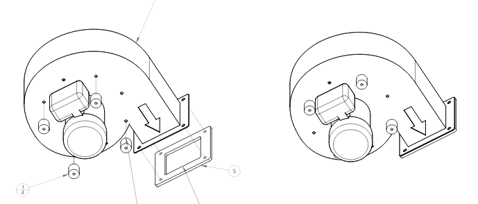
Remove the blower fan and its accessories for its packaging. Thread one of the included vibration damping mounts into each of the four screw holes in the bottom of the blower fan.
Inspect the included blower fan gasket for any contamination or debris. Use a clean paper towel to wipe it clean. One side of the replacement gasket has adhesive pre-applied. Peel any protective layers off of the gasket and adhere it to the blower fan exhaust duct. Make sure that the gasket does not extend into the duct opening.
Step 2: Mount the blower fan
Orient the blower fan with the vibration damping mounts facing down and the rectangular exhaust duct facing you. Insert the blower fan into the back of the Fuse Sift above the power port. Tilt the back of the blower fan down so it tucks under the build chamber enclosure. Lower the blower fan into place once it clears the power port. Check that the screw holes in the vibration damping mounts align with the corresponding holes in the bottom of the Fuse Sift.
Thread one mounting screw into each of the four screw holes in the blower fan vibration damping mounts. Using a 3 mm hex driver, tighten until snug.
Step 4: Route the blower fan cable
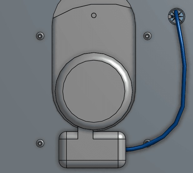
Feed the blower fan cable up through the hole in the bottom of the Fuse Sift. Insert the cable into the toothed cable guide, then push the guide down into the hole.
Route the cable around the back of the blower fan. Secure the cable with the two cable clamps adjacent to the blower fan.
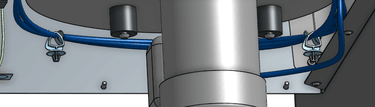
Bundle the blower fan cable with the other cables in the cord holder. Squeeze the cord holder shut. Route the blower fan cable connector into the motherboard enclosure, then press the cord holder into its hole until retention tabs click into place.
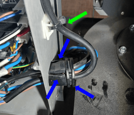
Step 5: Connect the blower fan cable
Connect the blower fan cable to the socket on the motherboard labeled BLOWER. The socket is very fragile, so check that the cable connector is oriented correctly and do not force it into place.
Step 6: Reconnect the grounding ring terminal
Resecure the grounding ring terminal to the bottom-right corner of the motherboard using its chrome 10.0 mm M4 screw. Using a 2.5 mm hex driver, tighten until snug.
Place the motherboard cover onto the motherboard enclosure, aligning the screw holes in the cover with the corresponding one around the edge of the enclosure. Thread one mounting screw into each of the eight screw holes, then use a #2 Phillips screwdriver to tighten until snug.
Step 8: Mount and secure the blower fan intake duct
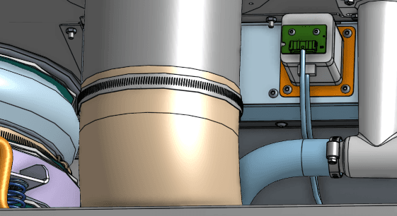
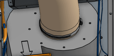
Using a flat head screwdriver, loosen the two included hose clamps. Slide the hose clamps onto the ends of the included duct. Mount one end of the duct onto the blower fan inlet (on the top of the fan) and the other end onto the flange extending downwards from the filter cabinet. Using the flat head screwdriver, tighten the hose clamps until the duct is secure at both ends.
Reinstalling the rear enclosure panel
Overview: Mount and secure the rear enclosure panel after installing the new blower fan.
Step 1: Prepare the rear panel retention screws
Apply a small amount of Loctite 243 or other similar threadlocker to each of the 16 black 8.0 mm M4 button screws that secure the rear panel to the Fuse Sift.
Step 2: Mount the rear panel
Mount the rear panel onto the Fuse Sift.
Step 3: Secure the rear panel
Thread one 8.0 mm M4 button screw into each of the 16 screw holes in the rear panel. Use a 2.5 mm hex driver to tighten until snug.
Tip:
Start with the top three screws to hold the panel in place while you thread and tighten the remaining screws.
Finalizing the repair
Overview: After installing the new blower fan, power on the Fuse Sift and test its functions.
Step 1: Power on the fuse sift
Reconnect the Fuse Sift to its power source. Flip the power switch to the ON position.
Step 2: Test the machine
Activate the Fuse Sift fan and make sure it turns on and operates as expected. Contact Formlabs Support or your certified service provider to share the results of the procedure.