Changing the hardness of parts printed in TPU 90A Powder Using the PreForm Print Settings Editor

TPU 90A Powder is a fantastic material for printing high-quality elastomeric parts with the Fuse 1+ 30W, but the high hardness of the base powder makes it an ineffective choice for certain applications. Having a different material for each hardness would be impractical for an efficient workflow on a single printer.

Using the PreForm Print Settings Editor, you can modify the hardness of TPU 90A Powder. For many print applications, modifying the settings will create high-quality prints with the exact hardness desired. Unlike changing materials, changing print settings does not require any additional cleaning or modification between prints—you can print parts with different hardnesses back to back, all within the same workflow. However, there are risks associated with using the Print Settings Editor which may cause certain parts to fail or features to not resolve as they would at a 90A hardness.

There are two main settings that can be used to control the hardness of parts printed with TPU 90A Powder:

SettingEffect
Fill Laser Power

Lower laser powers do not sinter the TPU together as densely, resulting in a softer material.

If the Fill Laser Power is too low, the part may not sinter at all and features will not resolve.

Fill Hatch Spacing

A wider spacing of the laser scans undersinter the material, allowing it to be much softer.

If the Fill Hatch Spacing is too wide, there will be very visible defects on the surface from the spacing and pieces may peel off of the part.

Selecting and modifying the print settings

Note:

The analysis below and the testing data provided at the end of this article are valid for Fuse 1+ 30W printers. While this technique also works with Fuse 1 printers, the parameter changes and resulting part hardness will likely be different and require additional testing.

A range of Fill Laser Power and Fill Hatch Spacing values will produce usable parts at different hardnesses:

  • Fill Laser Power: 15,000–28,500 mW
  • Fill Hatch Spacing: 0.12–0.45 mm

Notice:

Do not set the Fill Laser Power higher than 28,500 mW. Smoking from the lasered powder can damage optical components in the printer.

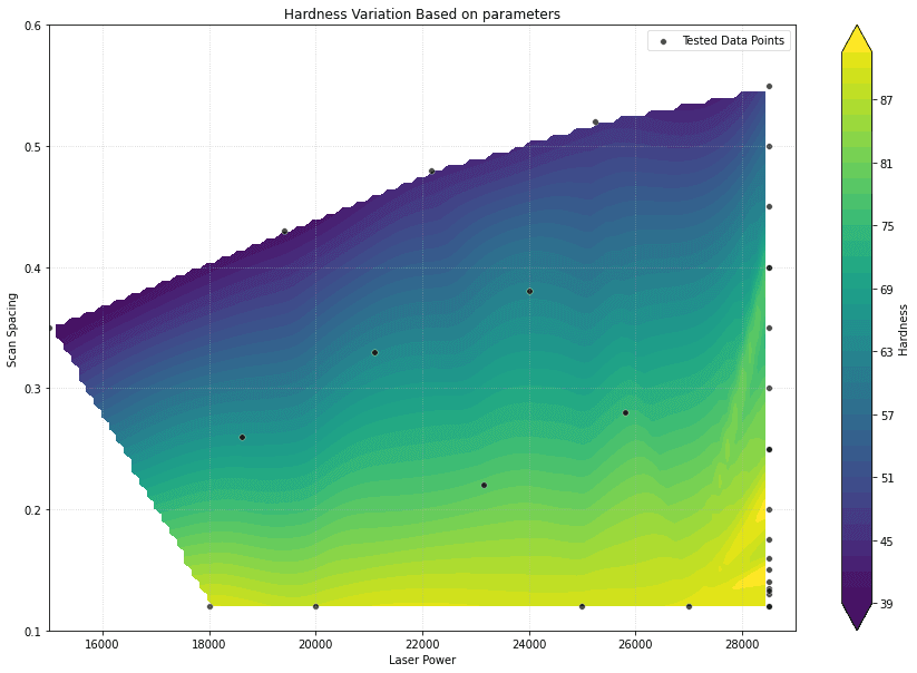
The result of modifying these settings can be seen here. The raw data used to create this graph is given below.

Part hardness vs. Fill Hatch Spacing and Fill Laser Power

Part hardness vs. Fill Hatch Spacing and Fill Laser Power

Shore hardnesses of as low as 38 Shore A were achieved during testing. In general, Fill Hatch Spacing plays a much larger role in determining hardness, with Fill Laser Power amplifying the effect. For example, for a hardness of 60 Shore A, a good starting point would be a Fill Hatch Spacing of 0.35 mm and a Fill Laser Power of 21,000 mW.

Follow the instructions in Using the PreForm Print Settings Editor (SLS) to modify the print settings.

Sample print setting downloads

Here are sample print settings for achieving 40A, 50A, 60A, and 80A Shore hardness using TPU 90A Powder. Use these as a starting point when developing your own print settings, along with the graph above and testing data below.

Effect of Fill Hatch Spacing on part quality

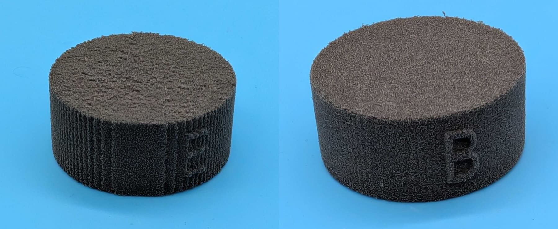
At a Fill Hatch Spacing of 0.45 mm, there are visible surface effects from the hatch spacing, but features still typically resolve. Thick parts may still print with wider spacings, but they may have significant defects, as shown below. Formlabs does not recommend printing thin parts with greater than 0.45 mm spacing.


Parts printed in TPU 90A Powder with 0.55 and 0.26 mm Fill Hatch Spacing

Left: a part printed with a Fill Hatch Spacing of 0.55 mm
Right: a part of roughly the same hardness but with a Fill Hatch Spacing of 0.26 mm
Both of these parts were printed with the flat surface parallel to the print bed, so the effect reminiscent of layer lines is purely a result of the scan spacing. The surface texture is also dramatically worse at the top of the part printed with the wider spacing.

Effect of hardness changes on mechanical properties

As the Shore hardness of a part decreases, the bulk density also decreases, with the part becoming more of a foam at the microscopic level. This impacts mechanical properties other than hardness as well as the watertightness of the parts. If you are planning on using the part in an application that requires a certain amount of mechanical resistance and wear, make sure to test the part fully.

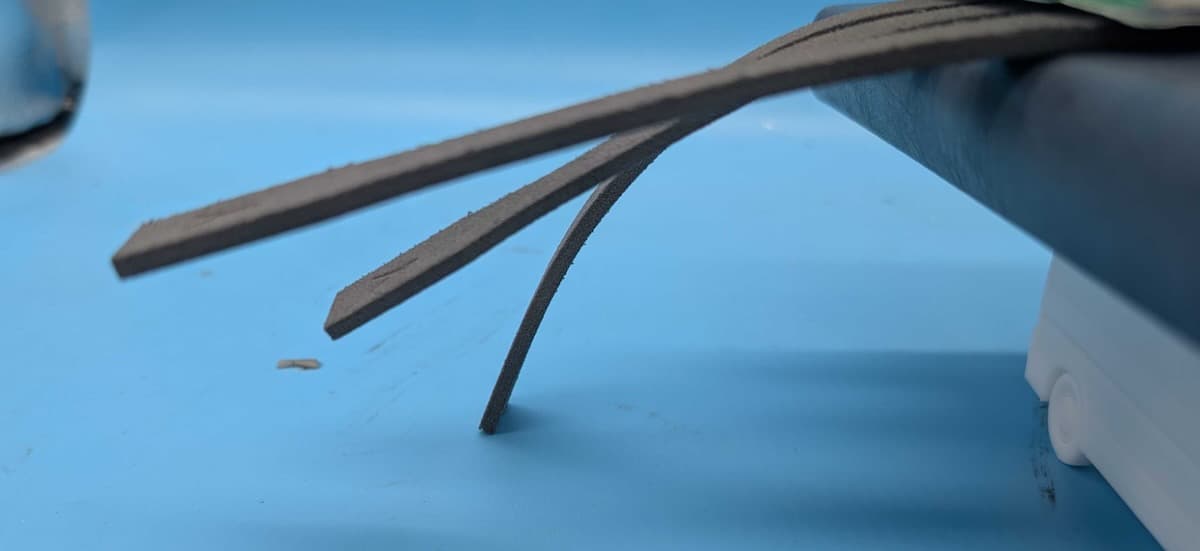
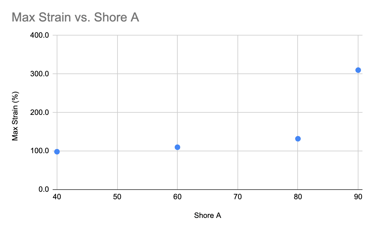
Because the material is only partially sintered, there is a sharp dropoff in many properties, particularly elongation at break (EAB), ultimate tensile strength (UTS), and stiffness. This is easy to see on long strips like the tensile bars in this image. The rearmost bar has a Shore hardness of 40A, the middle bar has a hardness of 60A, and the front bar has a hardness of 80A. The 40A sample flexes down to the work surface under its own weight.

Tensile bars at different hardnesses

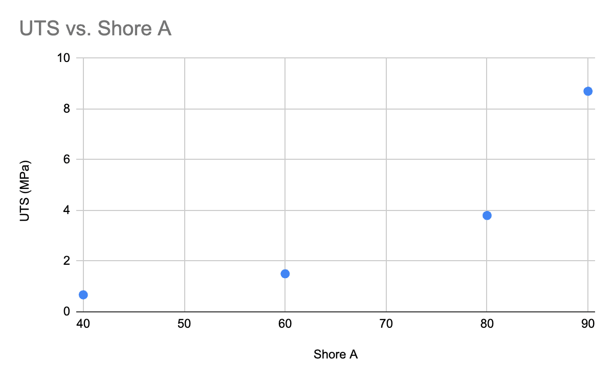
To quantify this effect more precisely, see the graphs below. Reducing the hardness from 90A to 80A also reduces the UTS and maximum strain of the parts by over 50%. This makes it more likely for parts to tear during depowdering, damaging fine features.

UTS vs. Shore A hardness for parts printed in TPU 90A Powder
Max strain vs. Shore A hardness for parts printed in TPU 90A Powder

Caveats

  • As hardness decreases, the risk of print issues increases.
  • Since the hardness of 90A is the hardness of the bulk material, it is not possible to significantly increase the hardness beyond 90A.
  • Bed temperature variations occur from printer to printer and within a given build. These can have an effect on the resulting hardness of the part. In general, expect a +/- 5 Shore A variation throughout a given build. The variation will be smaller the closer the hardness is to that of the bulk material (90A).

Raw testing data

The table below lists raw data from Formlabs testing on the effect of Fill Laser Power and Fill Hatch Spacing on Shore hardness. Reference this data when developing your own print settings.

Fill Laser Power Fill Hatch Spacing Hardness
15000 0.35 37.7
18000 0.12 90.1
18625 0.26 66.3
19400 0.43 40.4
20000 0.12 88.5
21100 0.33 62.7
22160 0.48 43.6
23150 0.22 78.6
24000 0.38 62.3
25000 0.12 89.8
25250 0.52 45.3
25800 0.28 74.9
27000 0.12 90.6
28500 0.12 89.8
28500 0.12 91.4
28500 0.13 90.7
28500 0.1325 89.5
28500 0.135 91.1
28500 0.14 91.6
28500 0.15 93.2
28500 0.16 89.1
28500 0.175 87.7
28500 0.2 92.2
28500 0.25 83.6
28500 0.25 80.4
28500 0.3 80.2
28500 0.35 73.7
28500 0.4 74.2
28500 0.4 77.7
28500 0.45 63.8
28500 0.5 57.1
28500 0.55 49.5