WHITE PAPER
Formlabs Logo

Checking and securing the Fuse 1 generation build chamber piston arm screws

Checking and securing the Fuse 1 generation build chamber piston arm screws

Over the course of a print, the Fuse 1 generation build chamber's print bed lowers as more powder is deposited and more layers are printed. If any part of the mechanism that drives the print bed is loose, the print bed and powder cake could move laterally, leading to print defects or failures.

Use this guide to check and resecure the build chamber piston arm screws.

Checking the build chamber piston arm

Required supplies:

  • Torque driver with hex bits
  • 2.0 mm hex driver or Allen key (flat-end)
  • 2.5 mm hex driver or Allen key (flat-end)
  • 3.0 mm hex driver or Allen key (flat-end)
  • 120.0 mm machinist square
  • Putty knife
  • Compliant vacuum with static dissipative components, such as a Class II, Division 2 vacuum
  • Vacuum brush tools
  • Safety glasses
  • Loctite 246 or equivalent threadlocker
  • Nonreactive nitrile gloves
  • N95 or better respirator
  • Acetone
  • Ethanol
  • Non-abrasive lint-free wipes
  • Polyester or cotton swabs
Estimated time: 45–60 minutes

Danger:

Read and follow all safety instructions and warnings in the operator manual. Replacement with incorrect parts can lead to burns, shock, fire, or explosion. Dispose of all parts in accordance with local regulations.

Warning:

Do not perform this procedure if the printer was printing less than six hours prior. Failure to do so may result in serious burns. Allow the print enclosure to cool to room temperature before touching or inspecting any Fuse 1 components.

Removing the print bed

Overview: Empty the build chamber and remove the print bed to begin accessing the piston arm screws.

Step 1: Prepare the build chamber

Put on appropriate personal protective equipment (PPE) for handling the powder in the build chamber.

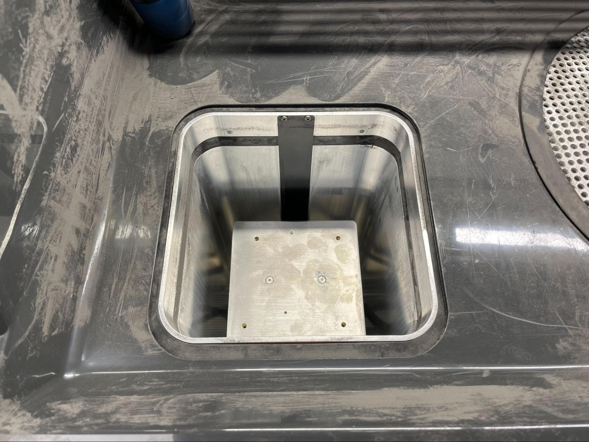
If your build chamber is empty, make sure the print bed is in its highest position. You can use the control panel on the Fuse Sift or tap Maintenance > Move Motors on the printer touchscreen to control the print bed position.

If your build chamber is not empty, insert it into a Fuse Sift, raise the print bed, and remove the powder cake.

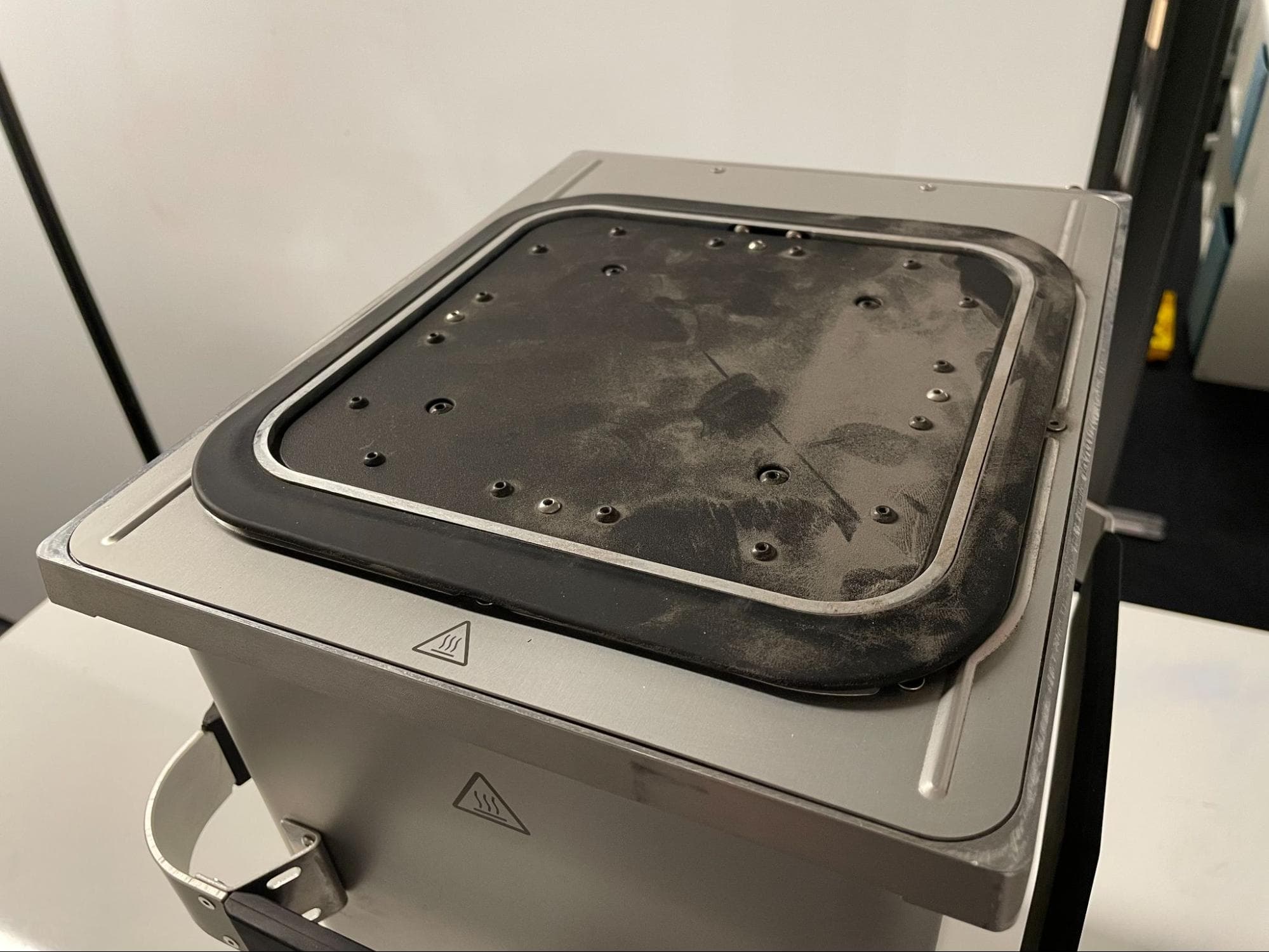
Remove the build chamber from the printer or Fuse Sift, place it on a flat, clean work surface, and vacuum or brush off any remaining powder on the top surface of the build chamber.

Remove the print bed

Step 2: Remove the print bed mounting screws

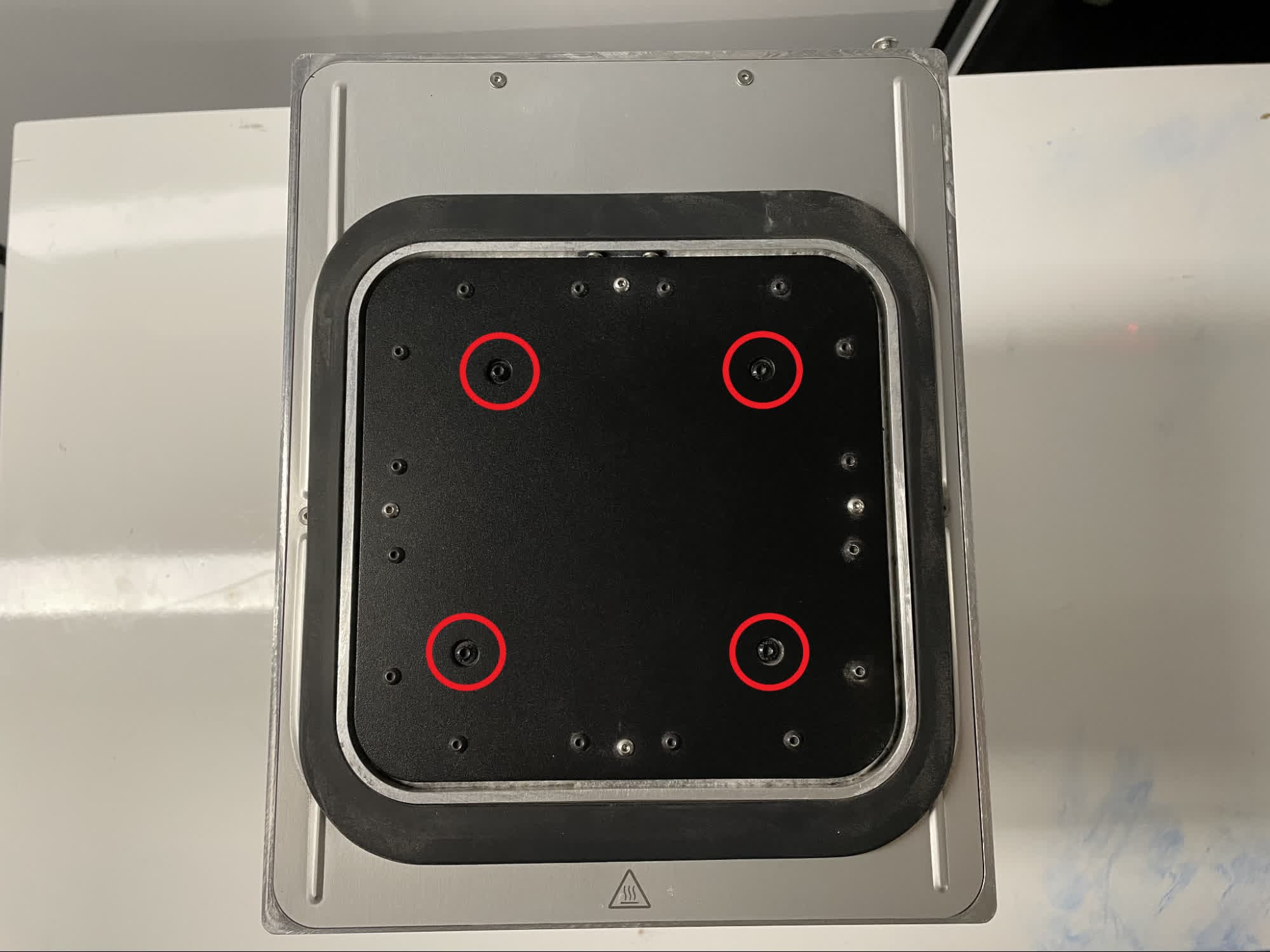
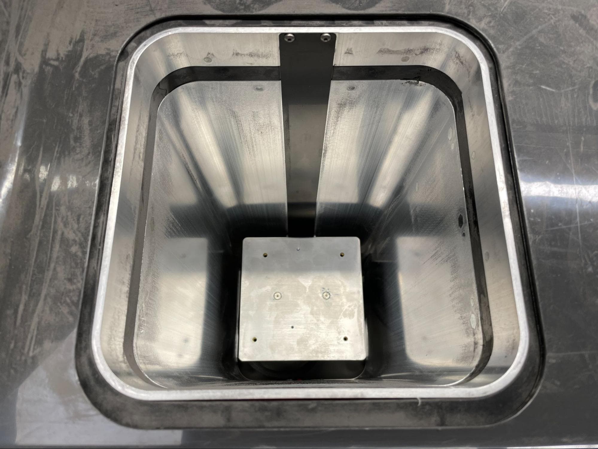
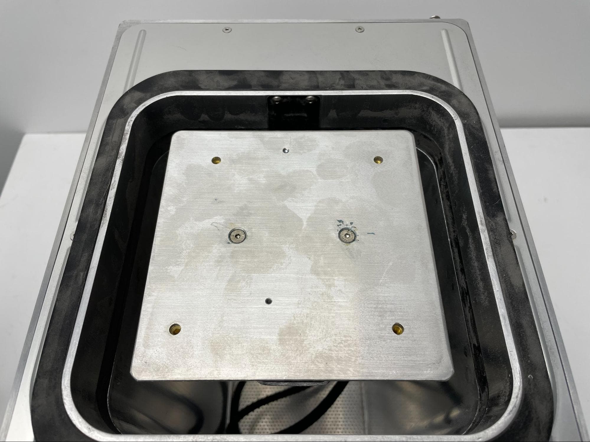
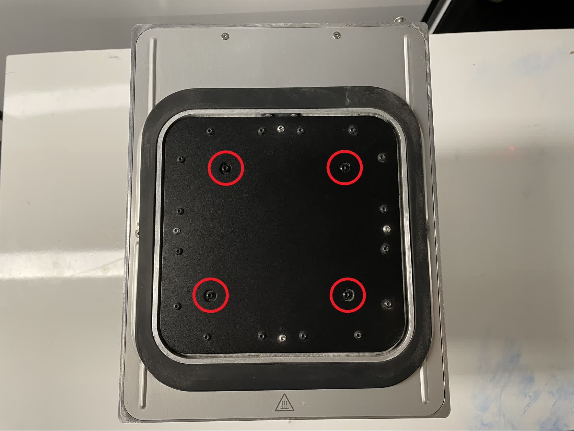
Using a 2.5 mm hex driver, loosen and remove the four 12.0 mm M4 button head screws securing the print bed to the build chamber piston. Set the screws aside.

Remove the print bed

Step 3: Remove the print bed

Remove the print bed

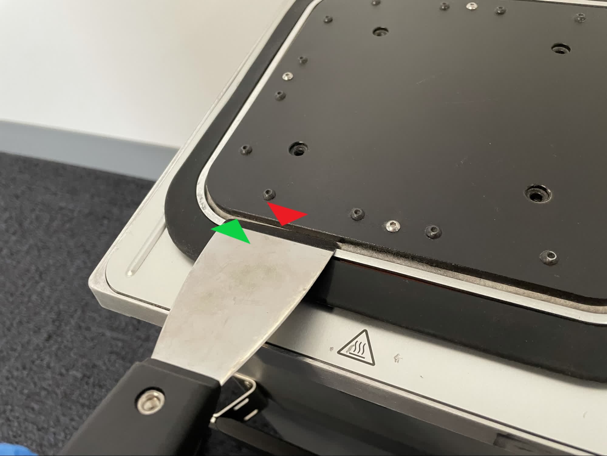
Carefully wedge a putty knife into the gap between bottom of the print bed and the white felt seal to lift an edge of the print bed up. Do not force the putty knife into the gap or use a slotted screwdriver, as either method will damage the inner build chamber wall.

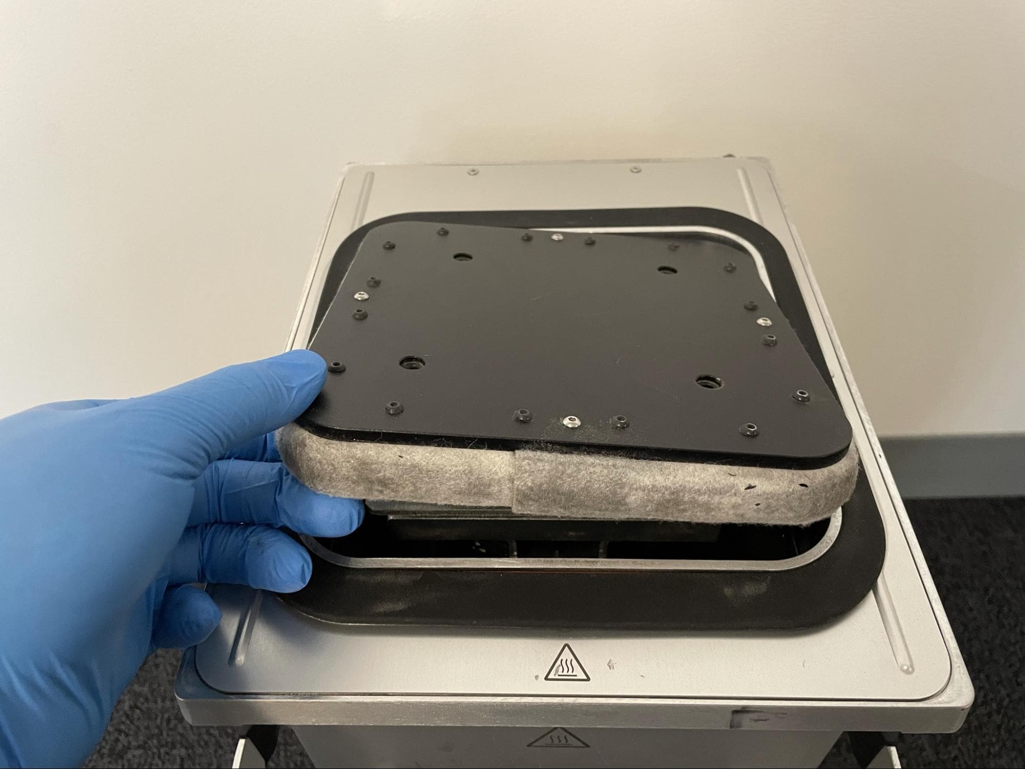
Rotate the entire build chamber 90° and repeat. Continue rotating the build chamber and wedging each edge of the print bed upwards until you can grasp and pick up the print bed by hand.

Remove the print bed from the build chamber and set it aside.

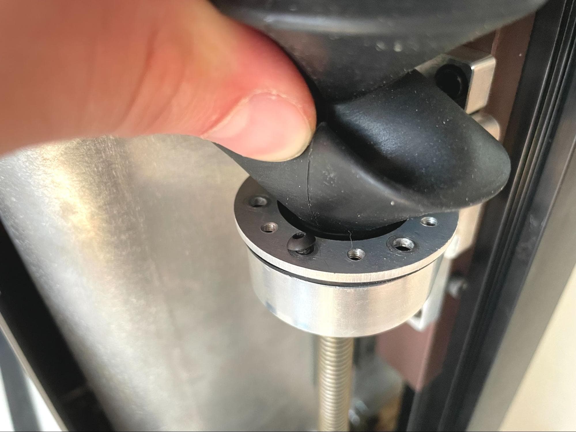
Step 4: Check the piston arm for play

Touch the plate the print bed was mounted on and check whether the it can move or tip forward and backward with minimal effort. If it moves easily, continue. If it does not move easily, skip to the section on checking the heater place spacer screws.

Removing the rear enclosure shell

Overview: Remove the build chamber's rear enclosure shell to access the piston arm screws.

Step 1: Reposition the build chamber piston

Reinsert the build chamber into your printer or Fuse Sift. Use the machine to lower the piston top to about halfway down the build chamber. You can use the control panel on the Fuse Sift or tap Maintenance > Move Motors on the printer touchscreen to control the piston top position, as you did when the print bed was still installed.

Once the piston is in position, remove the build chamber from the printer or Fuse Sift.

Reposition the piston (1 of 3)

Step 2: Remove the build chamber handle mounting screws

Remove the rear enclosure shell

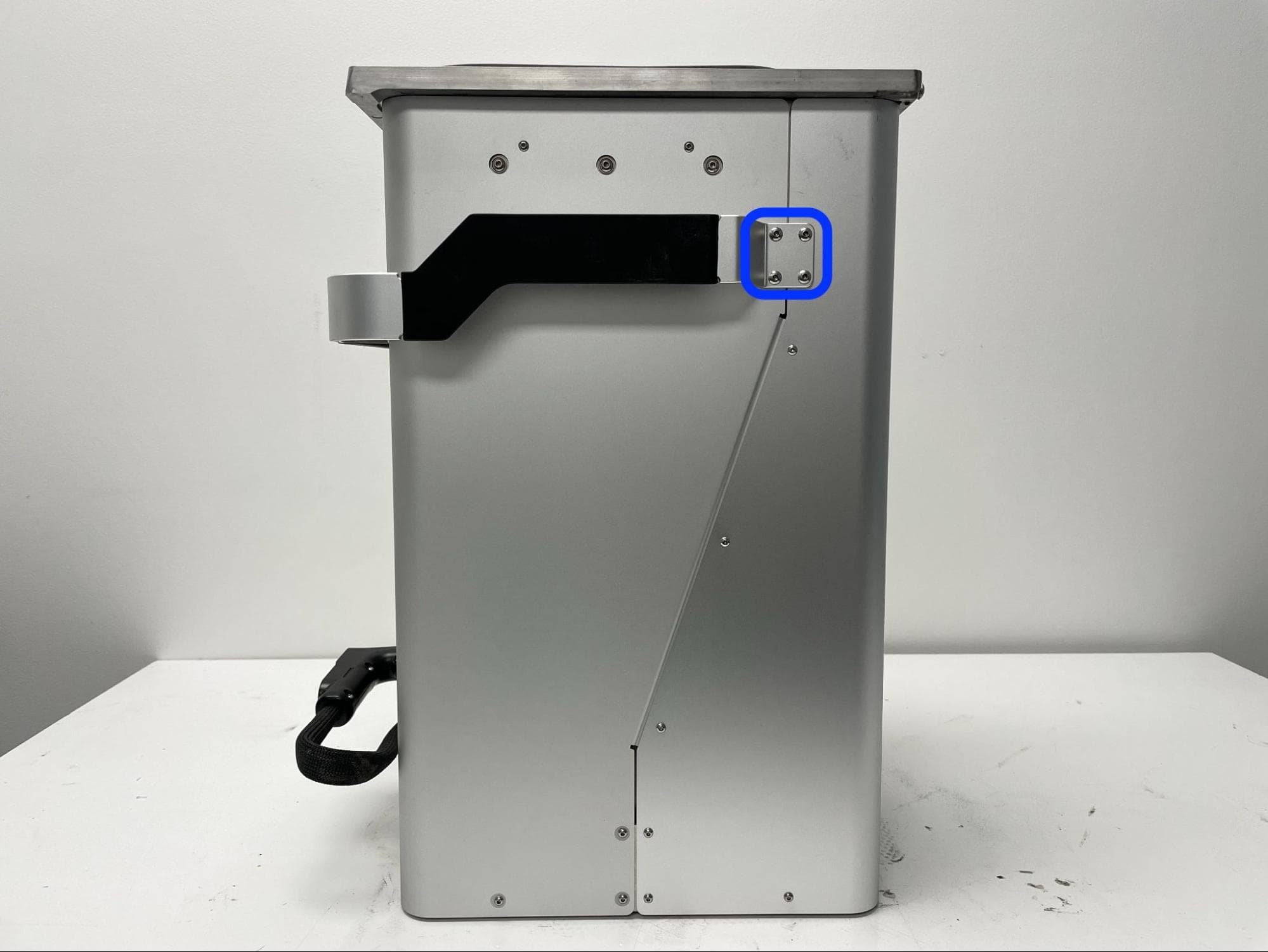
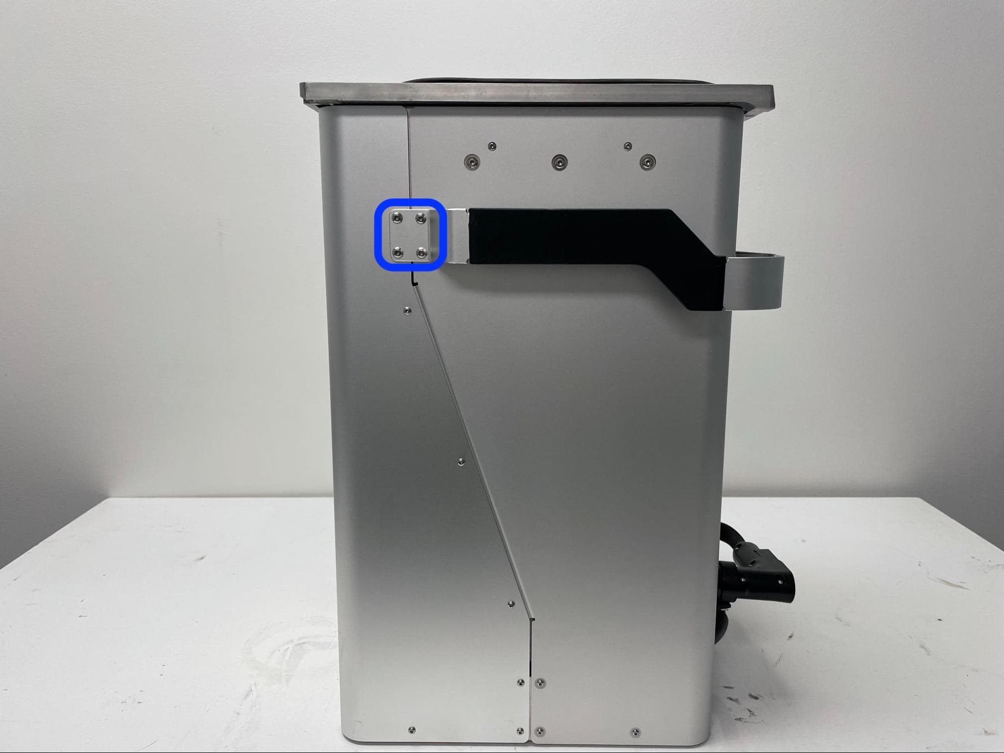
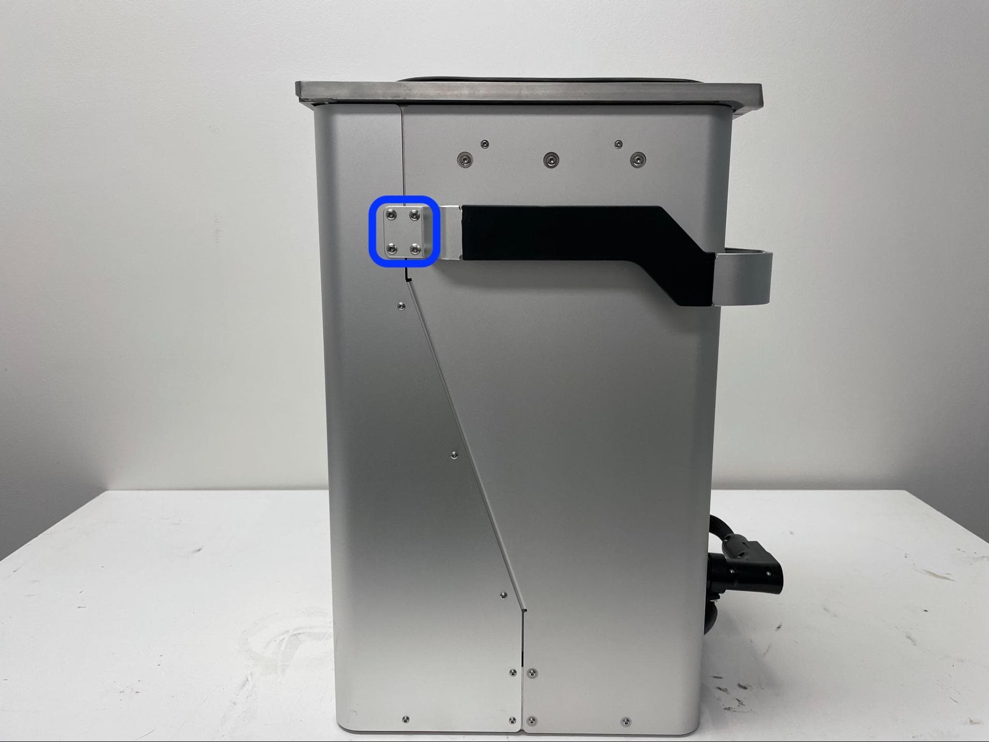
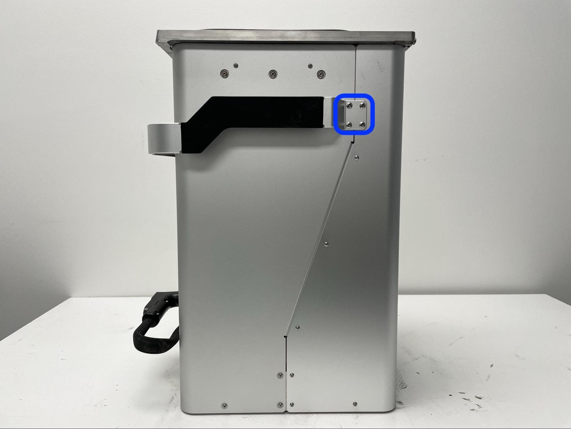
Use a 2.5 mm hex driver to loosen and remove the eight 10.0 mm chrome M4 button screws securing the handle ends to the build chamber. Set the screws aside.

Step 3: Remove the rear enclosure shell mounting screws

Remove the rear enclosure shell

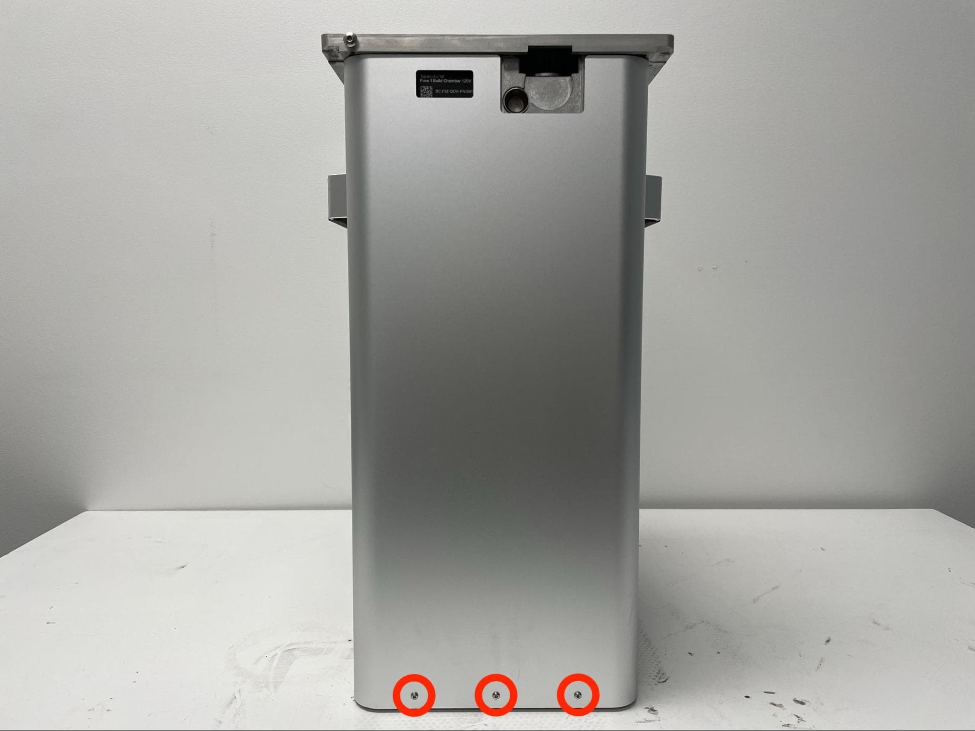
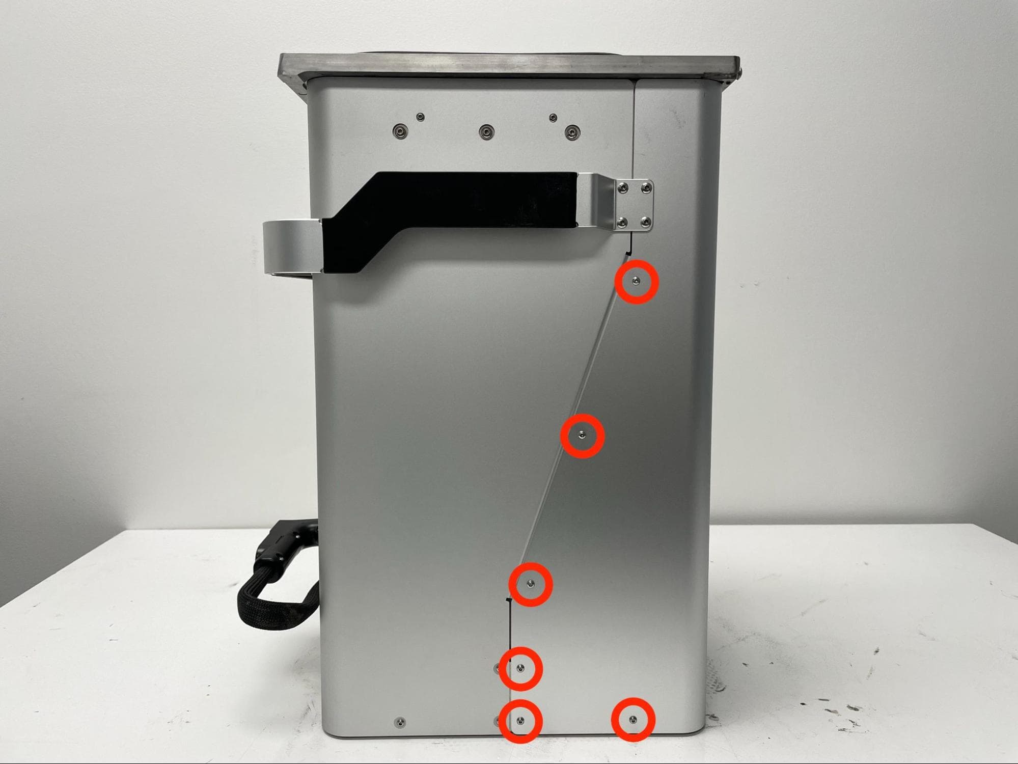
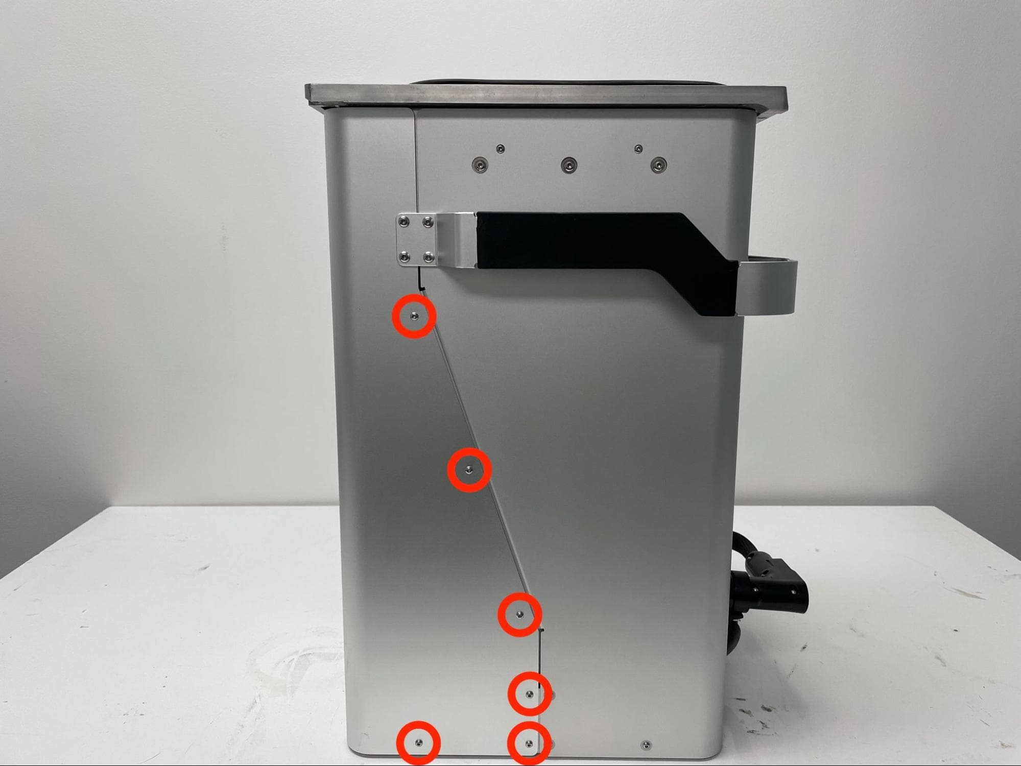
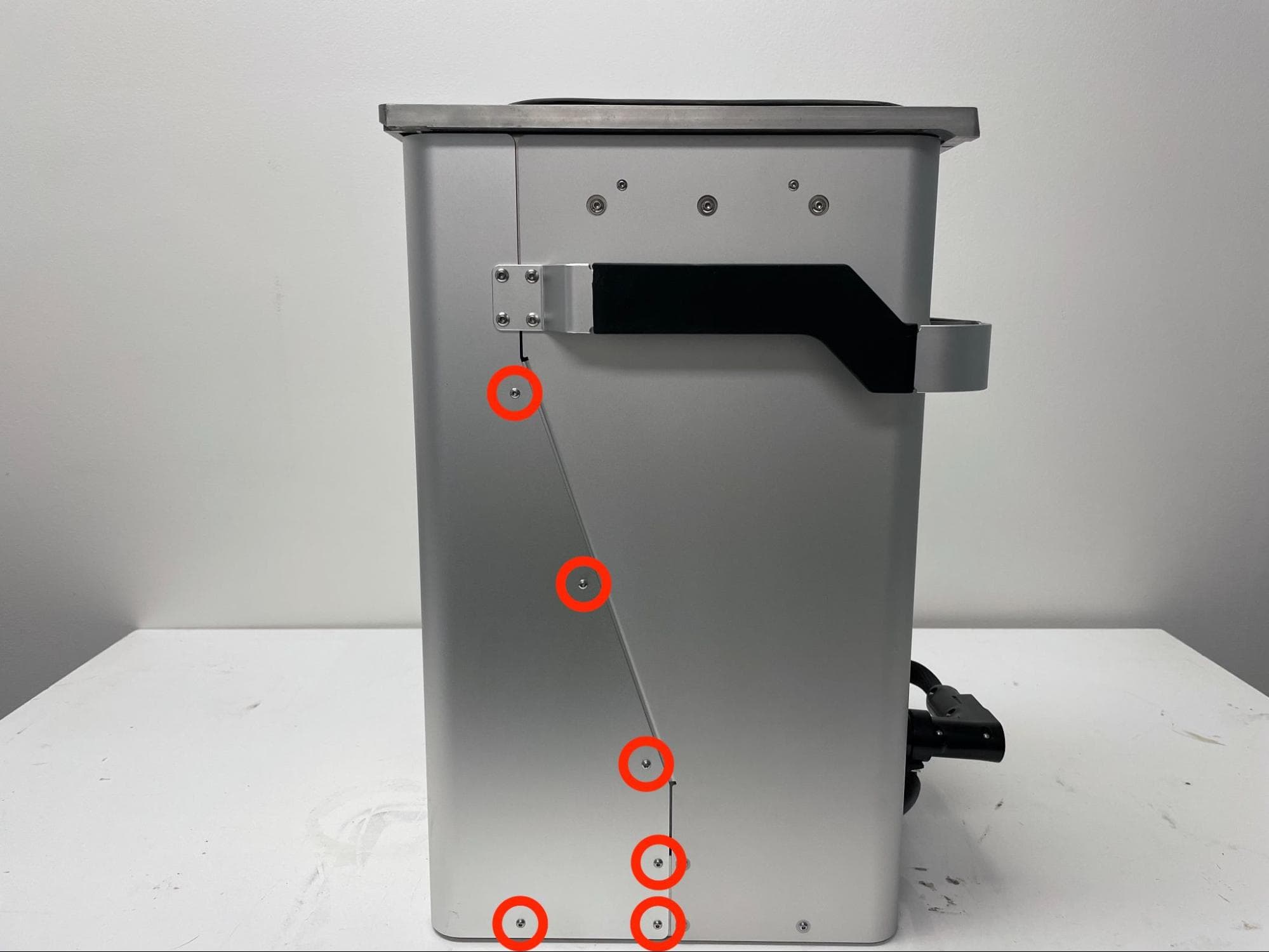
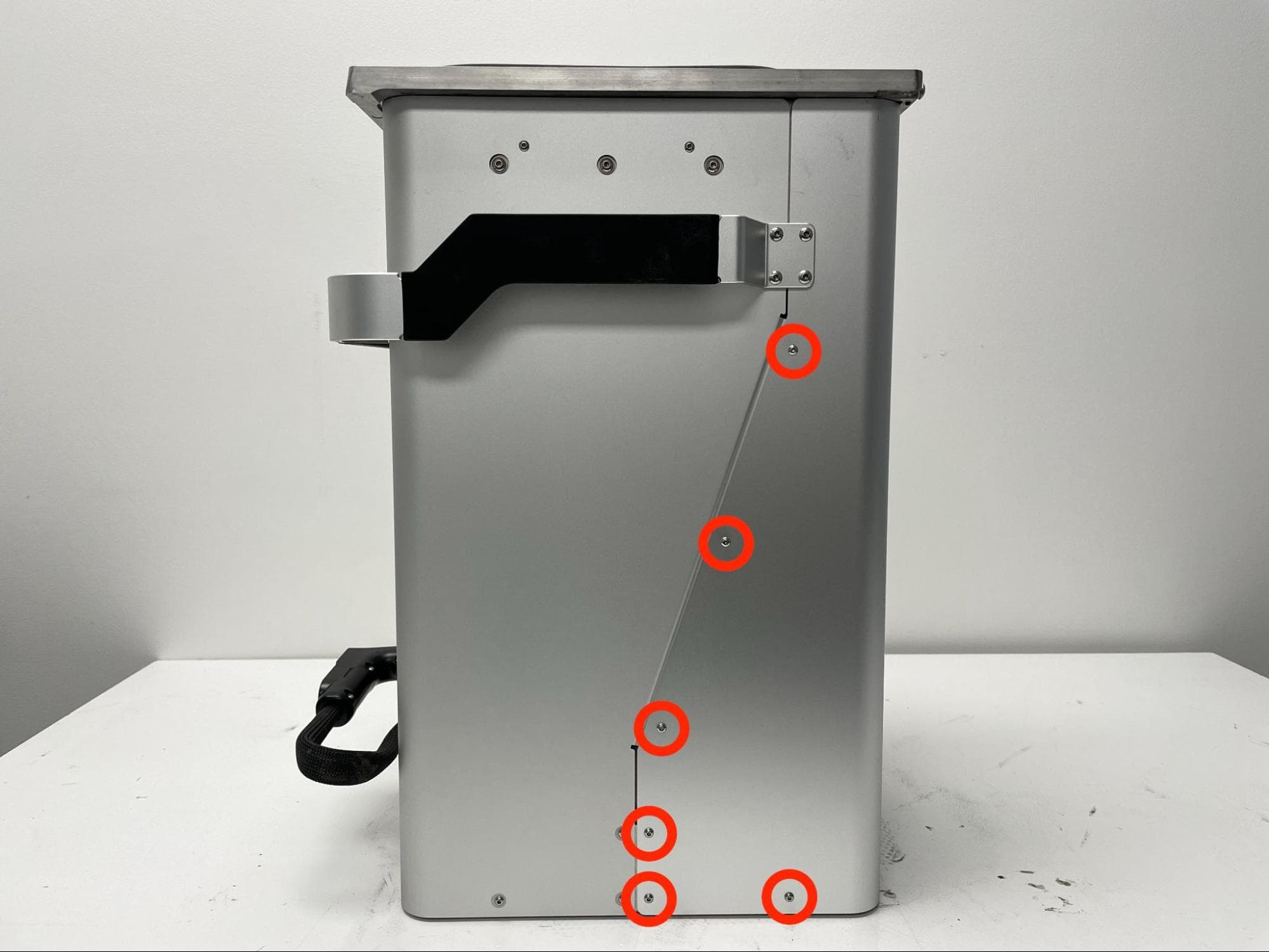
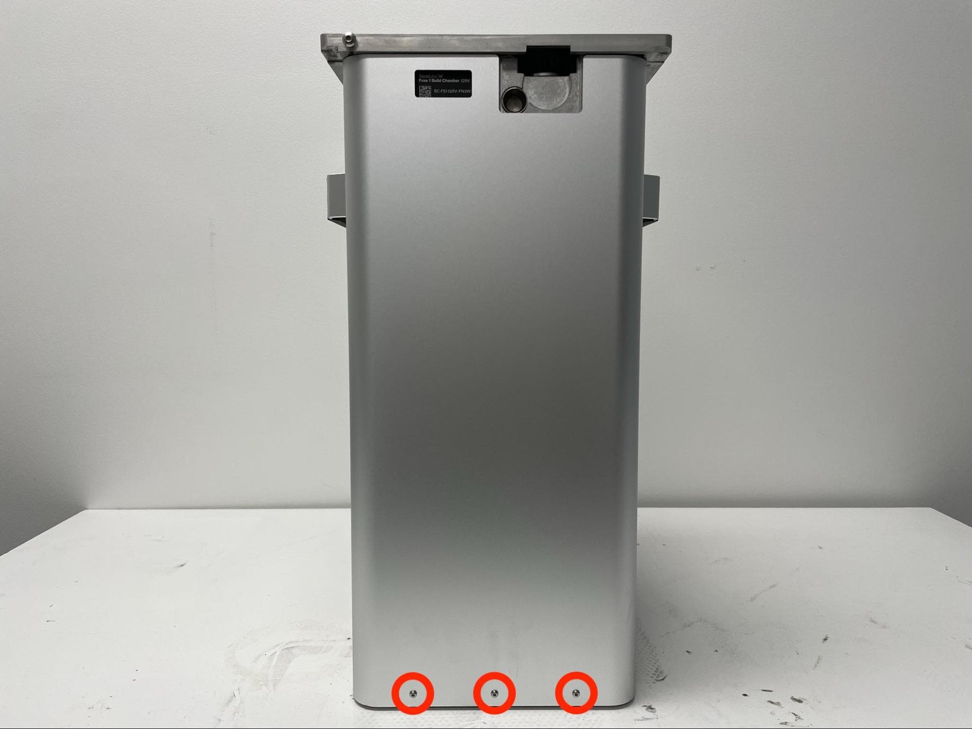
The rear enclosure shell is secured to the build chamber frame using 15 6.0 mm chrome M3 button head screws: six on the left side, six on the right side, and three on the back. Using a 2.0 mm hex driver, loosen and remove the 15 screws. Set the screws aside. Use a 2.0 mm hex driver to remove the 15X 6.0 mm chrome M3 button screws (6X on each side, 3X on the back) securing the rear enclosure shell to the build chamber.

Step 4: Remove the rear enclosure shell

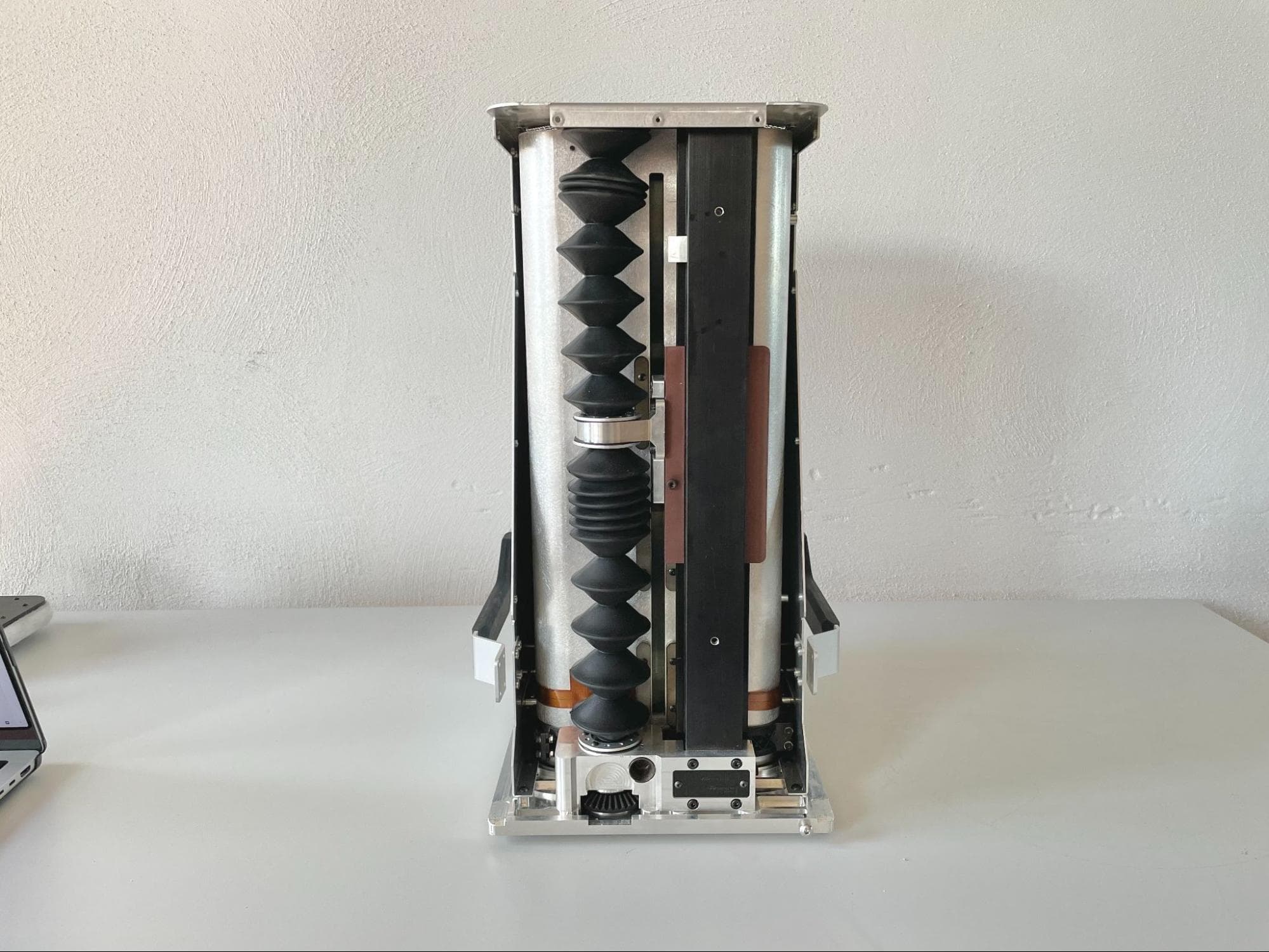
Separate the rear enclosure shell from the build chamber and set it aside.

Checking and securing the carriage screws

Overview: Apply threadlocker to the screws securing the carriage to the lead nut mount.

Step 1: Prepare the build chamber

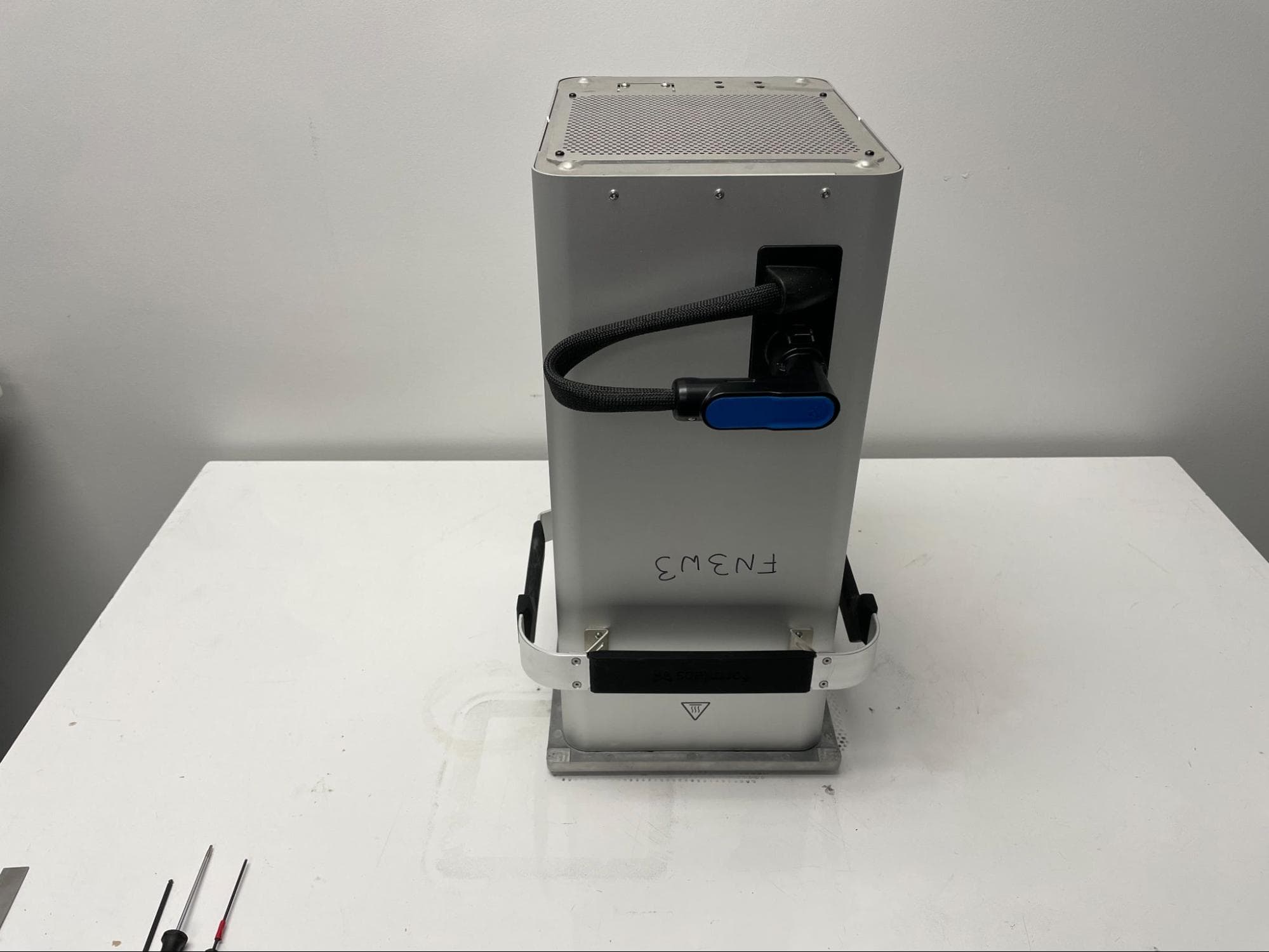
Remove the plug from the silicone holster and rest it next to the build chamber. Carefully lay the build chamber down on its front face. Do not pick up the build chamber by its handle while the rear shell is removed.

Check the carriage screws

Step 2: Separate the bellows from the lead nut mount

Check the carriage screws

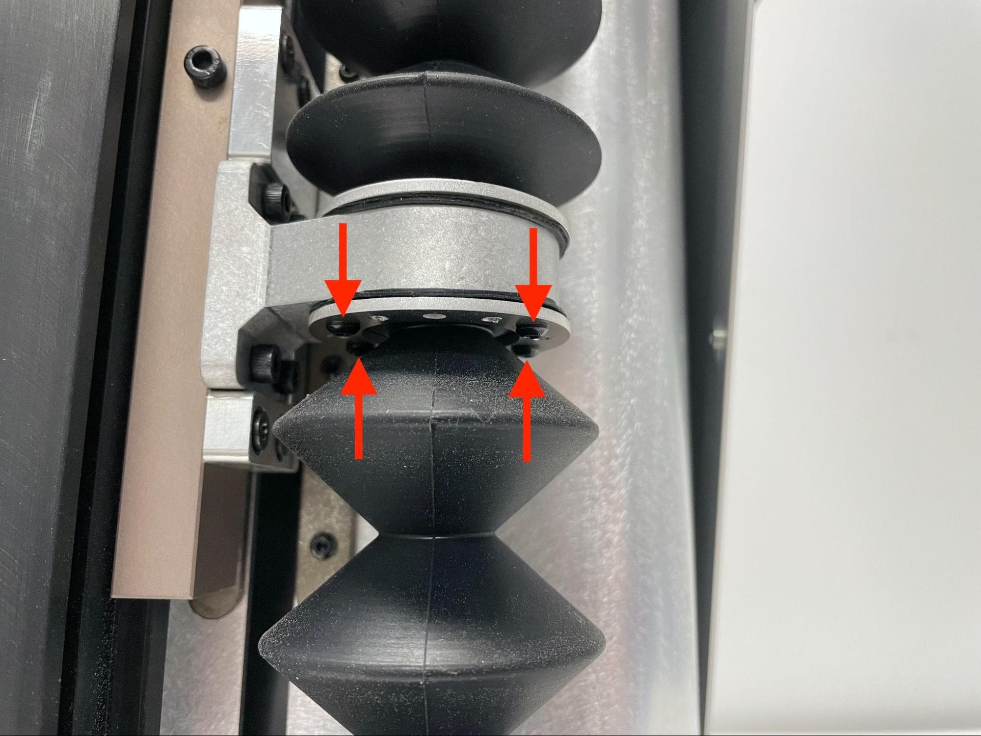
Use a 2.0 mm Allen key to remove the eight 6.0 mm M3 button head screws securing both bellows to the lead nut mount. Set the screws aside.

Step 3: Collapse the bellows

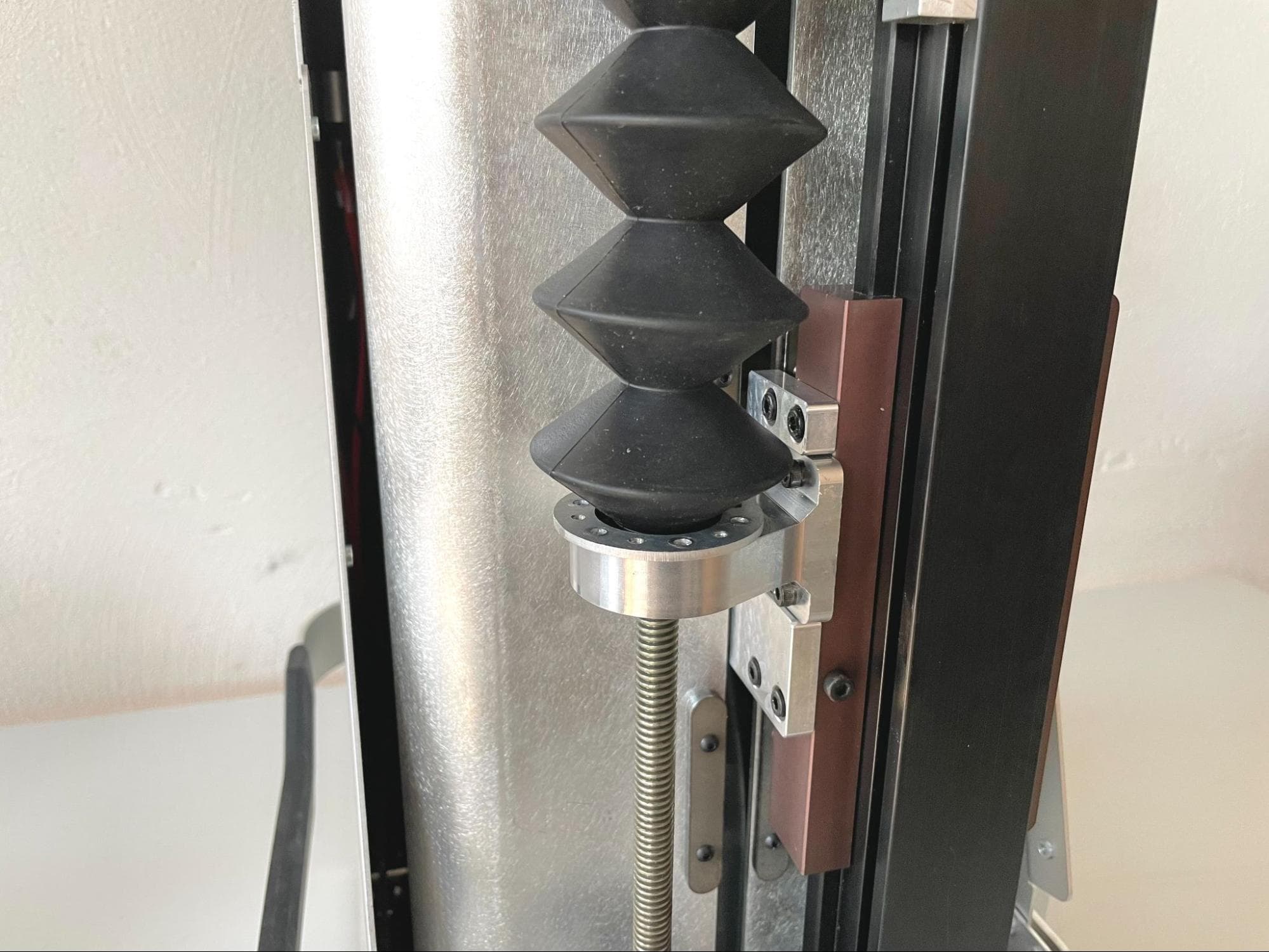
Collapse both bellows away from the lead nut mount to reveal a set of eight 10.0 mm M4 socket head screws.

Check the carriage screws

Step 4: Secure the lead nut mount screws

Check the carriage screws

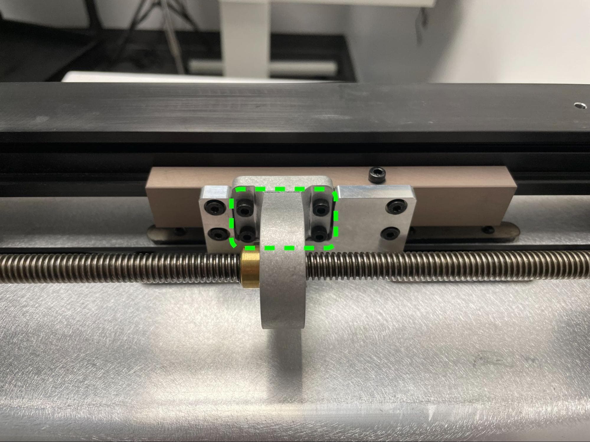
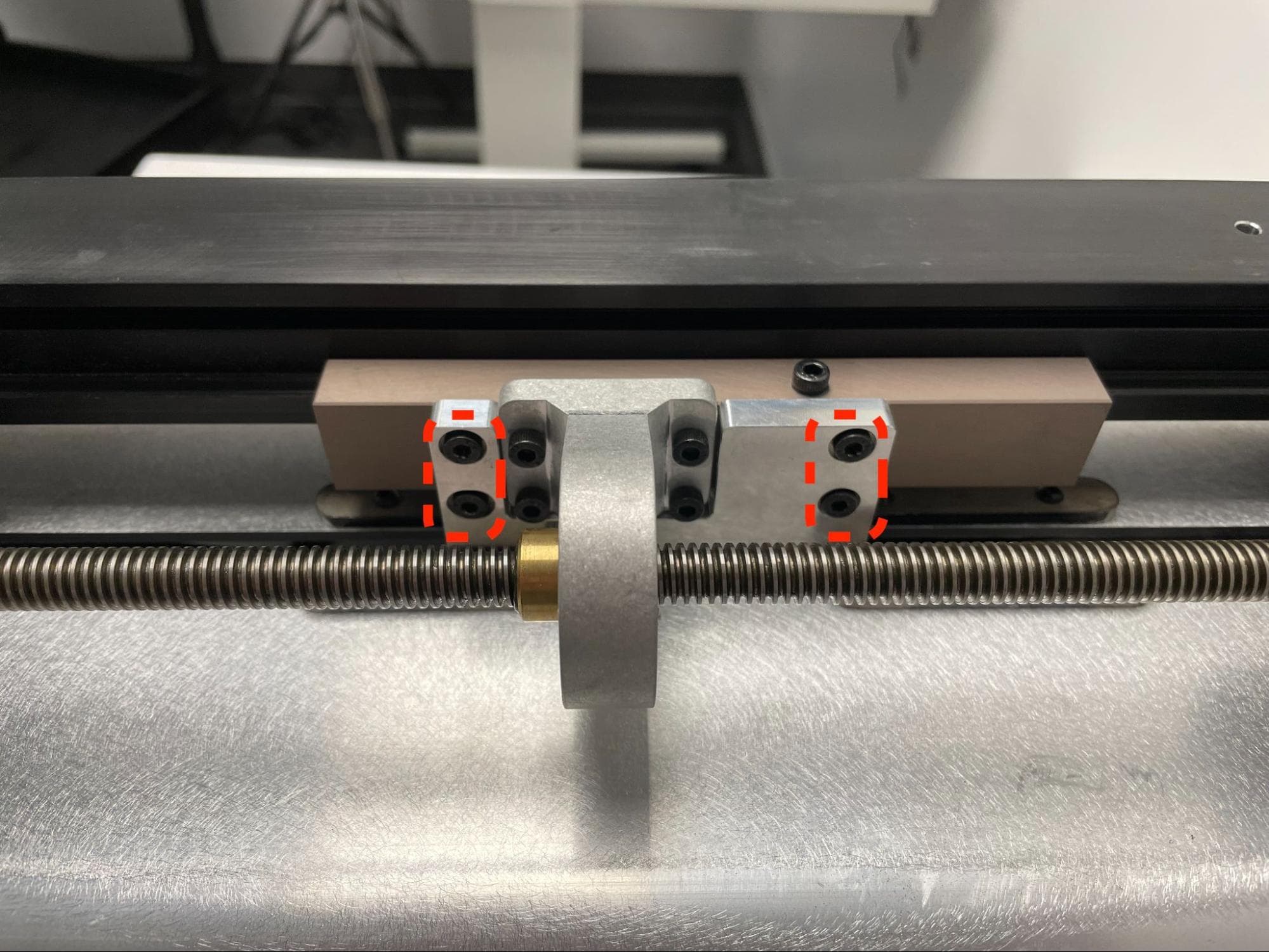
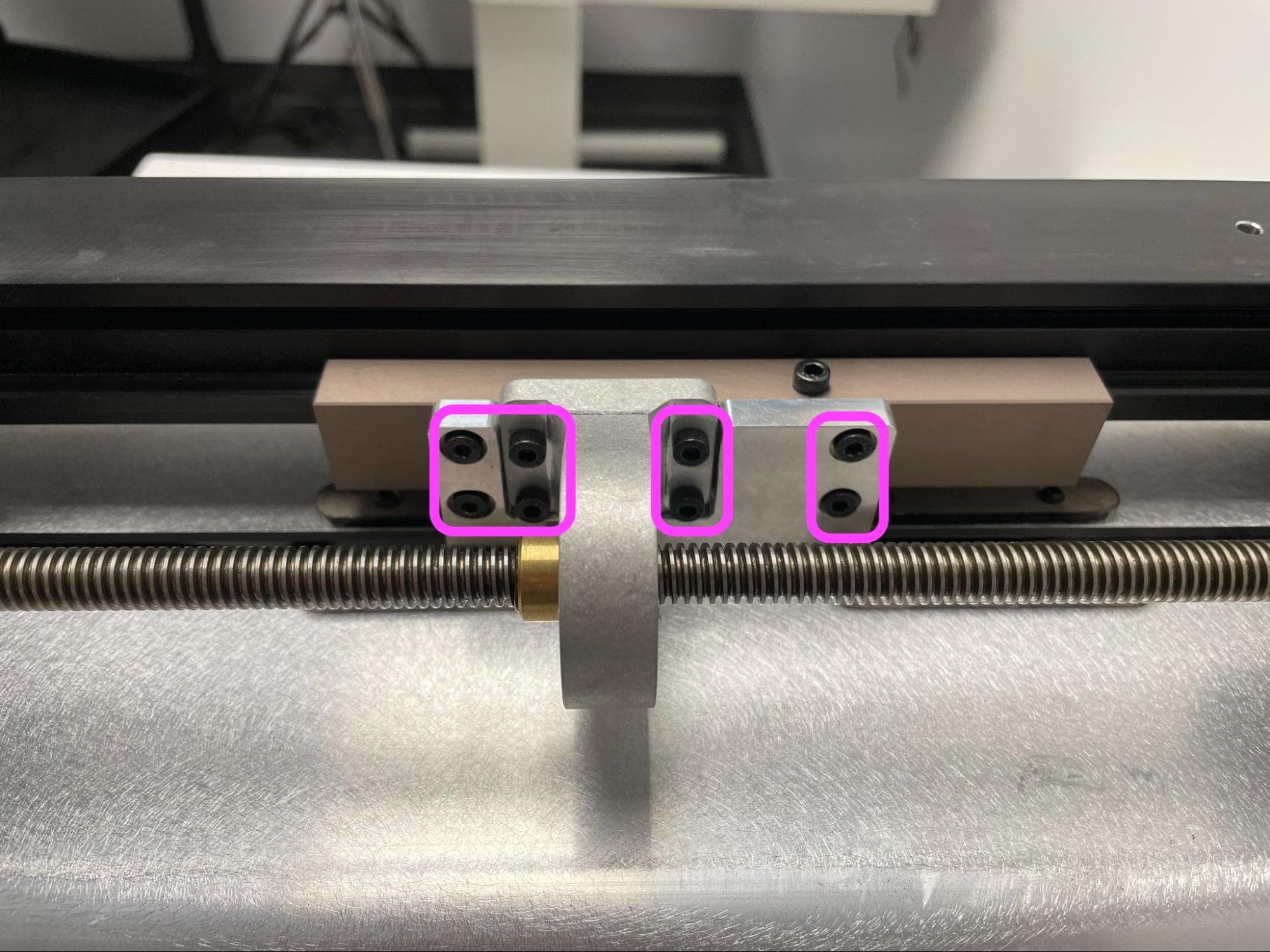
Use a 3.0 mm Allen key to remove only one of the four 10.0 mm M4 socket screws securing the lead nut mount to the Z-axis carriage. Clean and re-secure the screw:

  1. Using a non-abrasive lint-free wipe or swab and acetone, clean any existing threadlocker off the screw and corresponding internal threads.
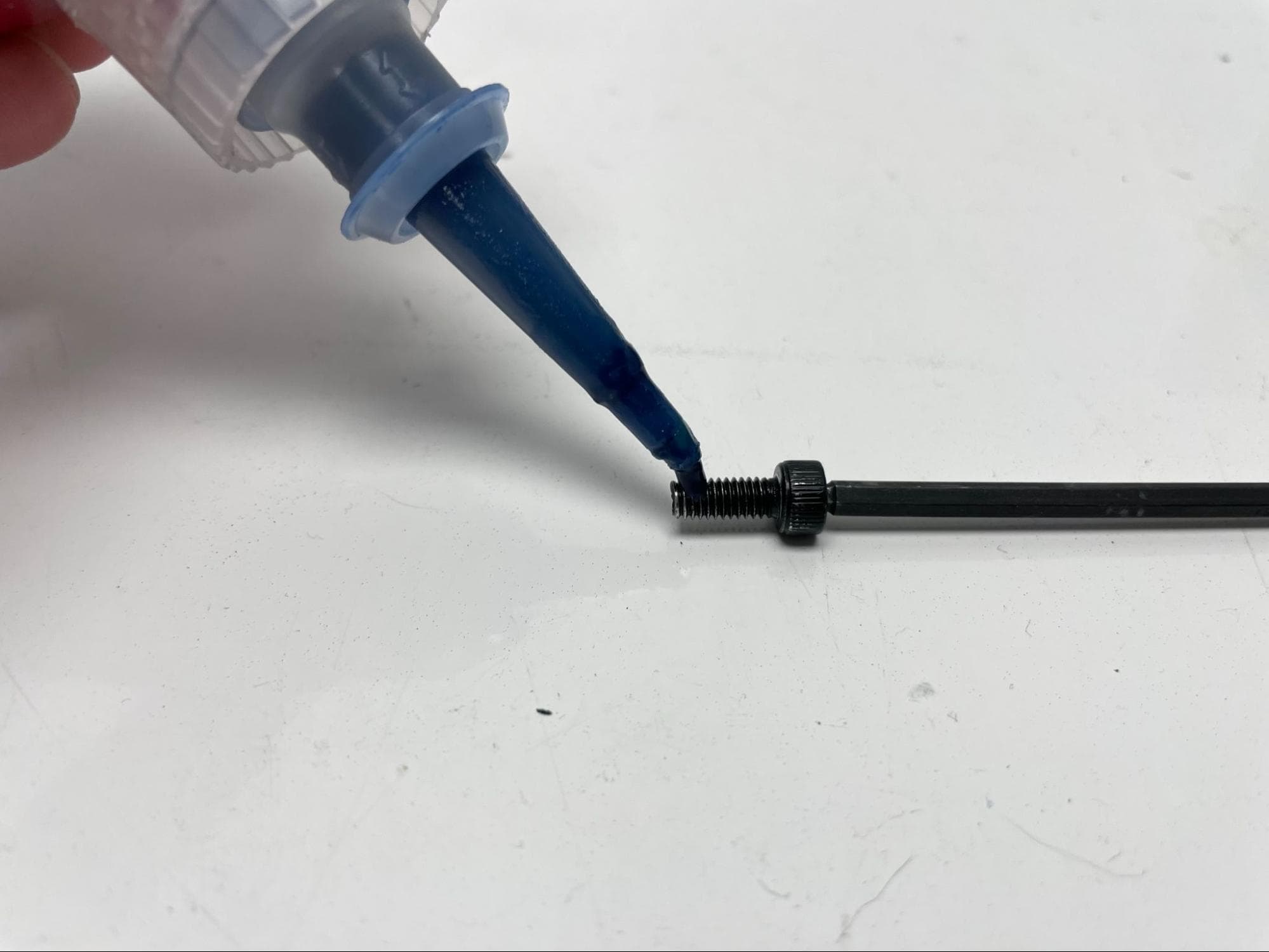
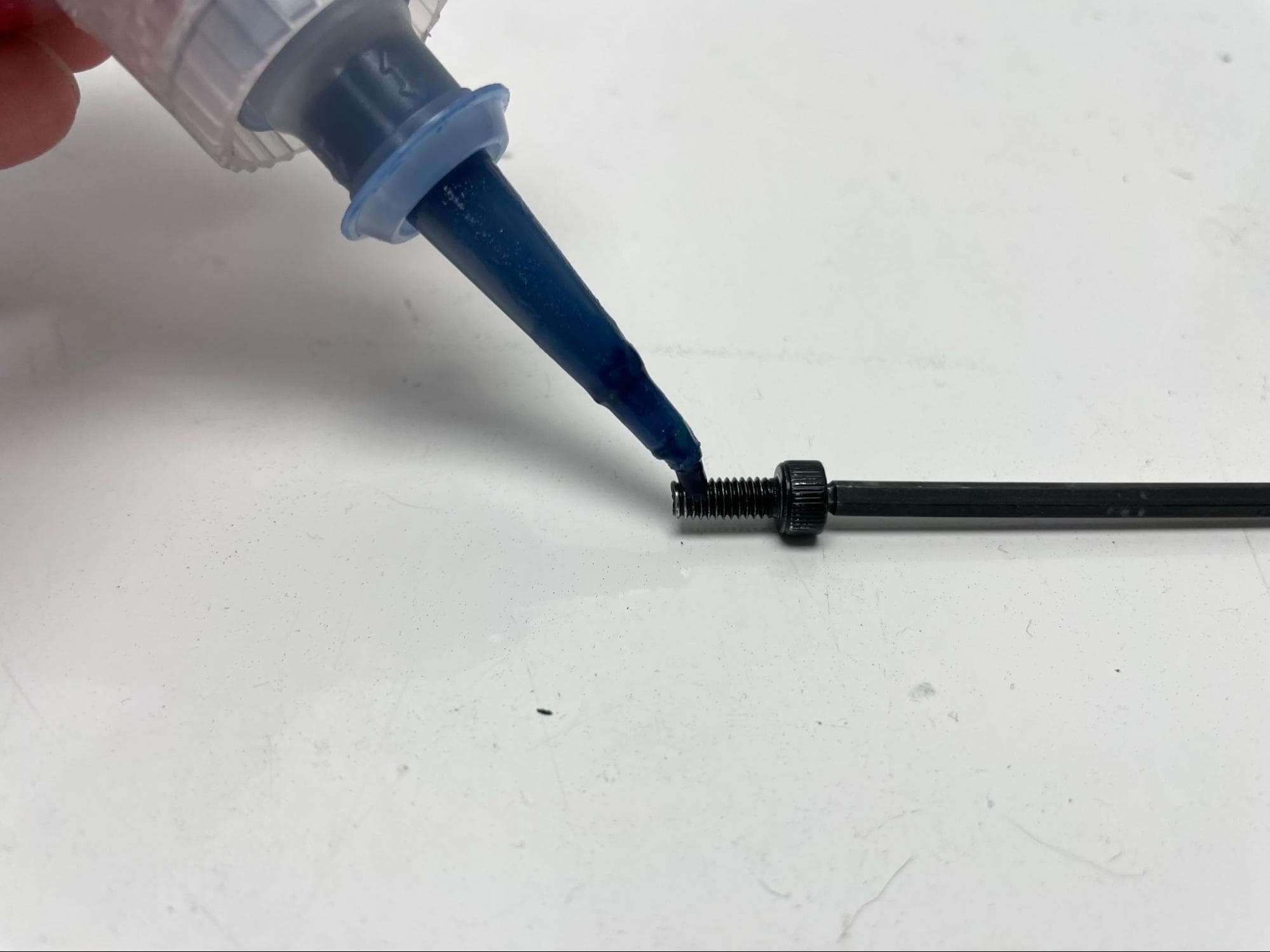
  2. Apply a small dab (roughly 2–3 mm in diameter) of Loctite 246 or other equivalent threadlocker to the tip of the thread shaft. Allow the drop to roll along the threads but not drip off.
  3. Promptly replace the socket screw into the lead screw mount. Using a torque driver and a flat-end 3.0 mm hex driver bit, tighten the screw to 2.2 N-m.
  4. Repeat for the other three screws, one at a time.

Step 5: Secure the piston arm screws

Check the carriage screws

Use a 3.0 mm Allen key to remove only one of the four 10.0 mm M4 socket screws securing the piston arm to the Z-axis carriage. Clean and re-secure the screw:

  1. Using a non-abrasive lint-free wipe or swab and acetone, clean any existing threadlocker off the screw and corresponding internal threads.
  2. Apply a small dab (roughly 2–3 mm in diameter) of Loctite 246 or other equivalent threadlocker to the tip of the thread shaft. Allow the drop to roll along the threads but not drip off.
  3. Promptly replace the socket screw into the lead screw mount. Using a torque driver and a flat-end 3.0 mm hex driver bit, tighten the screw to 2.2 N-m.
  4. Repeat for the other three screws, one at a time.

Step 6: Rotate the build chamber

Carefully turn the build chamber upside down and rest it on its top surface. Do not pick up the build chamber by its handle while the rear shell is removed.

Check the carriage screws

Step 7: Secure the first bellows

Check the carriage screws

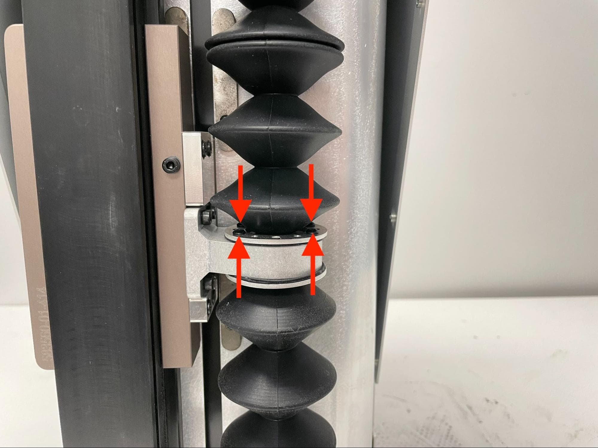
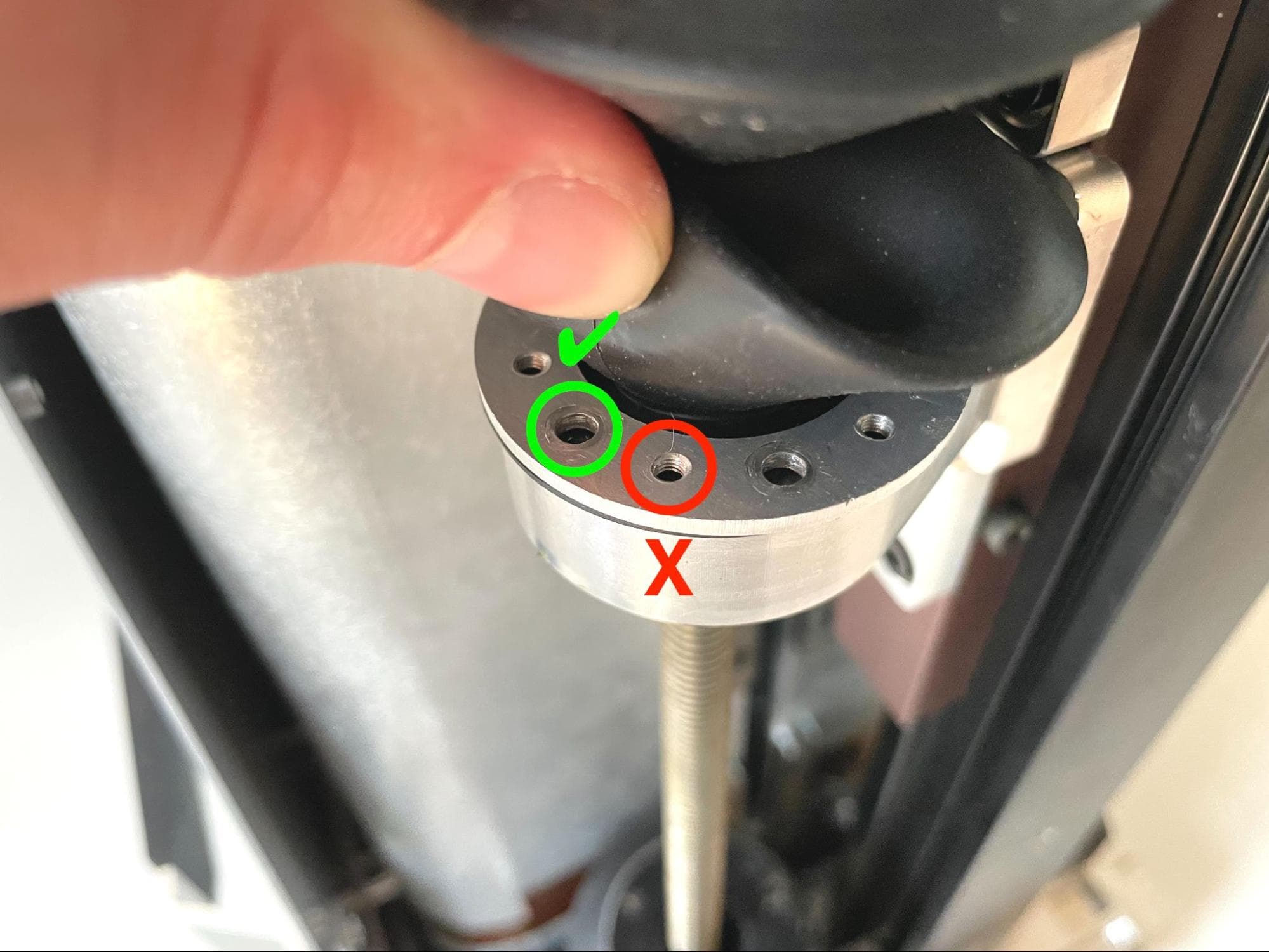
Expand the top-most bellows, bringing the metal flange down to the lead nut mount. Align the unthreaded screw holes in the metal bellows flange with the holes in the lip of the rubber bellows, then thread one 6.0 mm black M3 button head screw through each of the four screw holes in the flange and rubber lip.

Using a 2.0 mm Allen key, tighten the screws until finger-tight.

Step 8: Rotate the build chamber

Carefully turn the build chamber right-side up. Do not pick up the build chamber by its handle while the rear shell is removed.

Step 9: Secure the second bellows

Repeat step 7 for the second bellows.

Reinstalling the rear enclosure shell

Overview: After securing the carriage screws, reinstall the rear enclosure shell.

Step 1: Mount the rear enclosure shell

Mount the rear enclosure shell on the build chamber frame, aligning the 15 screw holes around the shell with the corresponding screw holes in the build chamber.

Step 2: Secure the rear enclosure shell

Replace the rear enclosure shell

Apply a small dab of Loctite 246 or other equivalent threadlocker to each of the 6.0 chrome M3 button head screws that secured the rear enclosure shell to the build chamber. Thread one screw into each of the 15 screw holes, then use a 2.0 mm hex driver to tighten until snug.

Step 3: Secure the build chamber handle

Replace the rear enclosure shell

Thread one 10.0 mm chrome M4 button head screw into each of the eight screw holes at the ends of the build chamber handle. Using a 2.5 mm hex driver, tighten until snug.

Checking and securing the heater plate spacer screws

Overview: Apply threadlocker to the screws securing the piston heater plate spacers to the piston base.

Step 1: Reposition the build chamber piston

Reinsert the build chamber into your printer or Fuse Sift. Use the machine to lower the piston top to its lowest position. You can use the control panel on the Fuse Sift or tap Maintenance > Move Motors on the printer touchscreen to control the piston top position, as you did when the print bed was still installed.

Once the piston is in position, remove the build chamber from the printer or Fuse Sift.

Position the piston (2 of 3)

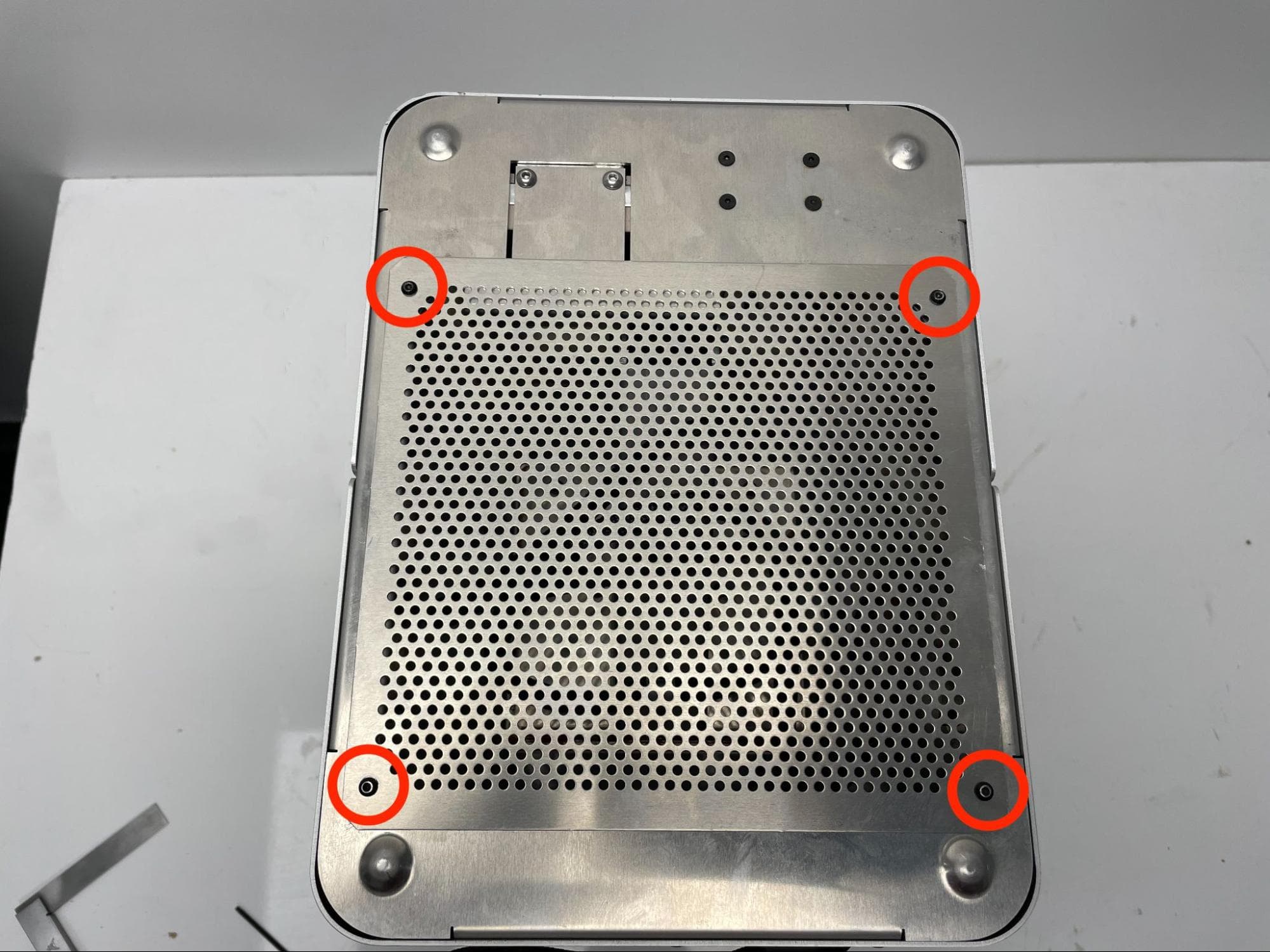
Step 2: Remove the bottom enclosure plate

Check the heater plate spacer screws

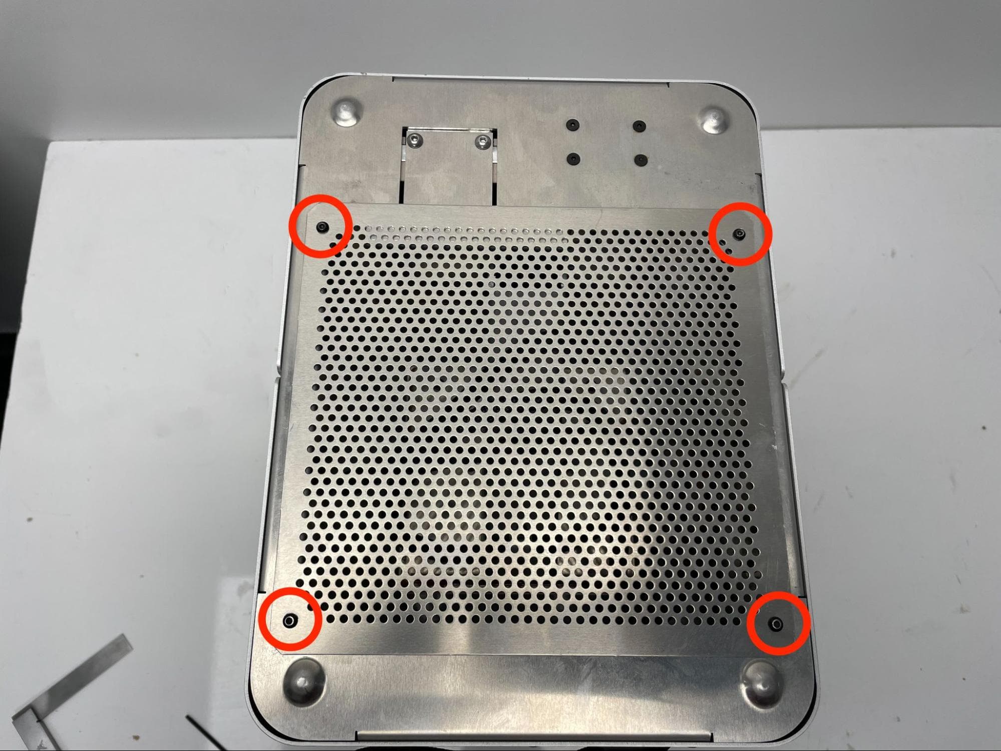
Turn the build chamber upside-down and place it onto a flat, clean work surface with the connector facing you.

Using a 2.0 mm hex driver, loosen and remove the four 5.0 mm M3 button head screws securing the bottom enclosure plate to the build chamber. Set the screws and enclosure plate aside.

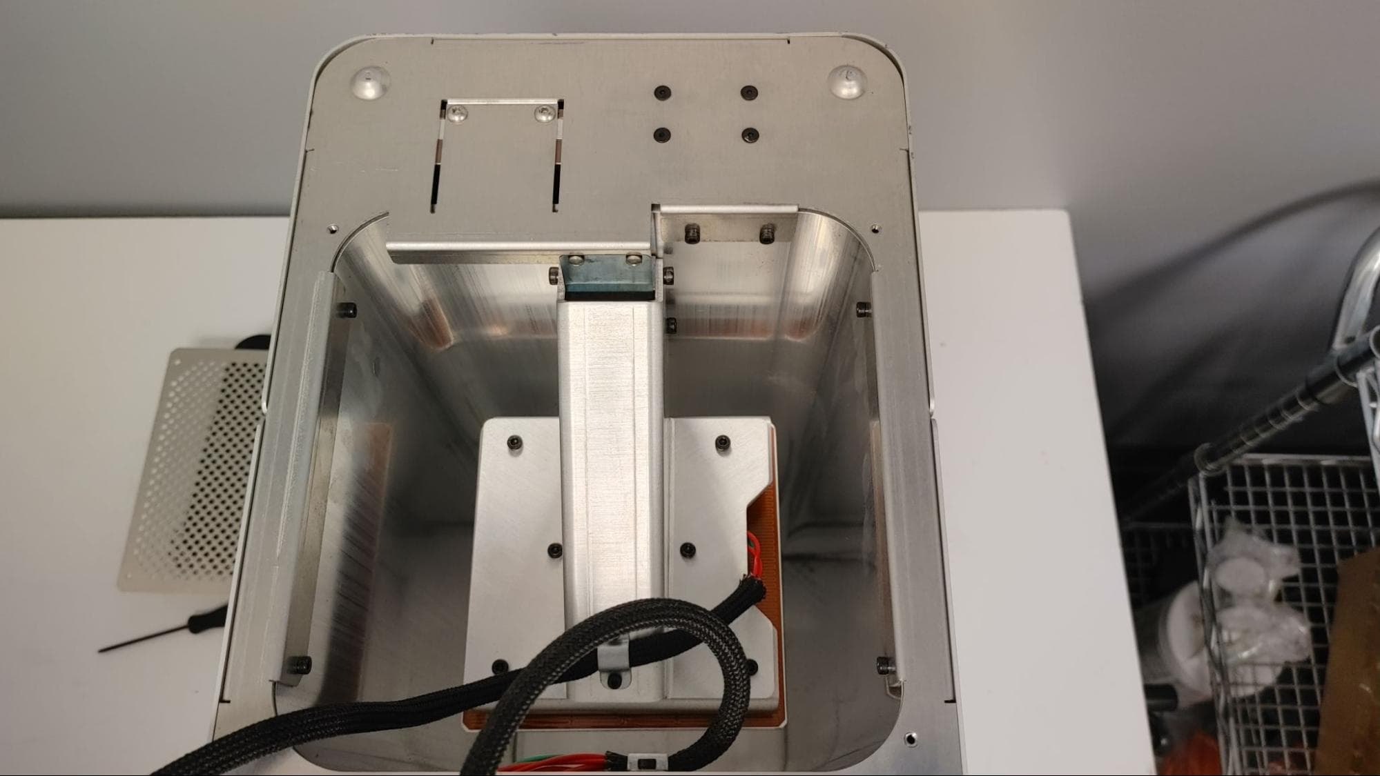
Step 3: Move the build chamber cable harness

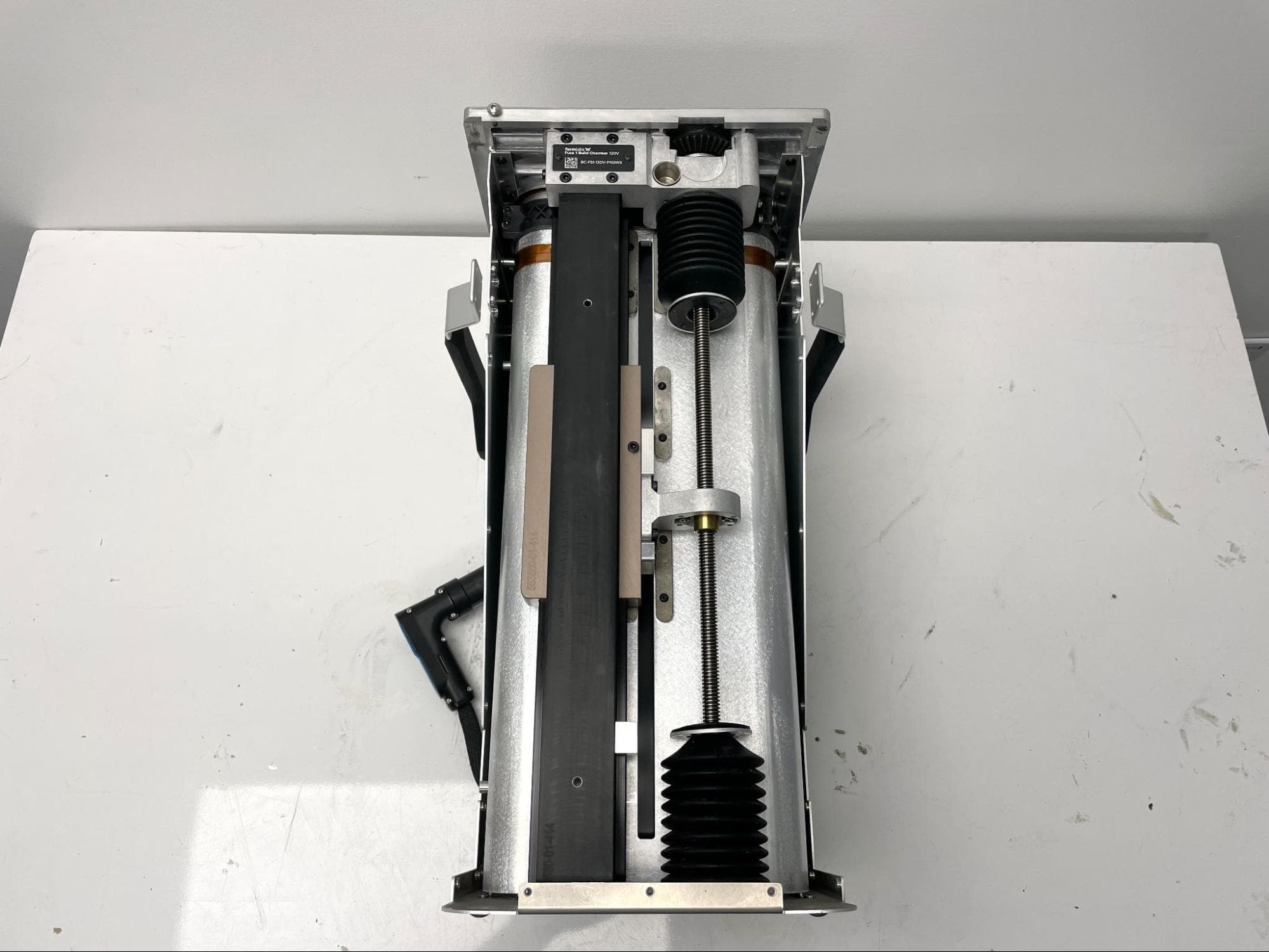
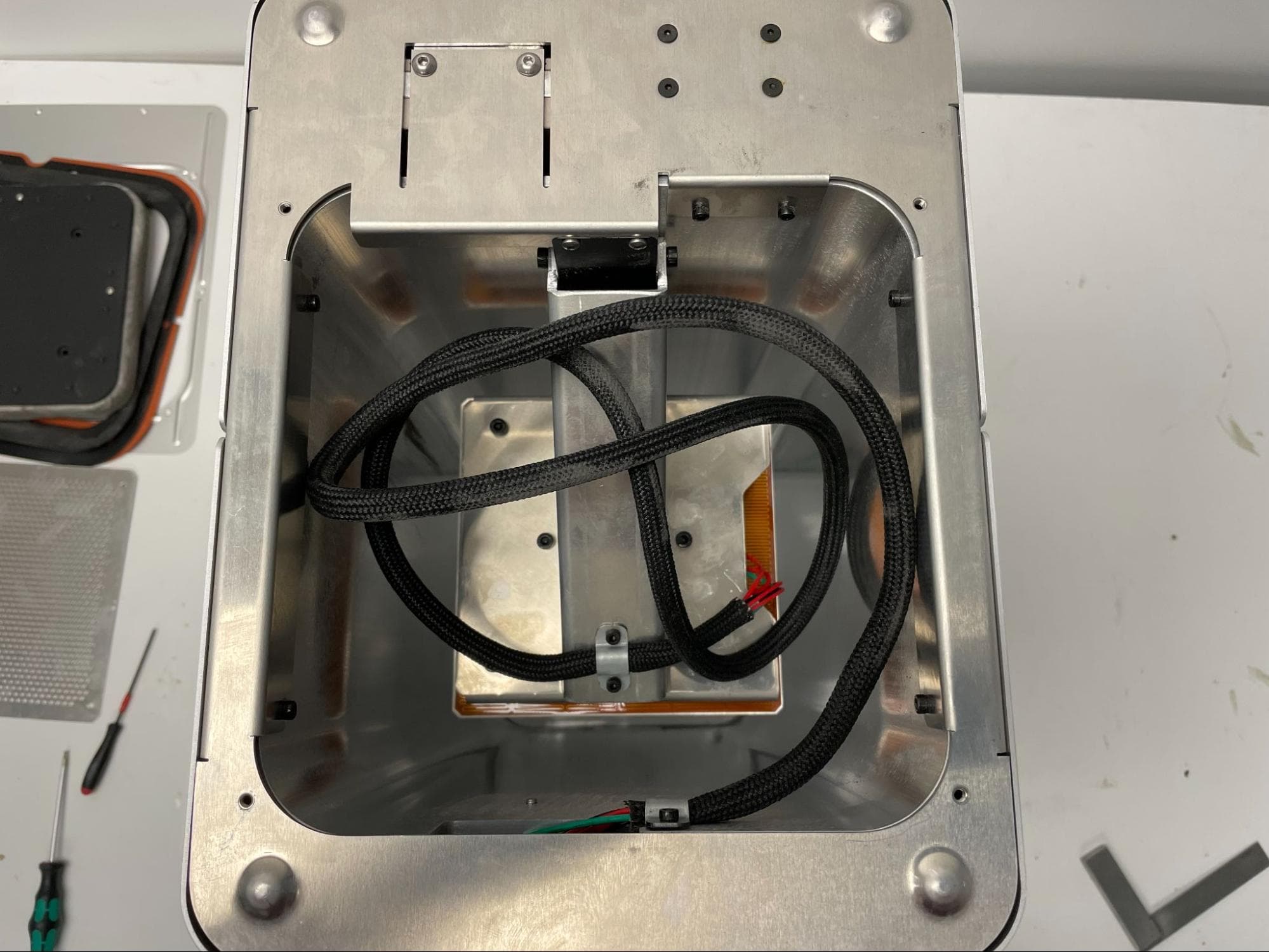
Carefully move the cable harness out of the build chamber to gain unobstructed access to the underside of the piston assembly.

Check the heater plate spacer screws

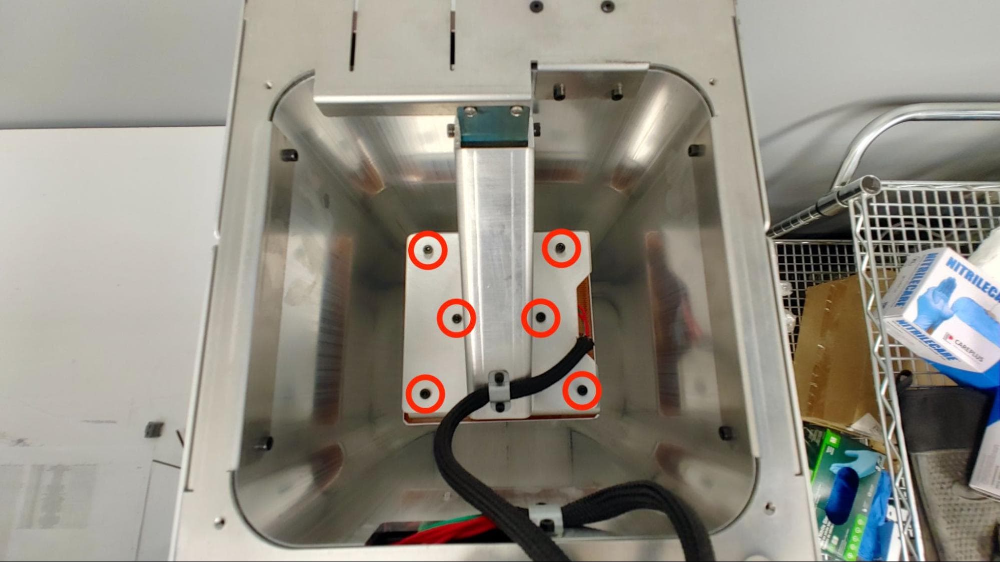
Step 4: Secure the piston heater plate spacer screws

Use a 3.0 mm Allen key to remove only one of the six 10.0 mm M4 socket screws securing the piston heater plate spacers to the piston base. Clean and re-secure the screw:

  1. Using a non-abrasive lint-free wipe or swab and acetone, clean any existing threadlocker off the screw and corresponding internal threads.
  2. Apply a small dab (roughly 2–3 mm in diameter) of Loctite 246 or other equivalent threadlocker to the tip of the thread shaft. Allow the drop to roll along the threads but not drip off.
  3. Promptly replace the socket screw into the heater plate. Using a torque driver and a flat-end 3.0 mm hex driver bit, tighten the screw to 2.2 N-m.
  4. Repeat for the other five screws, one at a time.
Check the heater plate spacer screws

Checking and securing the piston arm bracket screws

Overview: Apply threadlocker to the screws securing the piston arm to the linear Z-axis carriage.

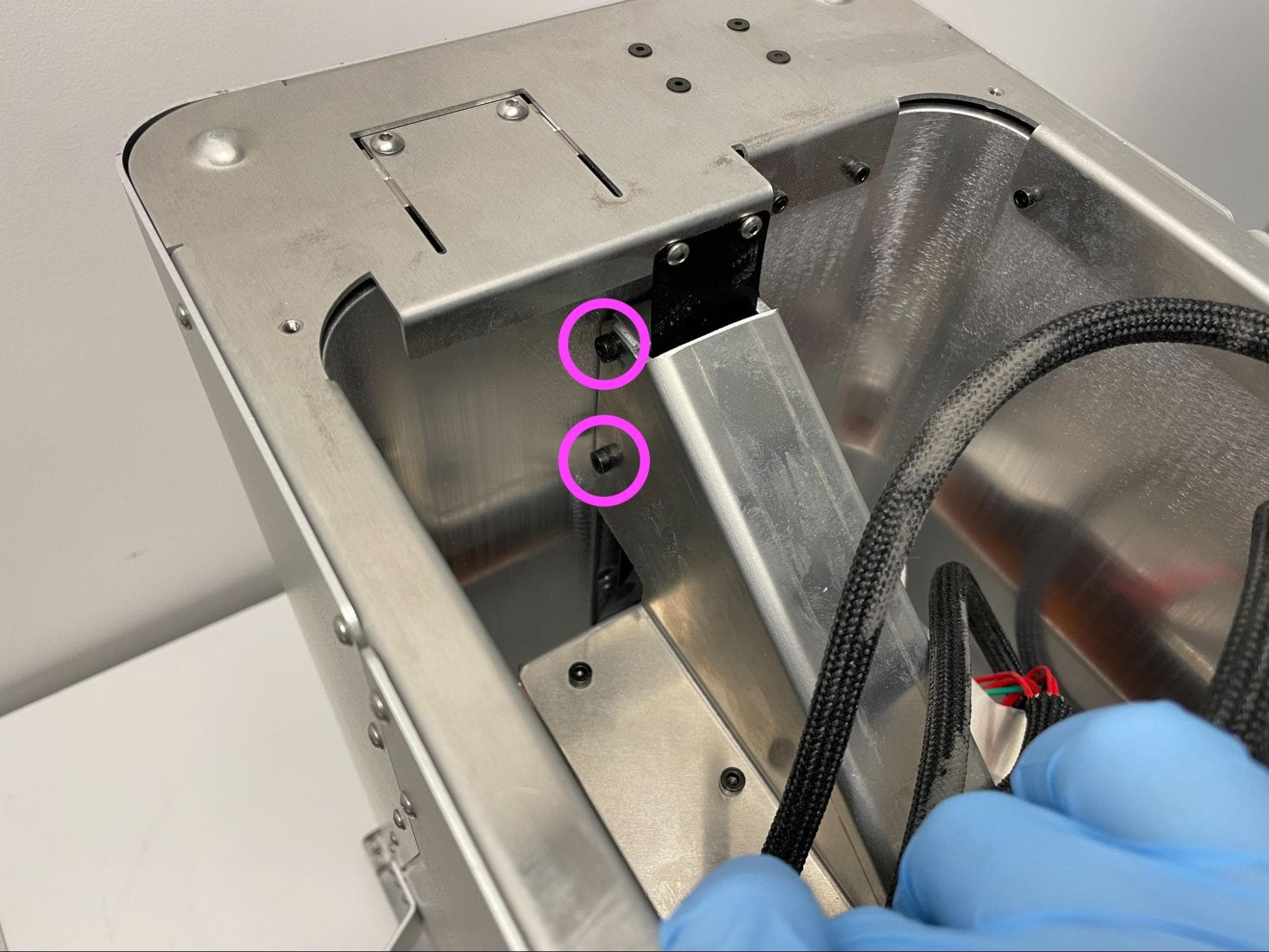
Step 1: Locate the piston arm screws

Check the piston arm bracket screws

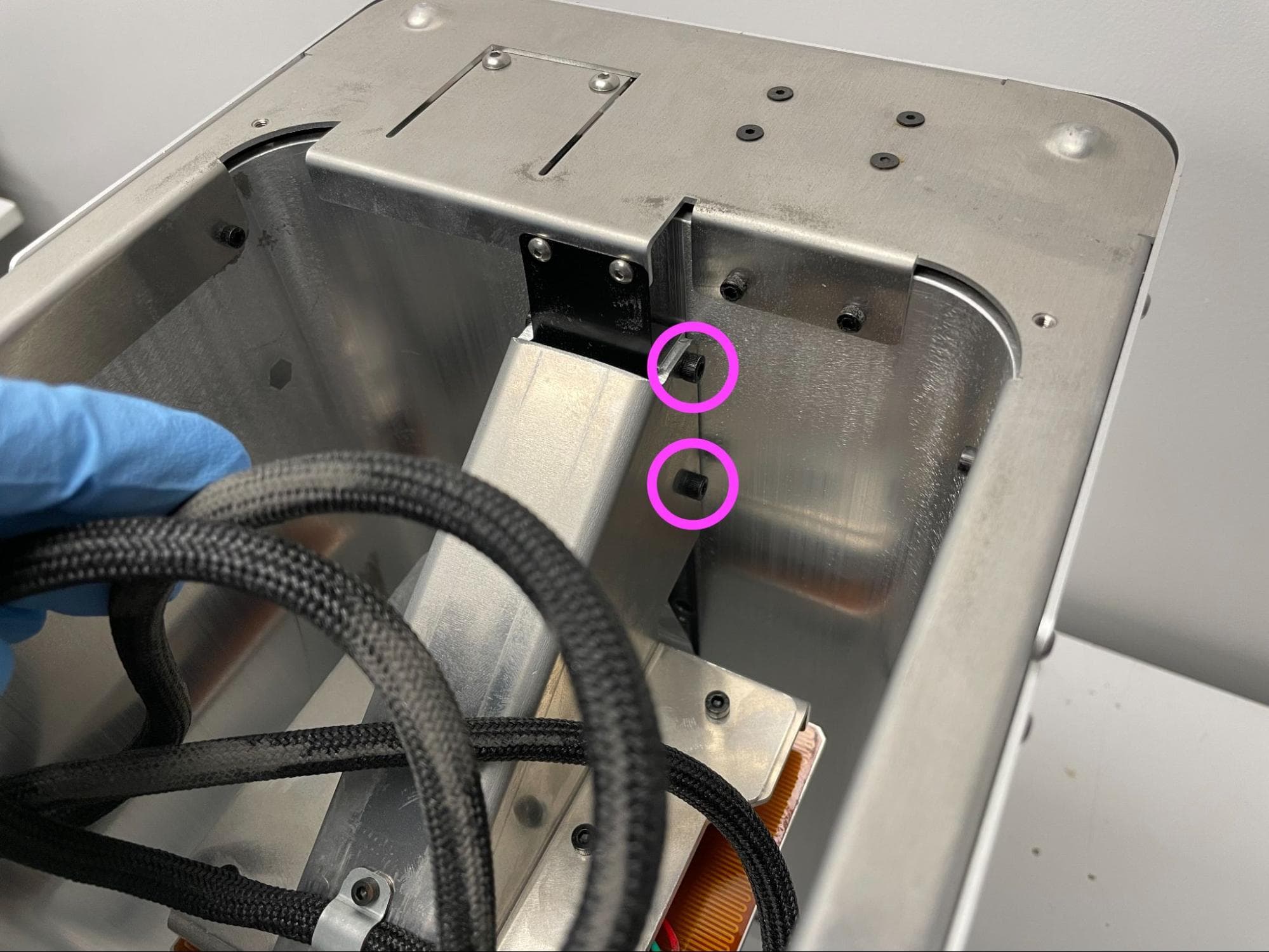
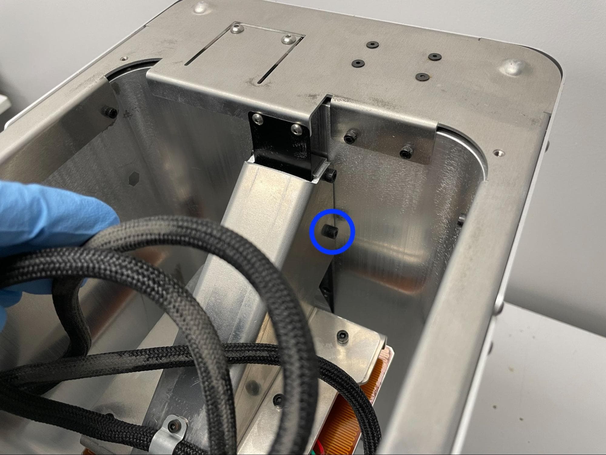
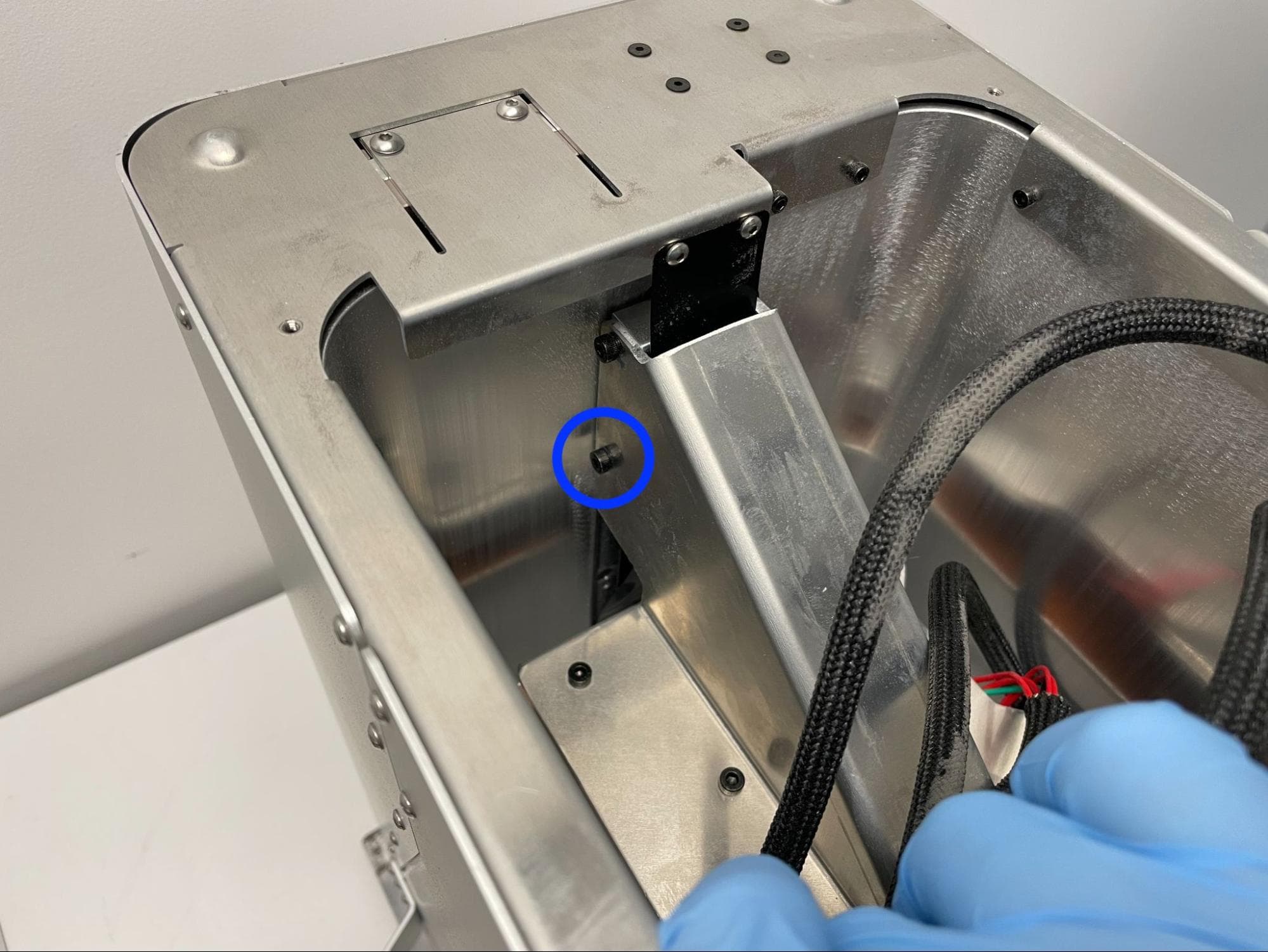
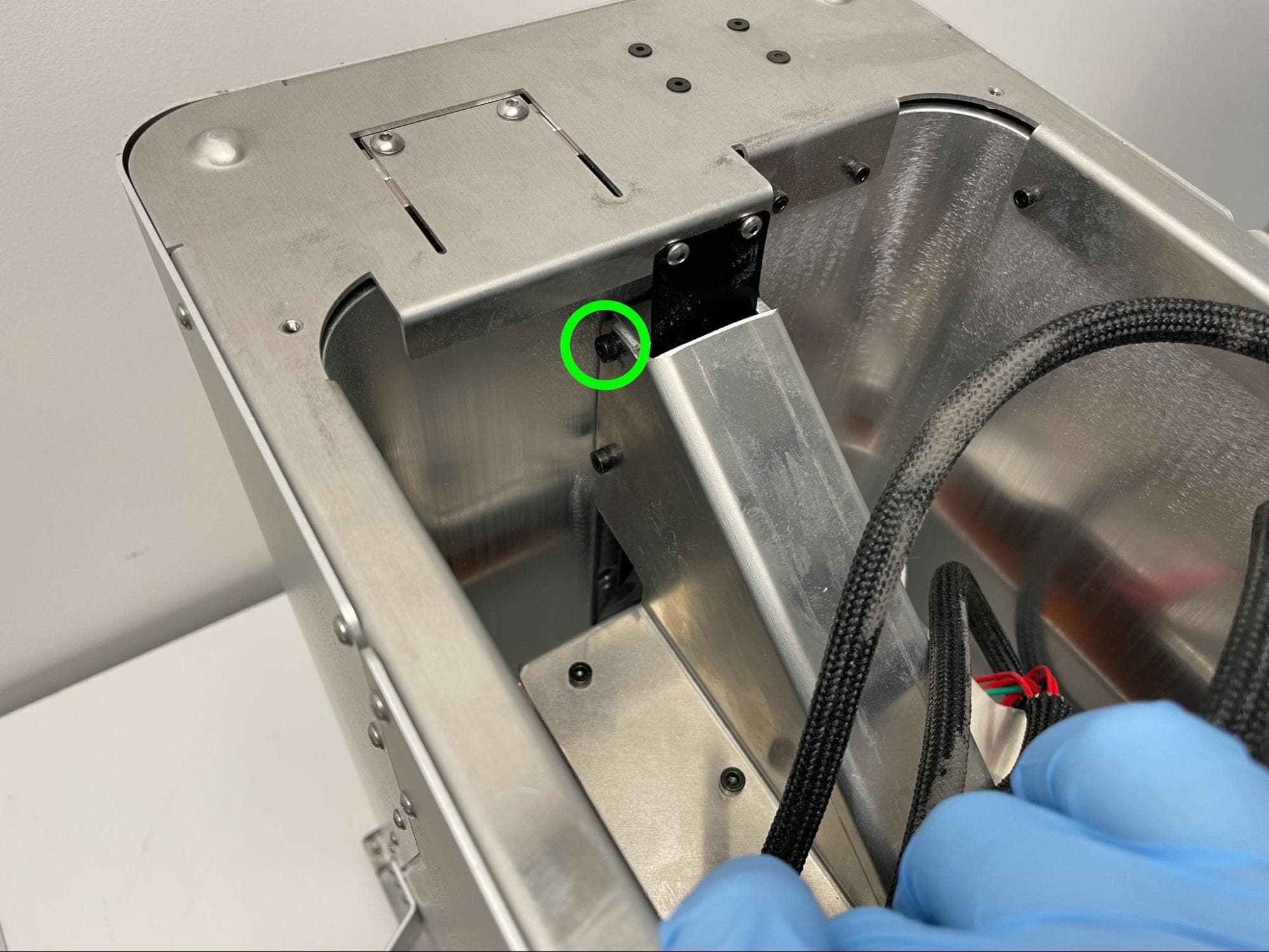
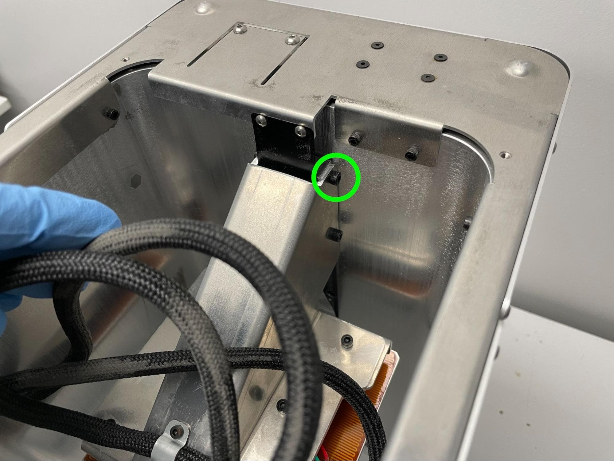
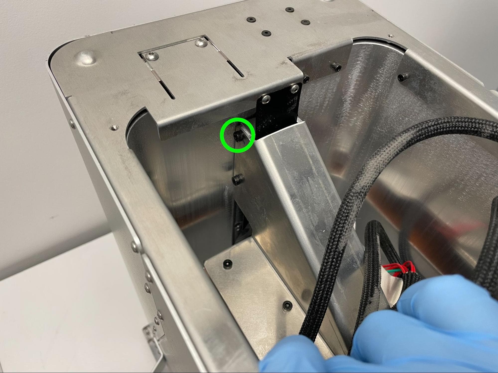
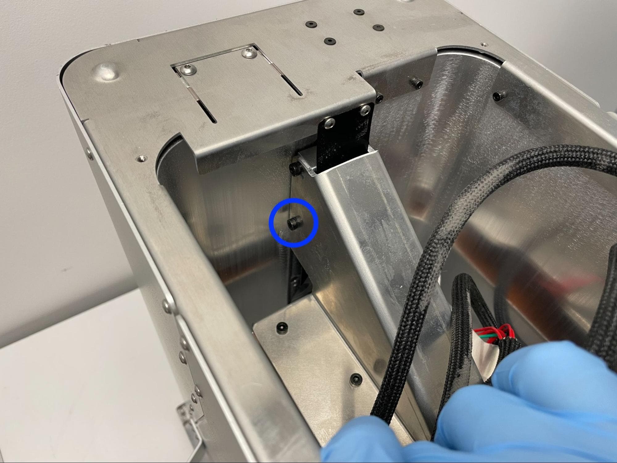
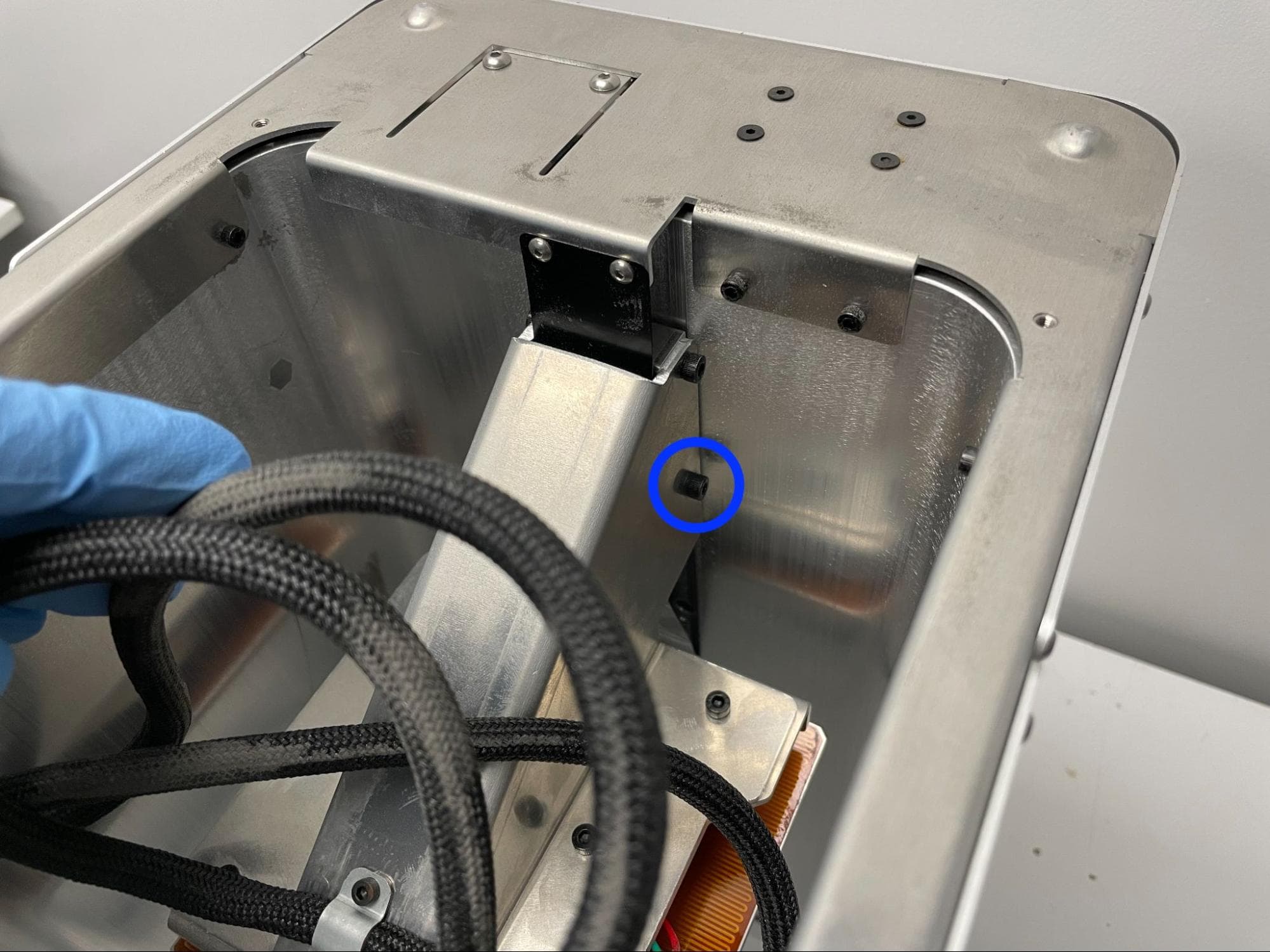
Locate the four 10.0 mm black M4 socket screws securing the piston arm to the linear Z-axis carriage. You may need to move the inner build chamber wire harness out of the way in order to locate the screws.

Step 2: Begin securing the piston arm screws

Check the piston arm bracket screws

Use a 3.0 mm Allen key to remove only one of the four 10.0 mm M4 socket screws securing the piston arm to the linear Z-axis carriage. Clean and re-secure the screw:

  1. Using a non-abrasive lint-free wipe or swab and acetone, clean any existing threadlocker off the screw and corresponding internal threads.
  2. Apply a small dab (roughly 2–3 mm in diameter) of Loctite 246 or other equivalent threadlocker to the tip of the thread shaft. Allow the drop to roll along the threads but not drip off.
  3. Promptly thread the socket screw into the piston arm but do not fully torque the screw at this time.
  4. Repeat for the other three screws, one at a time.

Step 3: Check that the piston arm is perpendicular to the inner build chamber wall

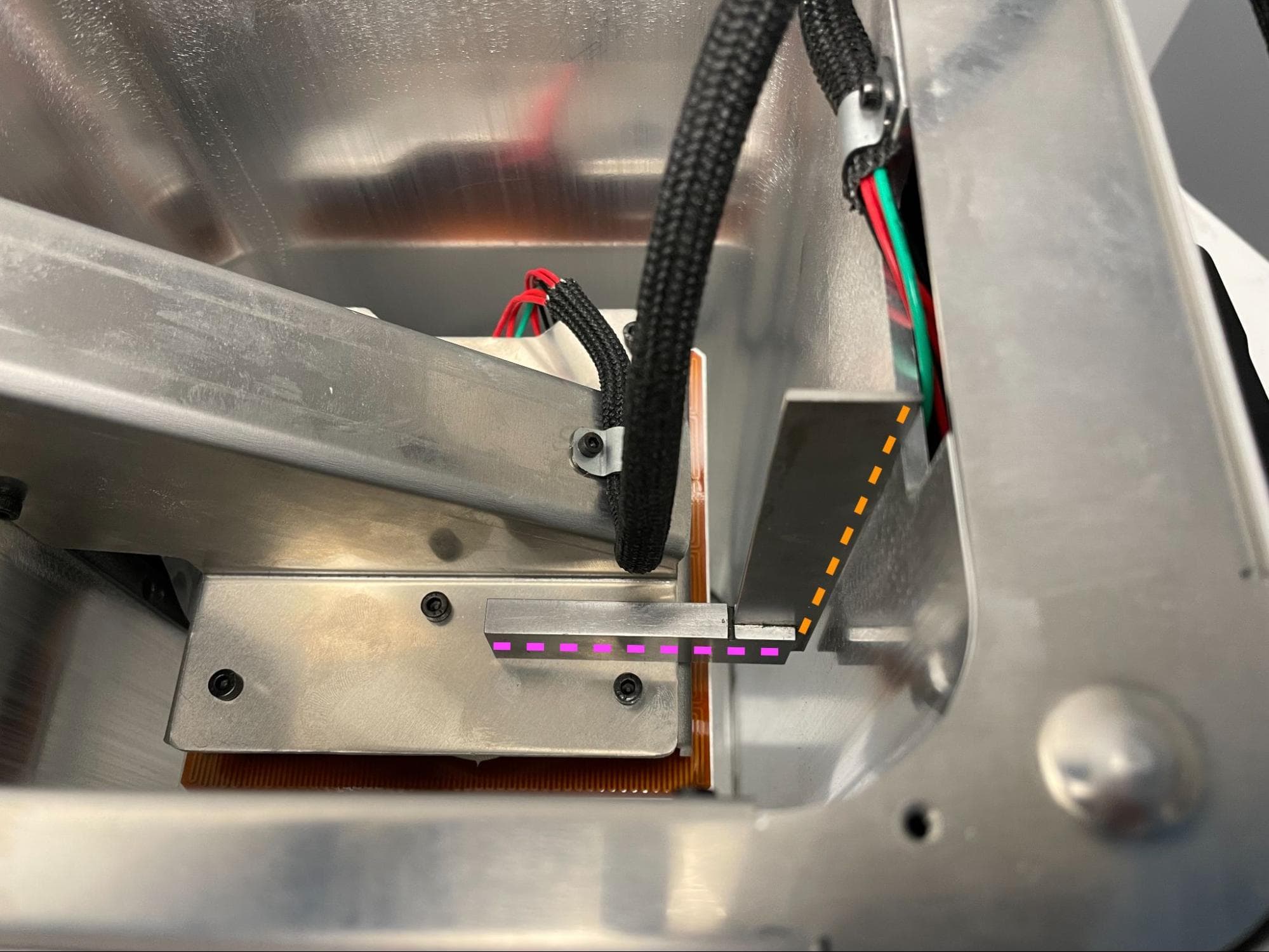
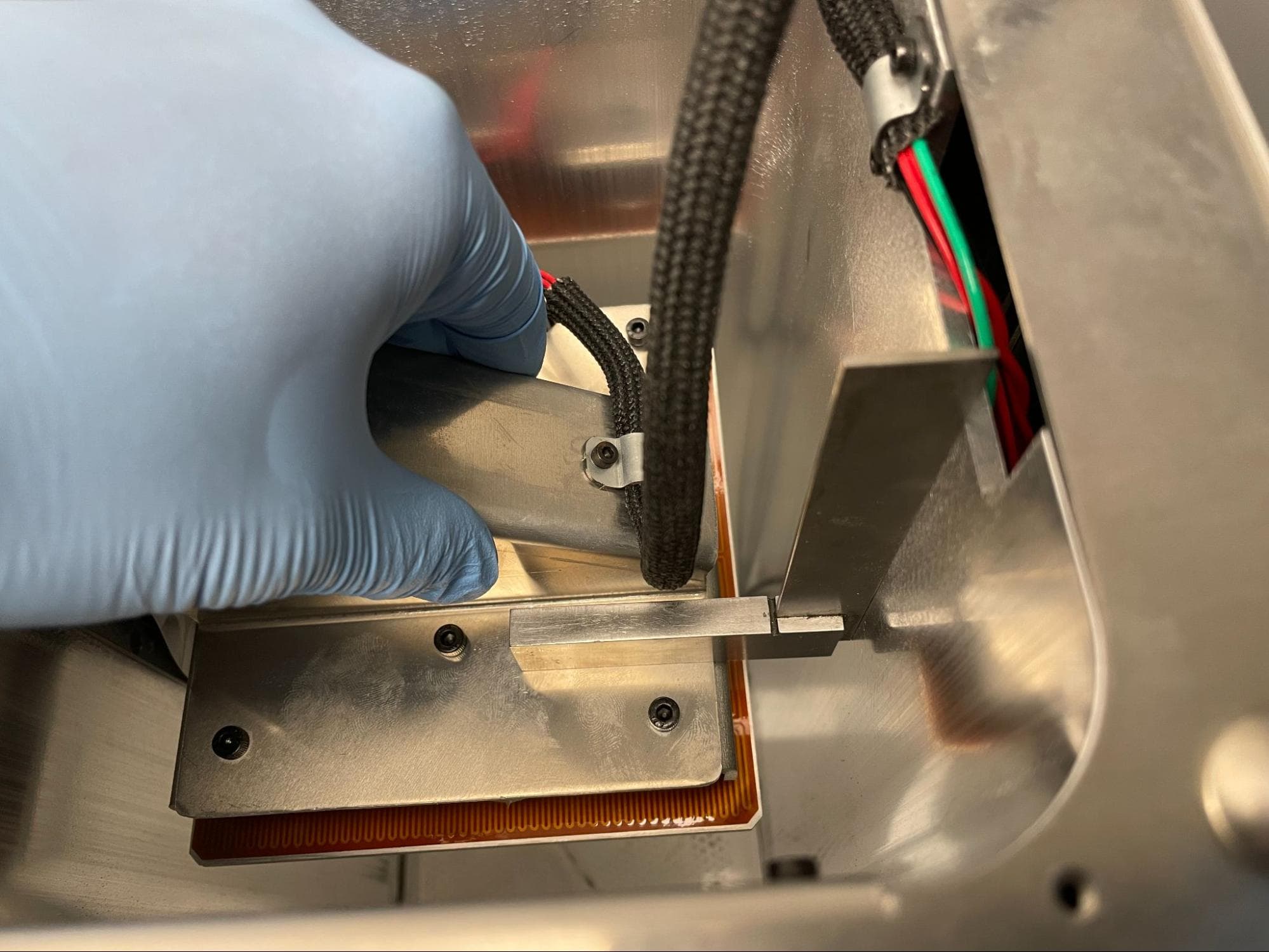
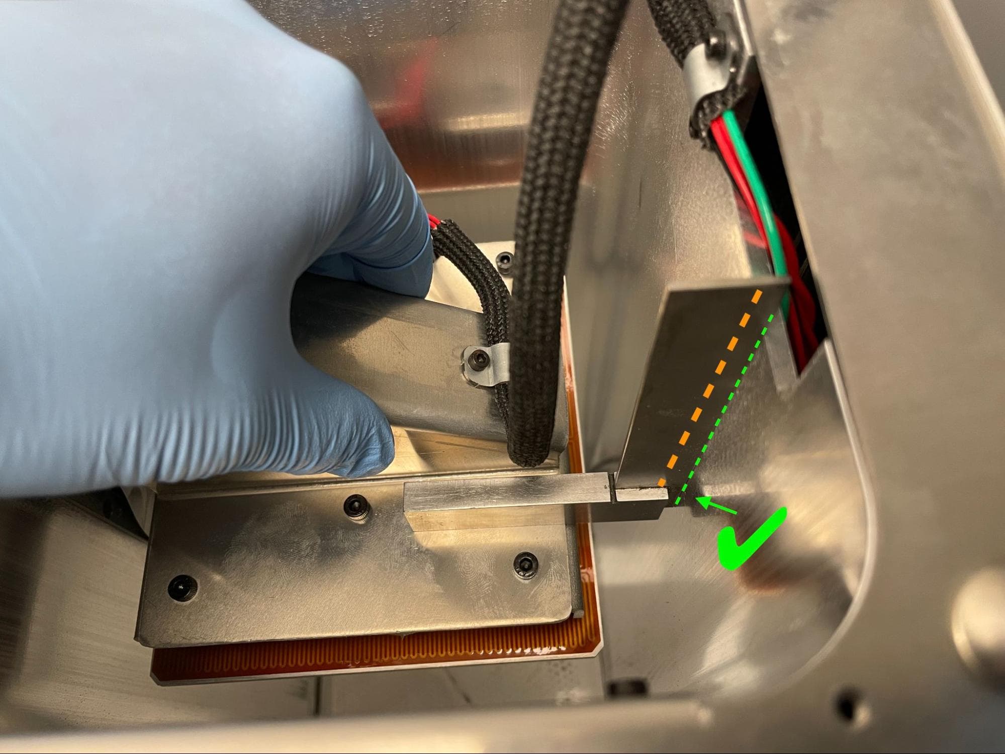
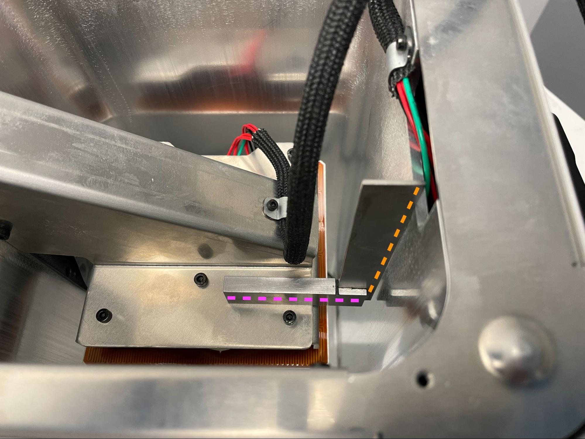
Place a machinist square block onto the left-hand underside of the piston arm. Move the machinist square blade so it is touching the adjacent forward face of the inner build chamber wall.

Check the piston arm bracket screws

Step 4: Adjust the piston arm

Check the piston arm bracket screws

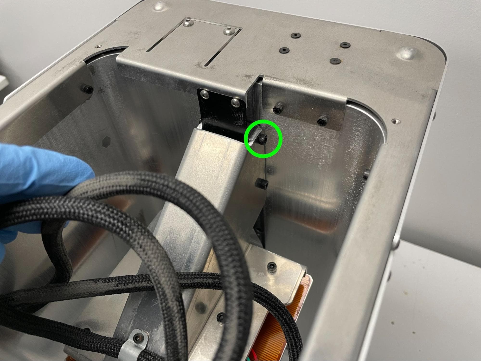
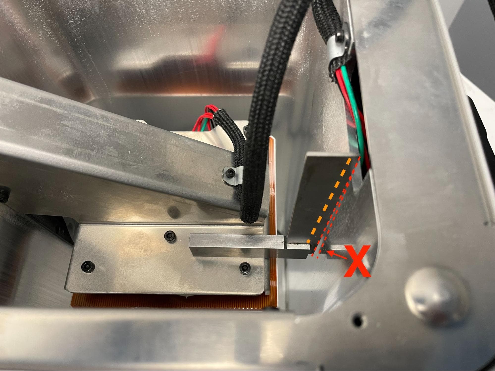
Adjust the piston arm so the outer edge of the blade is flush with the inner wall. Keep the blade to the left of the exposed screw shank.

Notice:

Exercise caution if using a metal square. Scratching or gouging the build chamber inner wall may damage the print bed felt seal, causing leaks.

Step 5: Fully secure the piston arm screws

Check the piston arm bracket screws

Once the piston arm base is perpendicular to the inner wall, use a torque driver and a flat-end 3.0 mm hex driver bit to tighten the topmost right-hand piston arm screw, opposite the square, to 2.2 N-m.

Repeat for the other three screws, one at a time, checking for perpendicularity after tightening each one.

Step 6: Route the build chamber wire harness

Tuck the wire harness back into the build chamber in a figure-8 pattern. Ensure that the harness does not extend past the piston heater plate.

Check the piston arm bracket screws

Reassembling the build chamber

Overview: After securing all of the build chamber screws, reinstall the bottom enclosure plate and print bed.

Step 1: Mount and secure the bottom enclosure plate

Place the bottom enclosure plate onto the bottom of the build chamber. Align the four screw holes in the plate with the corresponding holes in the build chamber.

Thread one 5.0 mm M3 button head screw into each of the four screw holes, then use a 2.0 mm hex driver to tighten until snug.

Position the piston (3 of 3)

Step 2: Reposition the build chamber piston

Reinsert the build chamber into your printer or Fuse Sift. Use the machine to raise the piston top to its highest position. You can use the control panel on the Fuse Sift or tap Maintenance > Move Motors on the printer touchscreen to control the piston top position, as you did when the print bed was still installed.

Avoid spilling any powder into the build chamber with the print bed removed. Once the piston is in position, remove the build chamber from the printer or Fuse Sift.

Position the piston (3 of 3)

Step 3: Clean the piston top

Clean off any powder that may have been deposited onto the piston top. Wet a non-abrasive lint-free wipe with ethanol and wipe down the piston top.

Step 4: Inspect the print bed

Replace the print bed

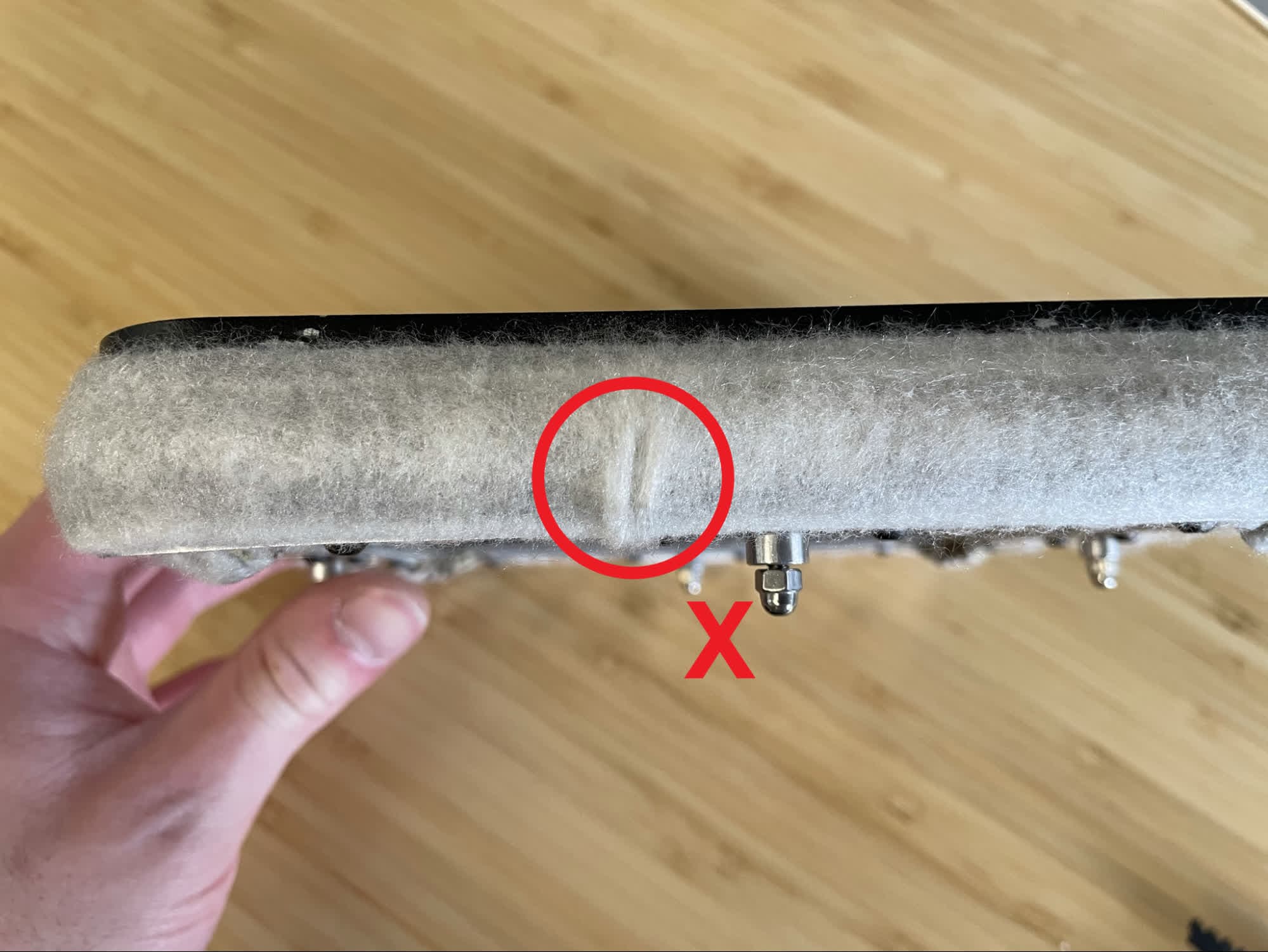
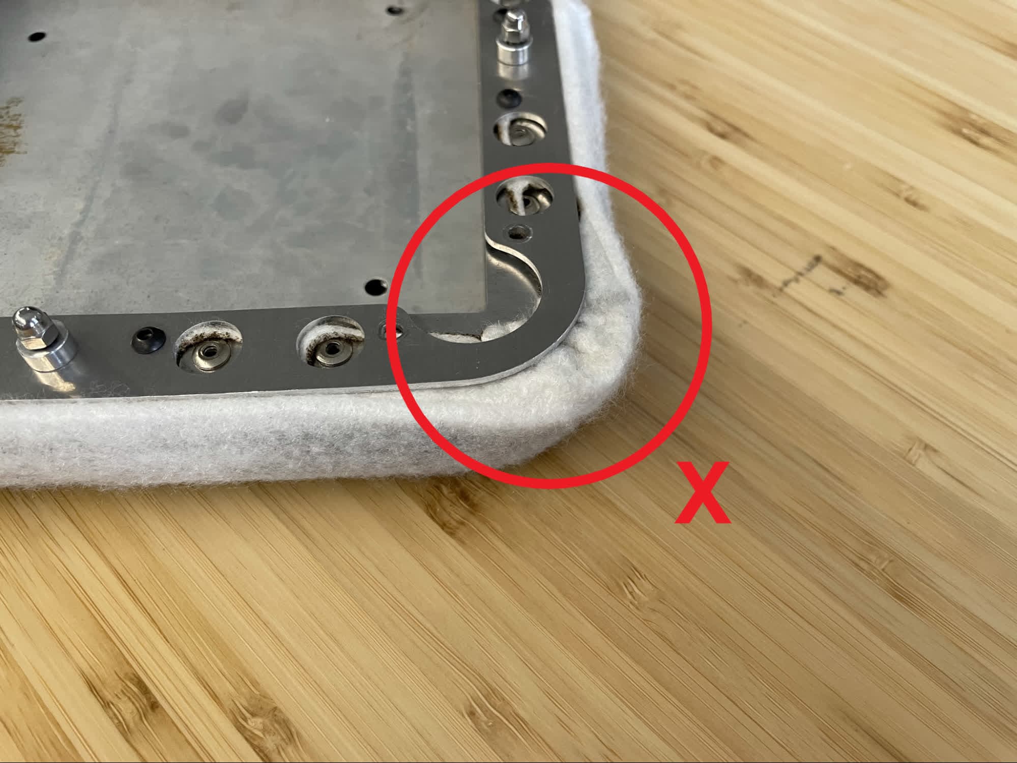
Inspect the felt seal around the edge of the print bed for any cuts or tears. Check that it is properly secured to the rest of the print bed assembly. Do not use the original print bed if the felt seal is damaged or detached from the assembly.

Step 5: Mount the print bed

Replace the print bed

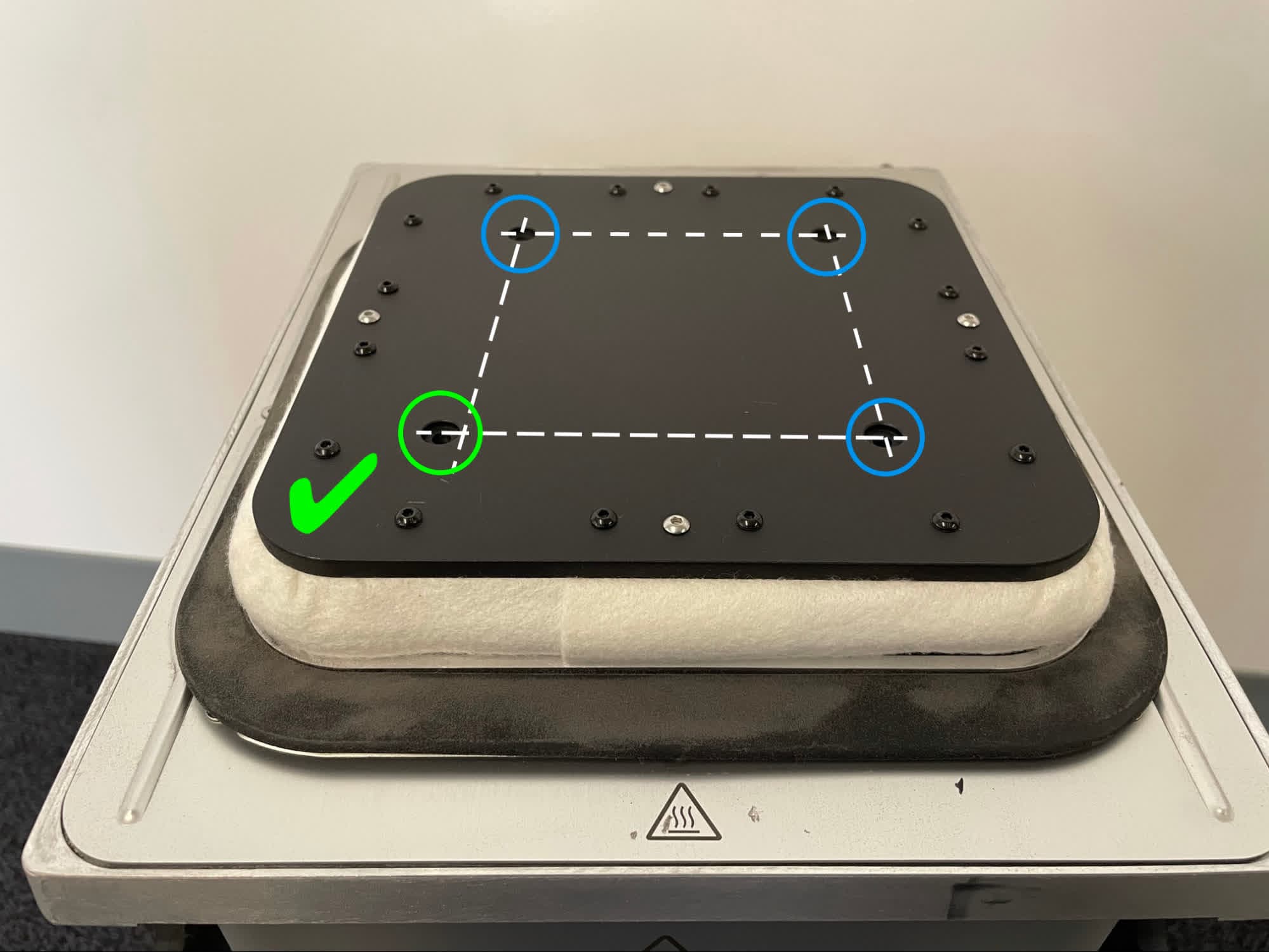
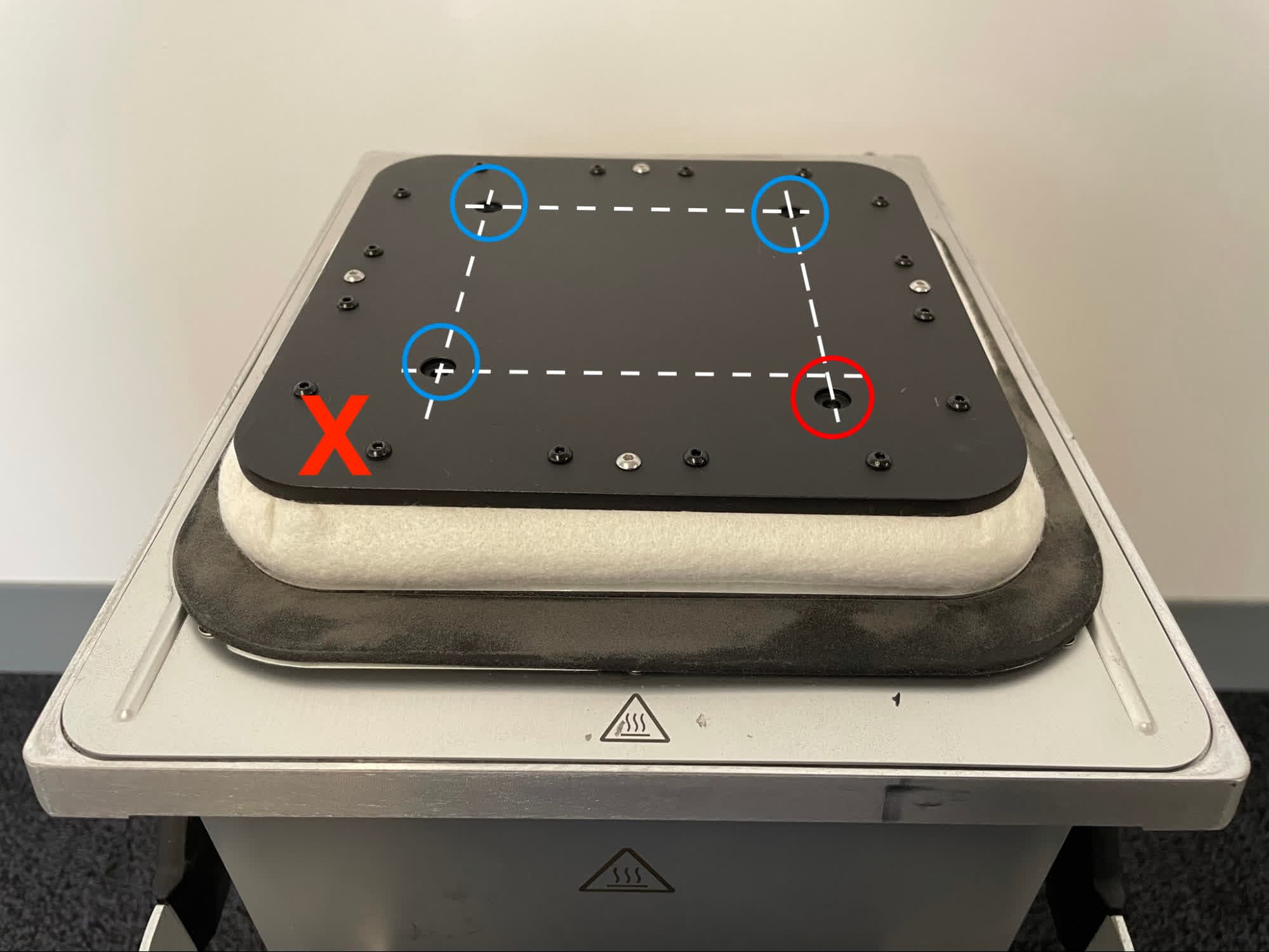
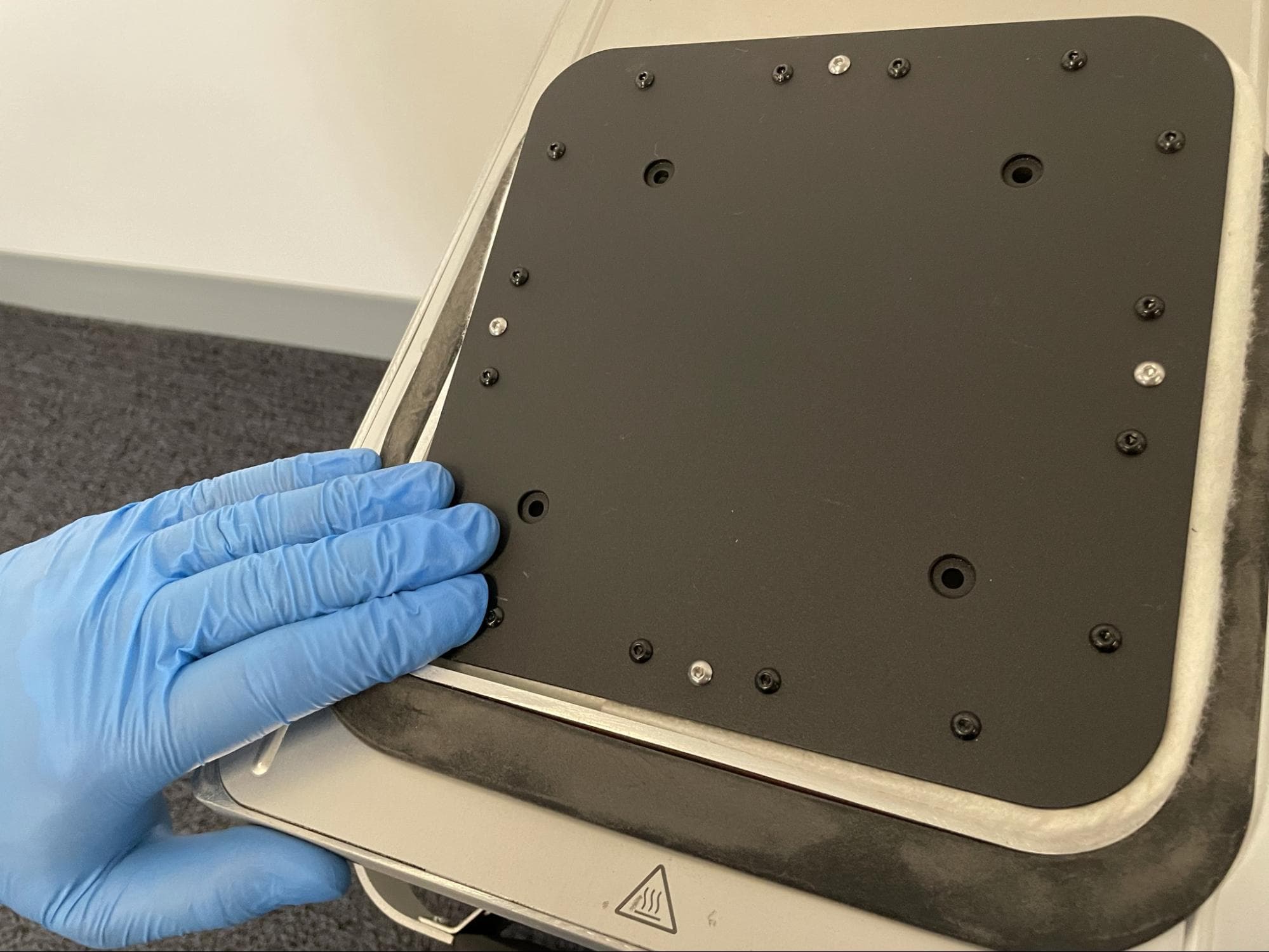
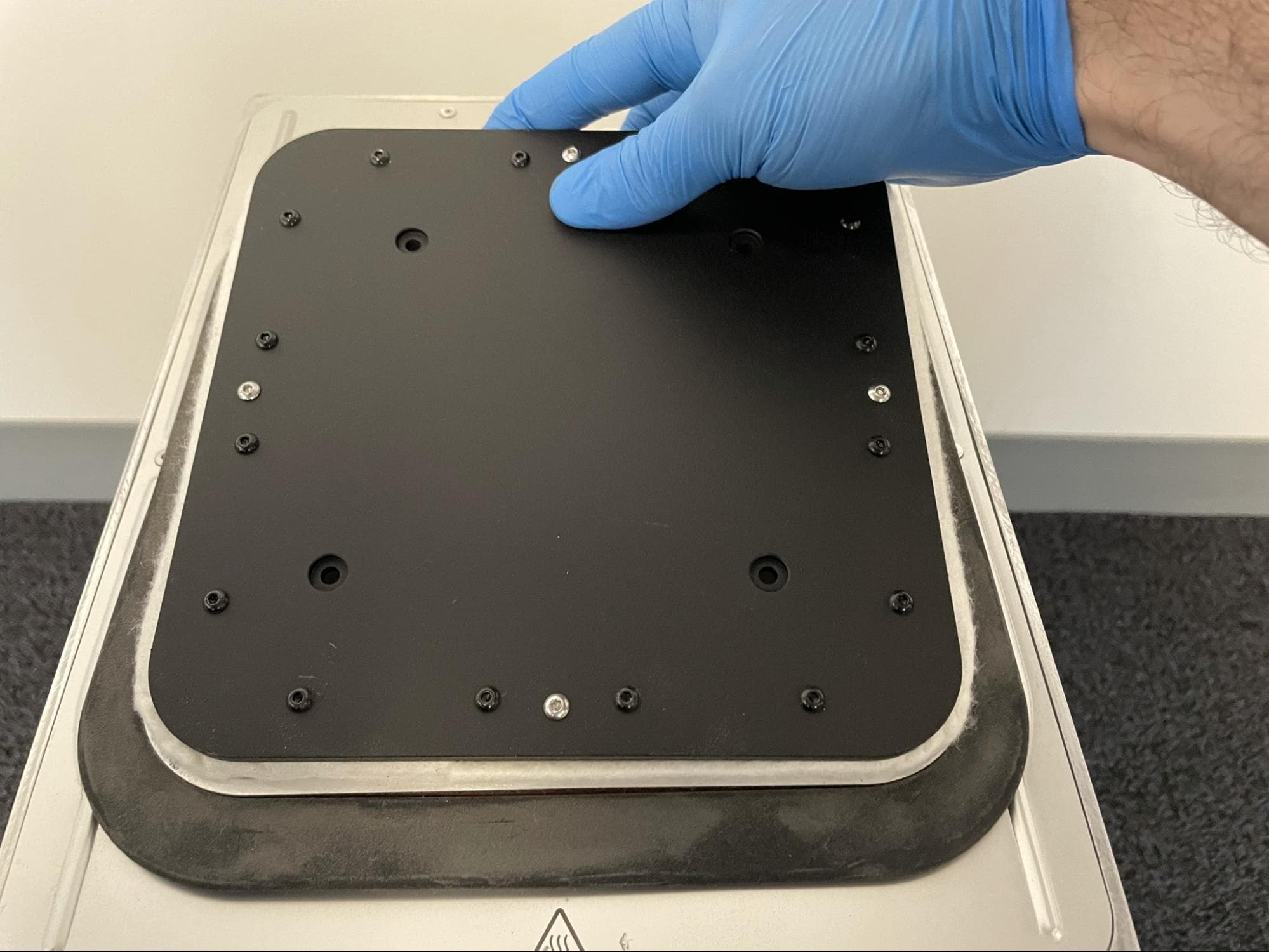
Place the print bed on the piston top with the one bed screw hole that is offset from the other three in the front-left corner.

Step 6: Press the print bed into place

Replace the print bed

Firmly push the print bed into place, one corner as a time. It may be necessary to grab the back of the print bed and push it forward to compress the felt seal while also pushing downward on the front half to seat the print bed.

Step 7: Check the position of the print bed

Replace the print bed

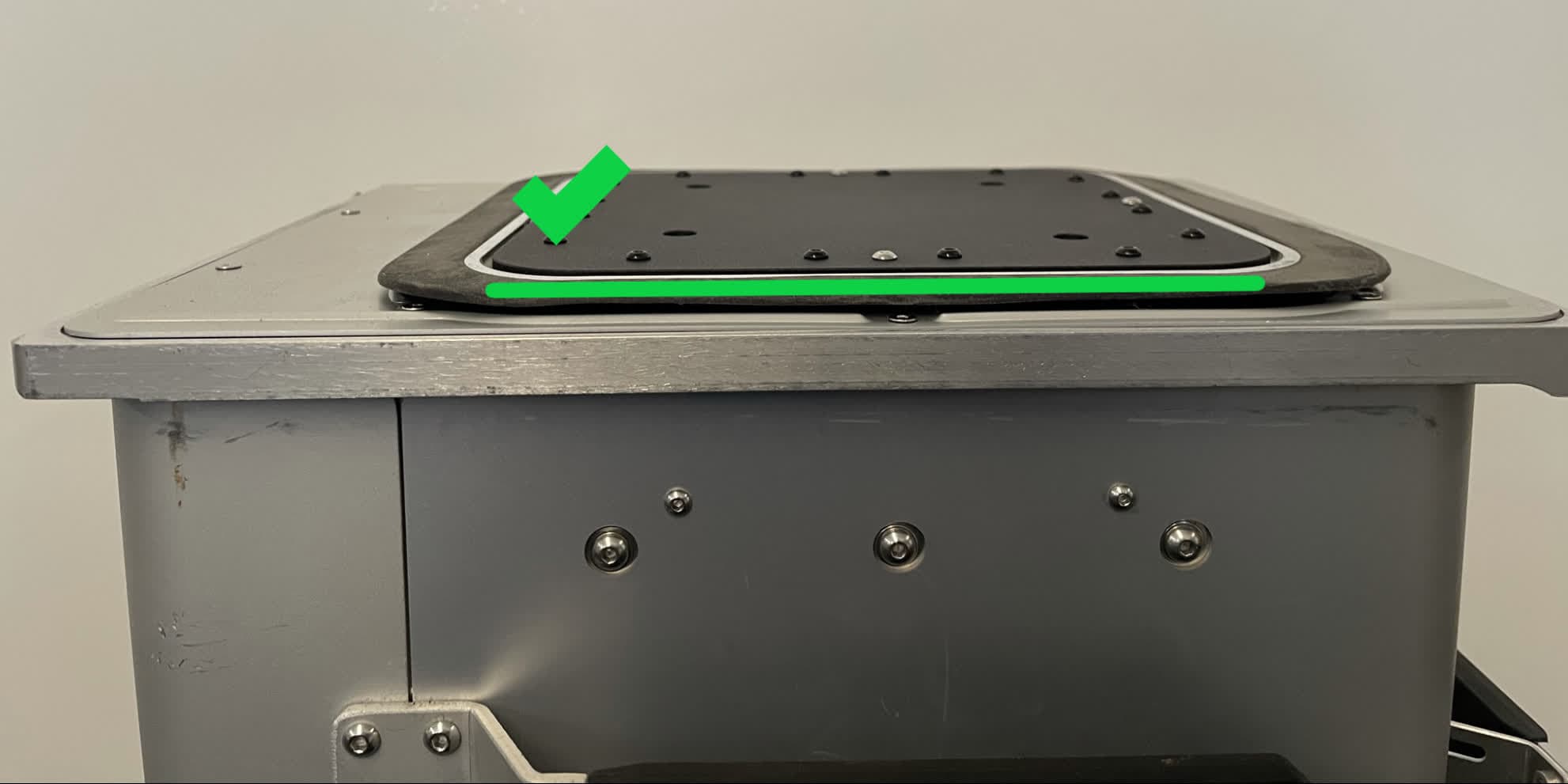
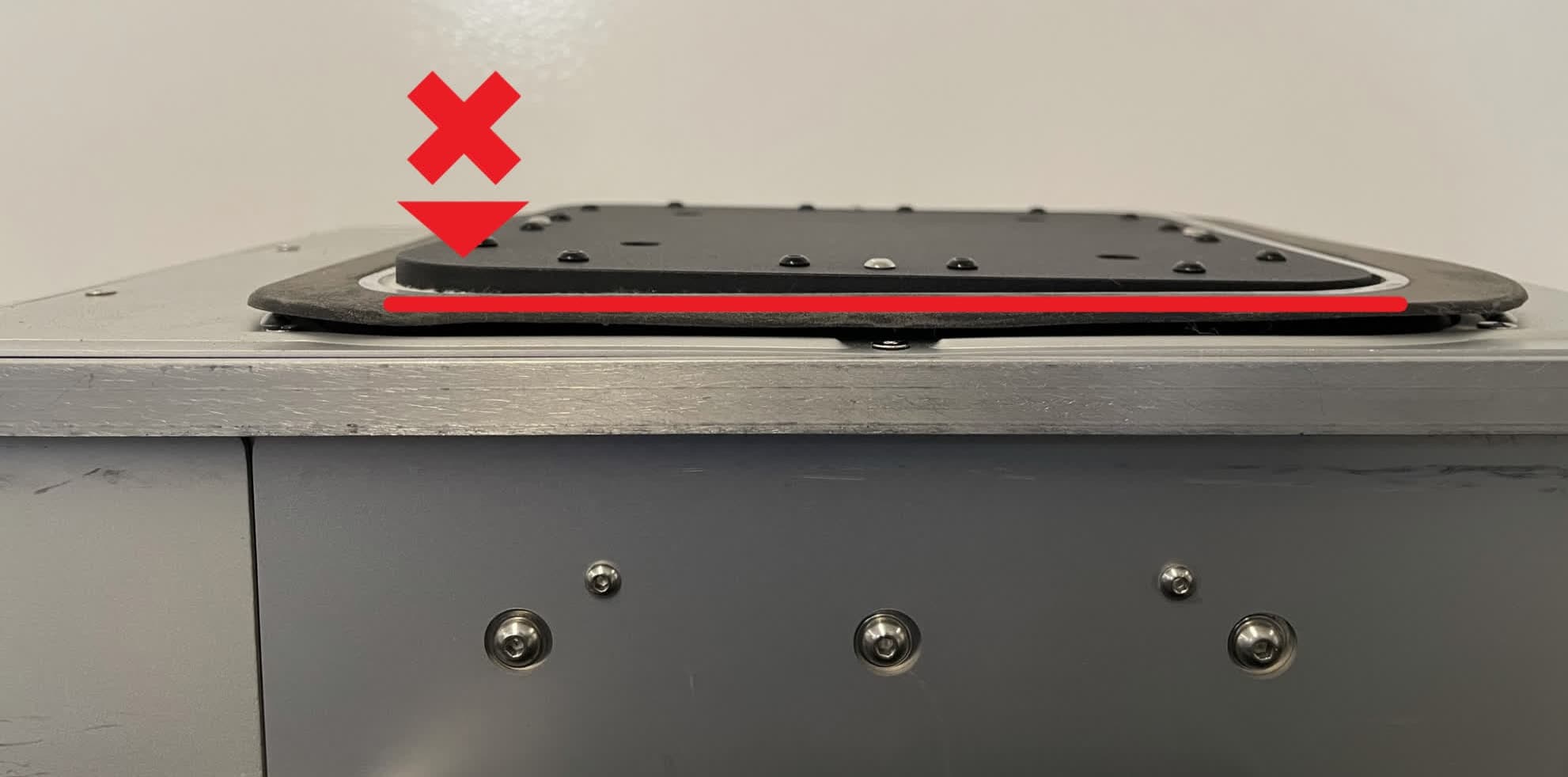
Inspect the print bed to check that it is parallel to the top of the build chamber. If it is slightly askew, check that all four corners are seated by firmly pressing down on each one with the palm of your hand.

Step 8: Secure the print bed

For each of the four 12.0 mm M4 button head print bed screws, apply a small dab (roughly 2–3 mm in diameter) of Loctite 246 or other equivalent threadlocker to the tip of the thread shaft. Allow the drop to roll along the threads but not drip off.

Thread one screw into each of the four screw holes in the print bed, then use a 2.5 mm hex driver to tighten until snug.

Replace the print bed

Finalizing the repair

Overview: After securing the build chamber screws, allow the threadlocker to cure and perform final checks.

Step 1: Allow the threadlocker to cure

Before printing with the build chamber, allow the threadlocker to cure for a minimum of 24 hours.

Step 2: Test the repair

Start a print. Monitor the printer to ensure that the print proceeds normally and that the finished parts are free of defects. Contact Formlabs Support or your certified service provider to share the results of the procedure.