
Required supplies:
Formlabs:
- T20 Torx driver (provided with Fuse Blast)
Third-party:
- N95 respirator mask
- 6.5 mm flat-blade screwdriver
- Static dissipative vacuum

The Fuse Blast media hopper holds 8.3 L (2.2 gal) of blasting media. Overfilling the Fuse Blast may clog the air inlet and prevent the machine from operating correctly. The air metering valve is located at the end of the air inlet hose.
Use this guide to clear a clog in the Fuse Blast air metering valve and air inlet hose.
Required supplies:
Formlabs:
Third-party:
Estimated time: 30 minutes
Warning:
The Fuse Blast is designed to contain fine particulate matter from media blasting and SLS 3D printing. Always wear an N95 respiratory mask when performing maintenance on a Fuse Blast unit.
Preparing the workspace
Overview: Prepare the Fuse Blast and a clean workspace for clearing the air metering valve.
Step 1: Prepare the workspace
Clear a workspace. Ensure that the workspace is well-ventilated, level, and clean.
Step 2: Unplug the machine
Disconnect the power cable from the machine before continuing with maintenance. Do not perform maintenance on the machine while it is connected to power. Wait five minutes after disconnecting the printer from power before proceeding.
Danger:
Performing this repair on the Fuse Blast while it is plugged in increases the risk of electric shock. Never remove any external paneling while the Fuse Blast is plugged in. Never reconnect the Fuse Blast to power while the external paneling is uninstalled.
Step 3: Lift the grate to access the catch chute
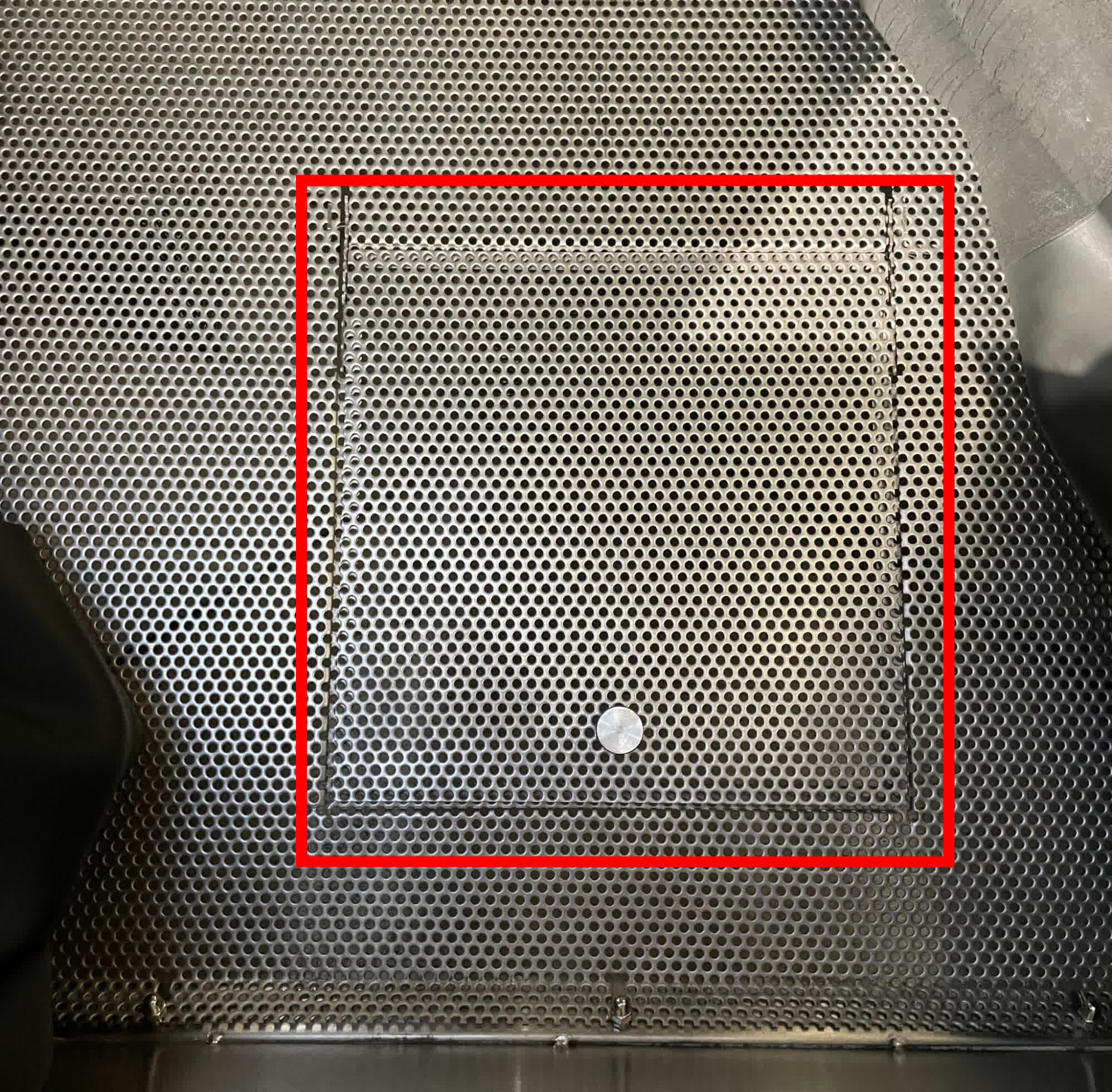
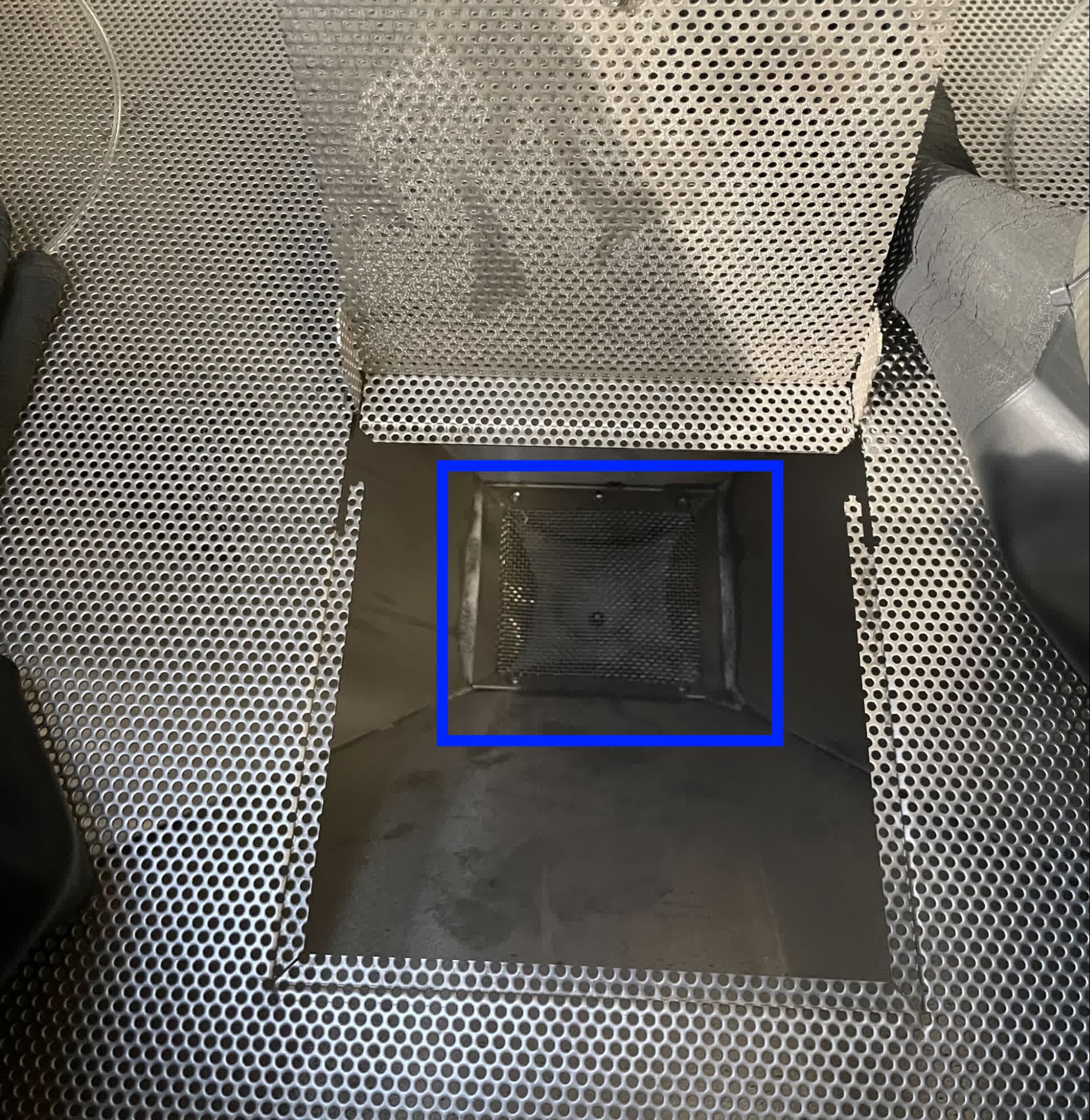
Unlatch and open the blast door to access the work area. Lift the access hatch in the work surface grate and inspect the bottom of the blasting chamber. The parts catcher grate should be visible at the bottom of the chamber.
Step 4: Manually remove the excess powder
Manually scoop out any media, powder, or parts in the parts catcher and set aside. Any remaining loose media will be vacuumed out later in the repair.
Removing the upper sidecar panel
Overview: Uninstall the upper sidecar panel to access the air metering valve.
Notice:
The Fuse Blast contains sensitive electronic components. Ground yourself before touching any electronics in the machine by using an antistatic wrist band or touching a grounded piece of metal.
The air metering valve is located in the sidecar on the right side of the machine. Using a T20 Torx driver, loosen and remove the 12 T20 Torx screws securing the upper sidecar panel to the Fuse Blast. Set the screws aside.
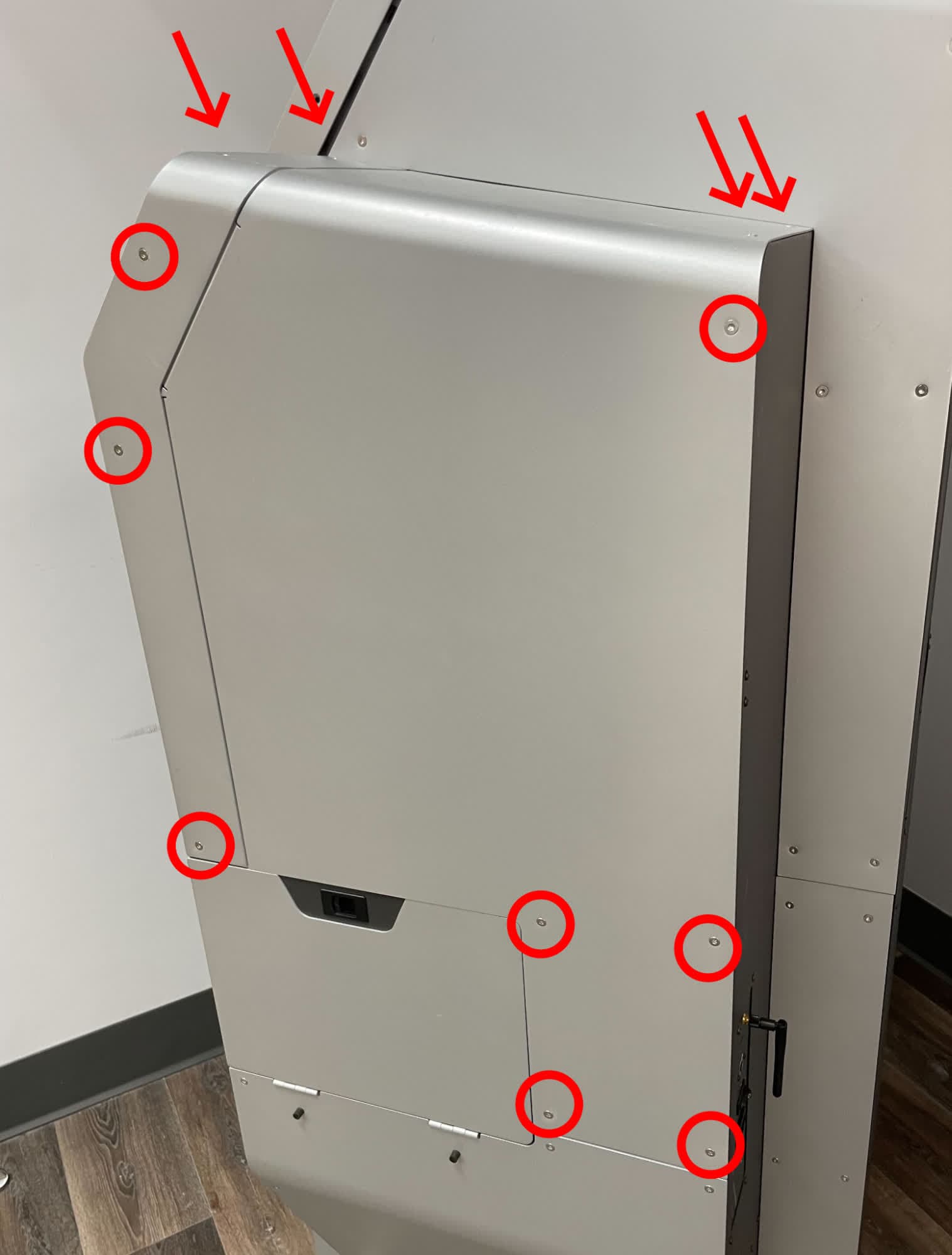
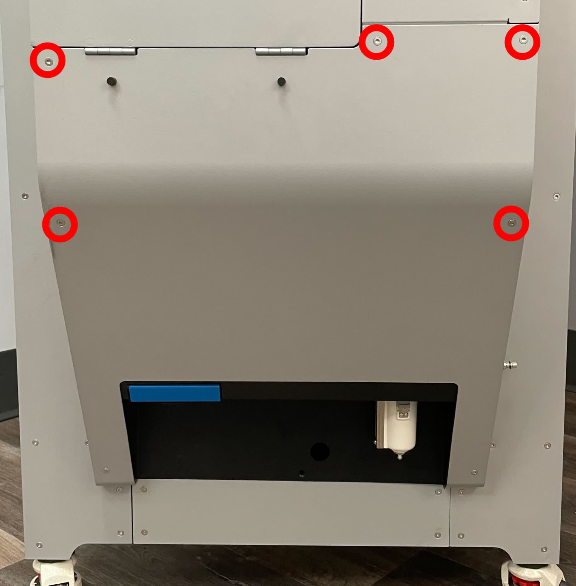
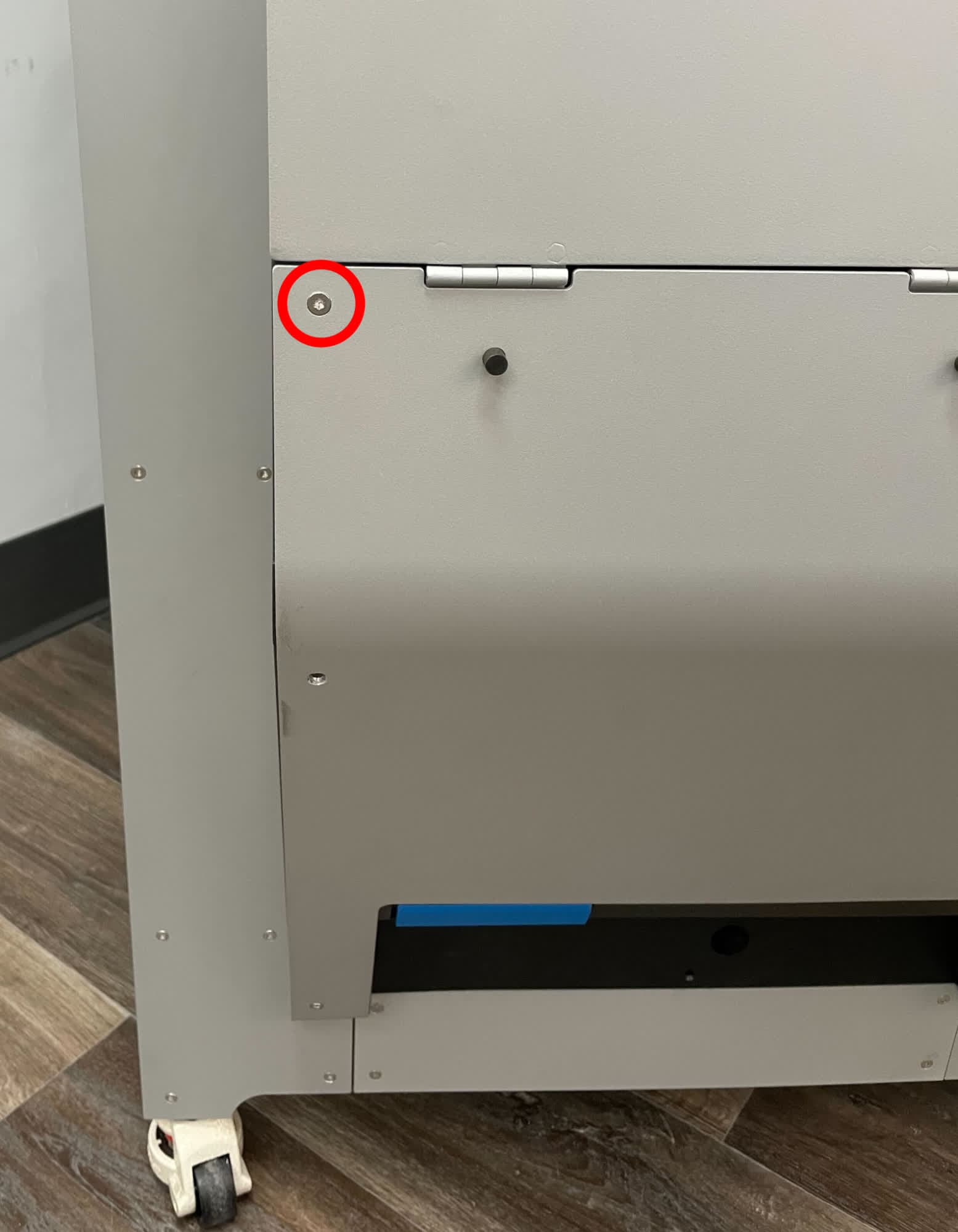
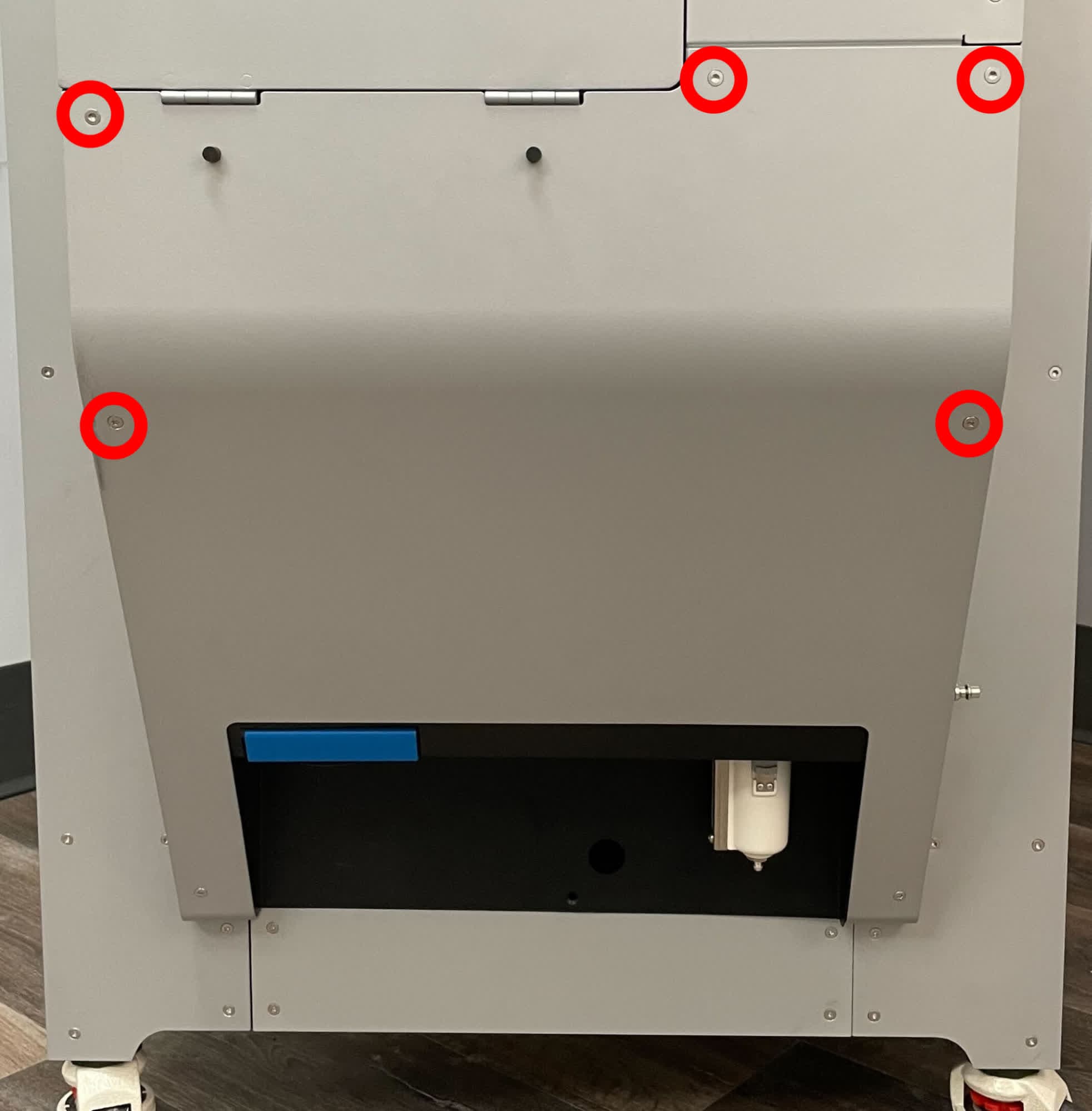
The lower sidecar panel must be moved slightly to free the upper sidecar panel. Using a T20 Torx driver, loosen and remove the five T20 Torx screws shown above. Set the screws aside. Do not remove the two screws at the bottom of the lower sidecar panel.
Step 3: Remove the upper sidecar panel
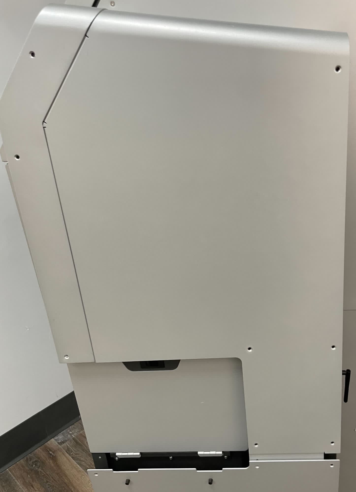
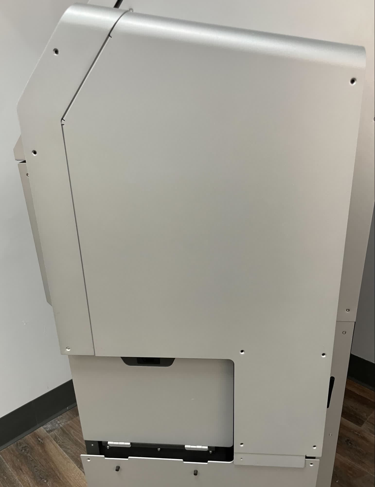
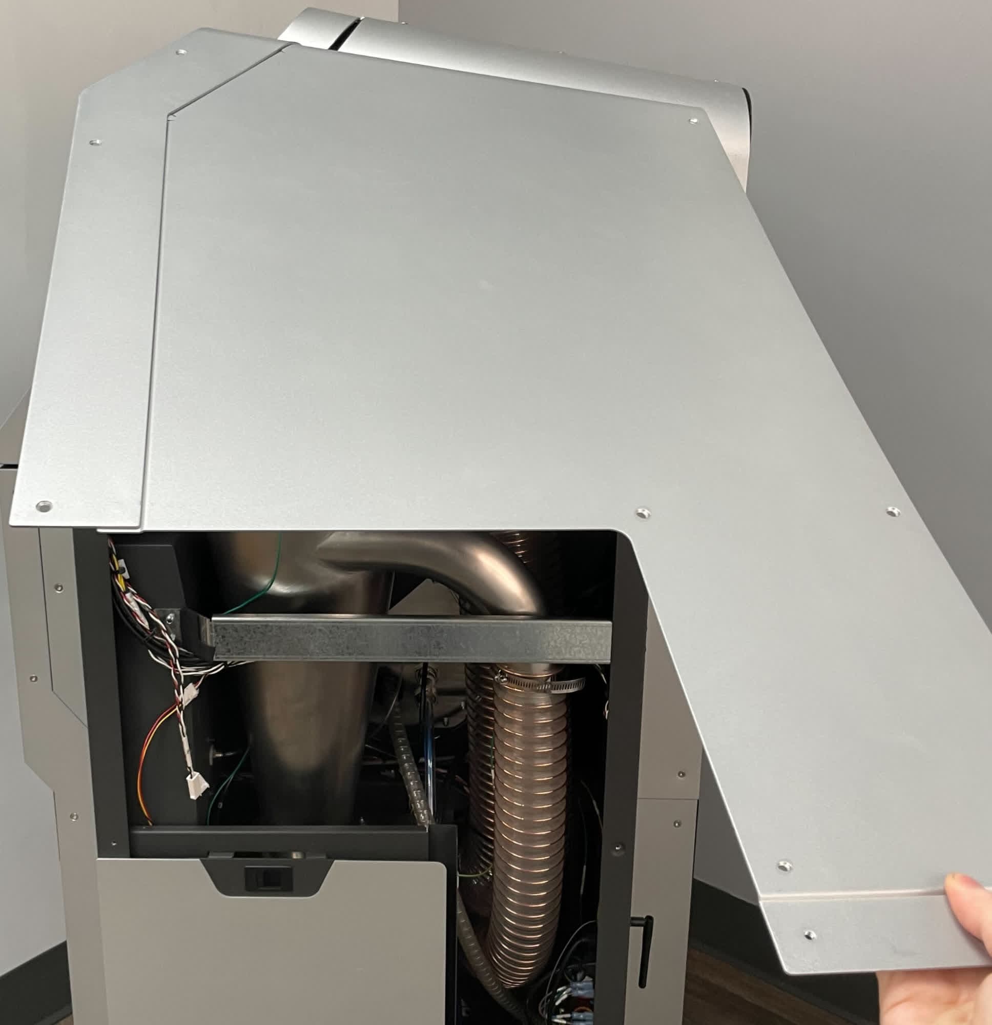
Untuck the bottom of the upper sidebar panel from behind the lower sidecar panel. Rotate the panel upwards until it is horizontal. Once it is horizontal, pull forward to disengage it. Set the upper sidecar panel aside.
Thread at least one of the lower sidecar panel retention screws back into the lower sidecar panel to avoid inadvertently bending it.
Clearing the air metering valve
Overview: Disconnect the cyclone inlet hose to access the clog.
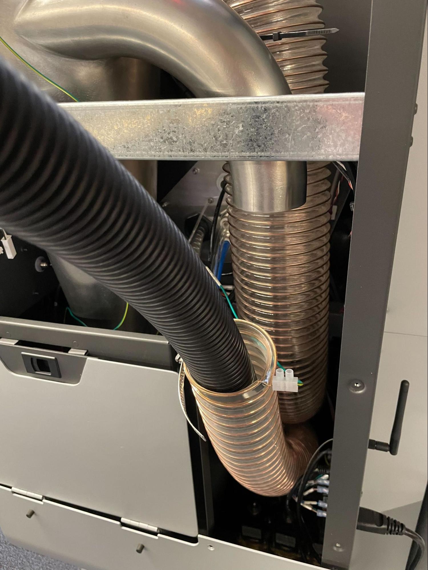
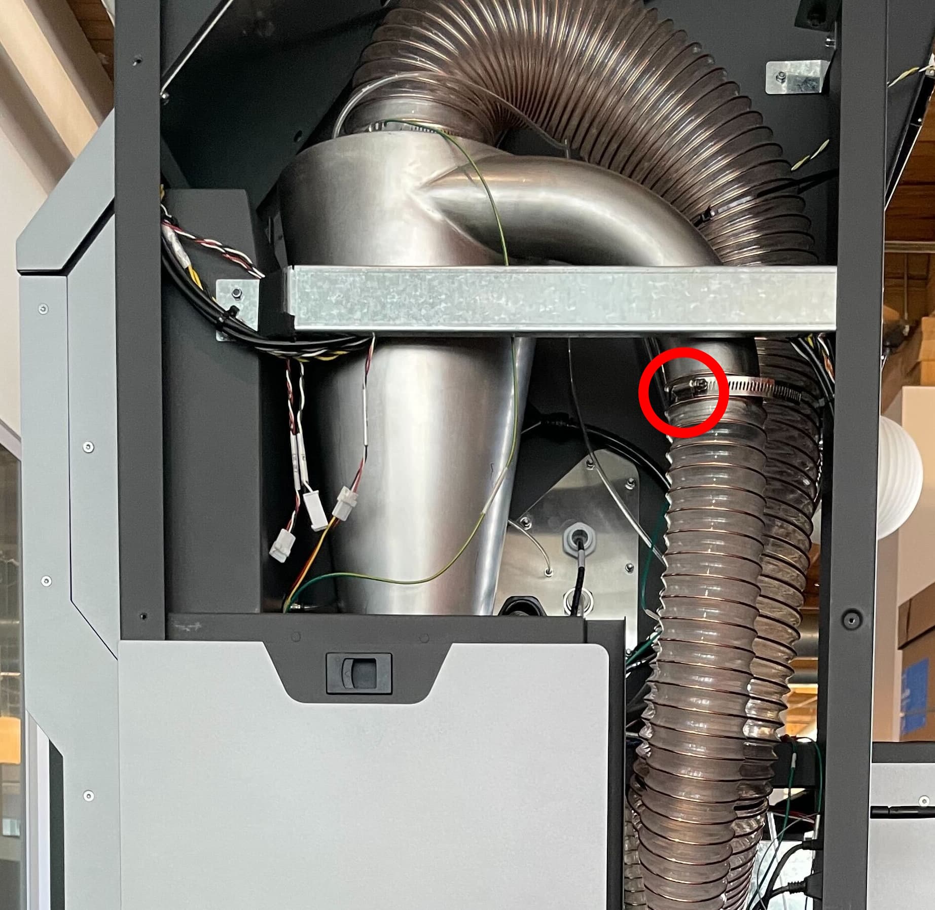
Using a small flat-blade screwdriver, loosen the lower hose clamp from the cyclone separator. Remove the cyclone inlet hose from the cyclone separator.
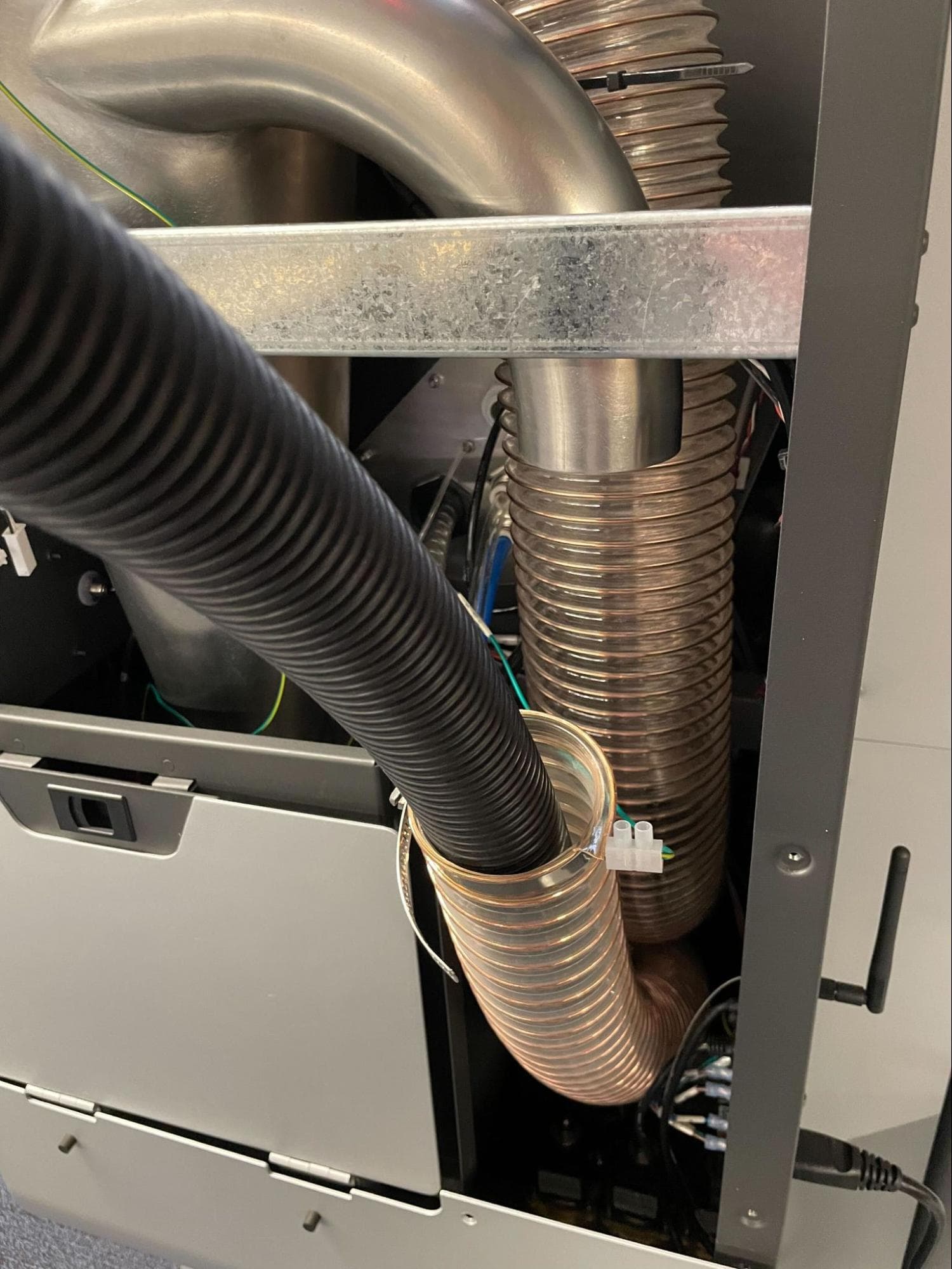
Using a static dissipative vacuum, run the vacuum hose down the inlet tube and vacuum any blockages. Once the blockage is clear, remove the vacuum hose.
Reinstall the inlet hose to the cyclone separator. Tighten the hose clamp using a 6.5 mm flat-blade screwdriver.
Reinstalling the upper sidecar panel
Overview: Reinstall and secure the upper sidecar panel.
Use a T20 Torx driver to loosen and remove any lower sidecar panel retention screws you previously reinstalled. Set the screws aside. Do not remove the two screws at the bottom of the lower sidecar panel.
Step 2: Mount the upper sidecar panel
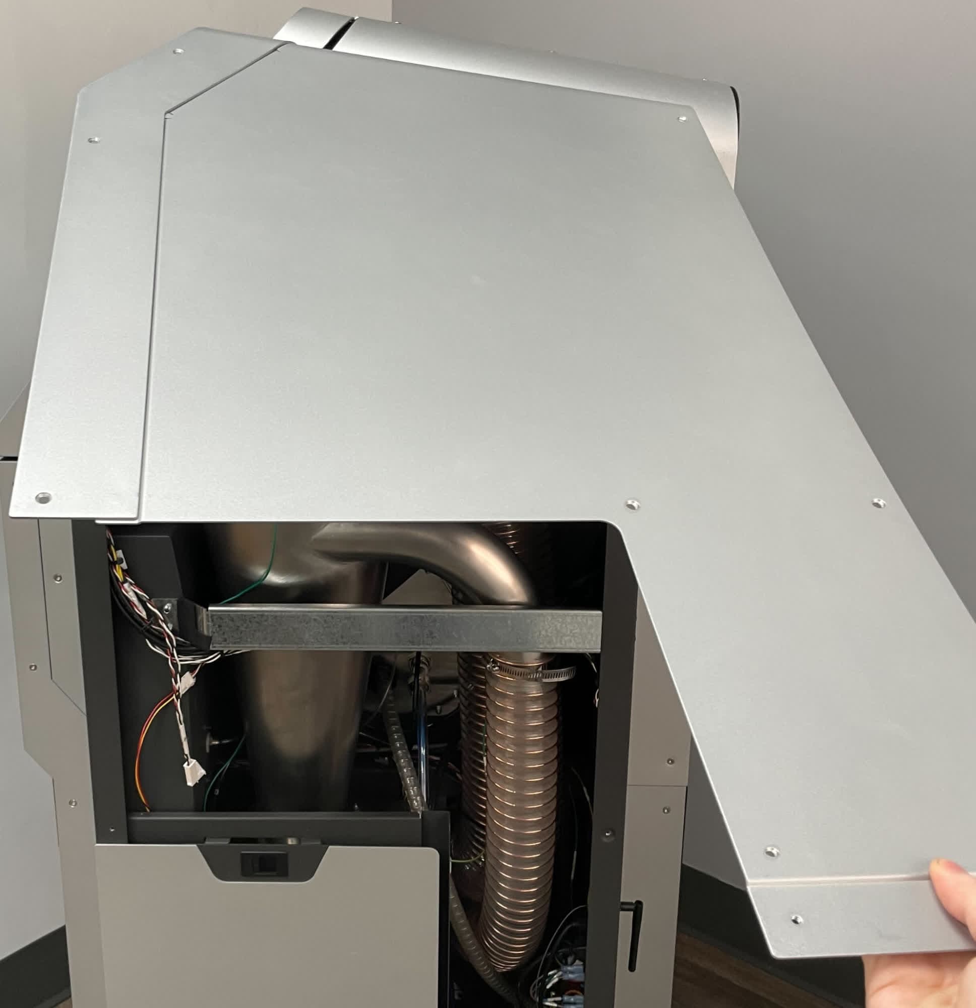
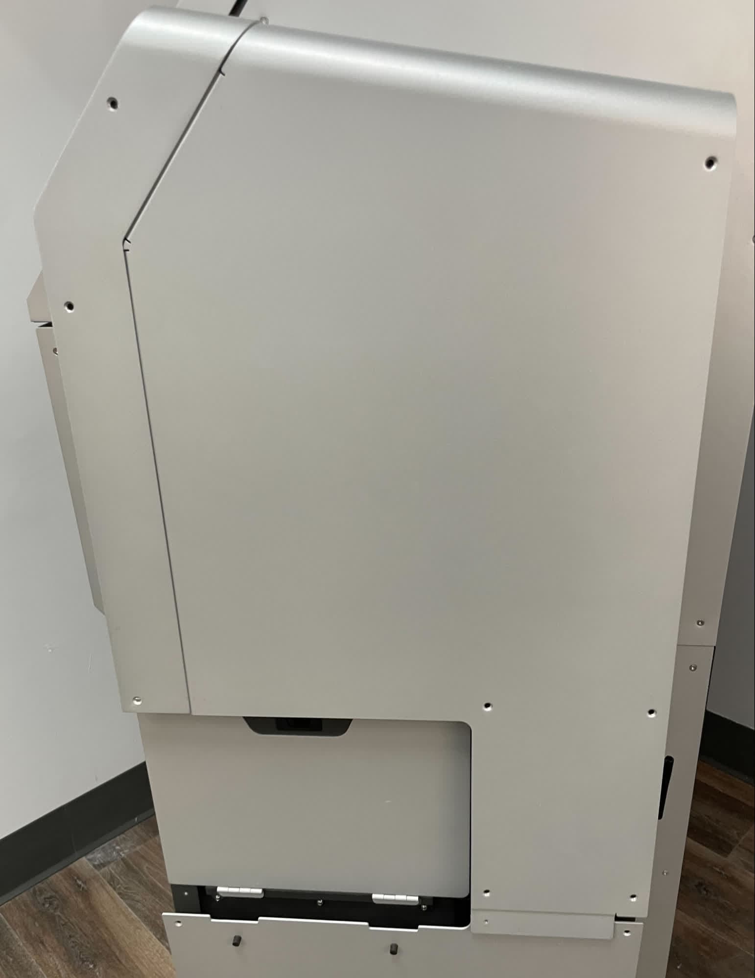
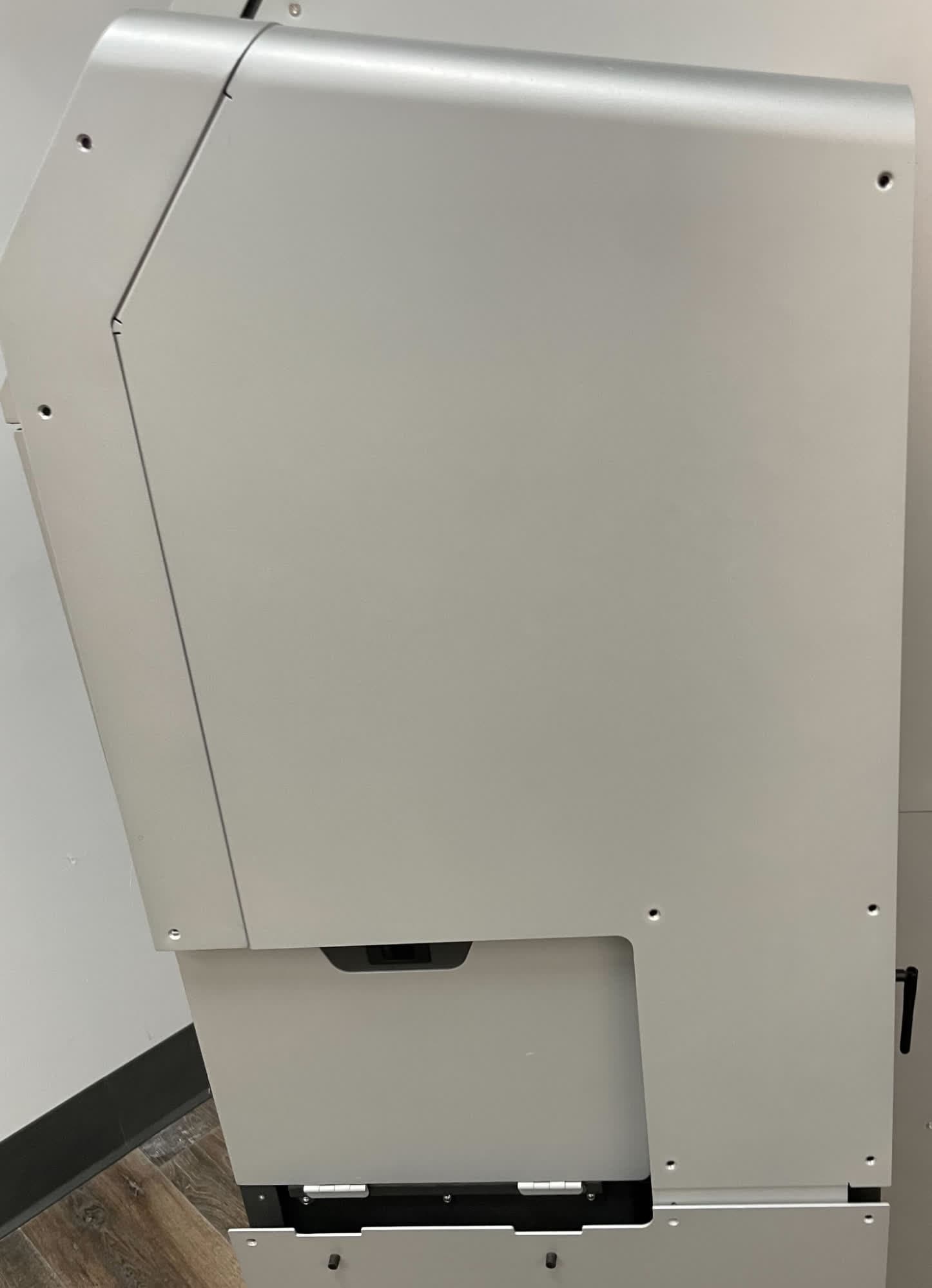
Insert the upper sidecar panel horizontally such that the flange tucks under the upper panel. Rotate the sidecar panel downward, then tuck the lower flange under the lower sidecar panel.
Thread one upper sidecar panel retention screw into each of the 12 screw holes in the upper sidecar panel. Use a T20 Torx driver to tighten until snug.
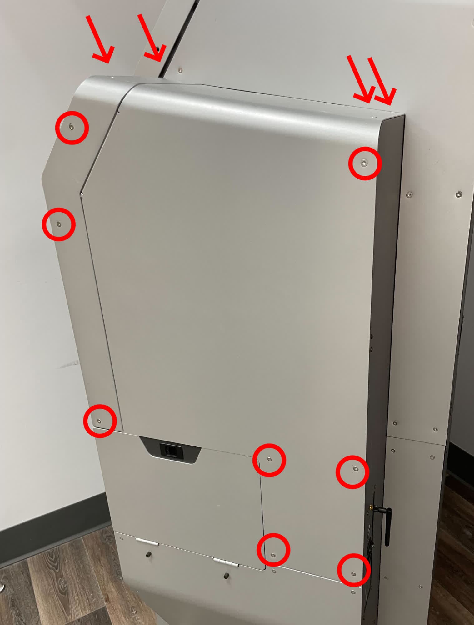
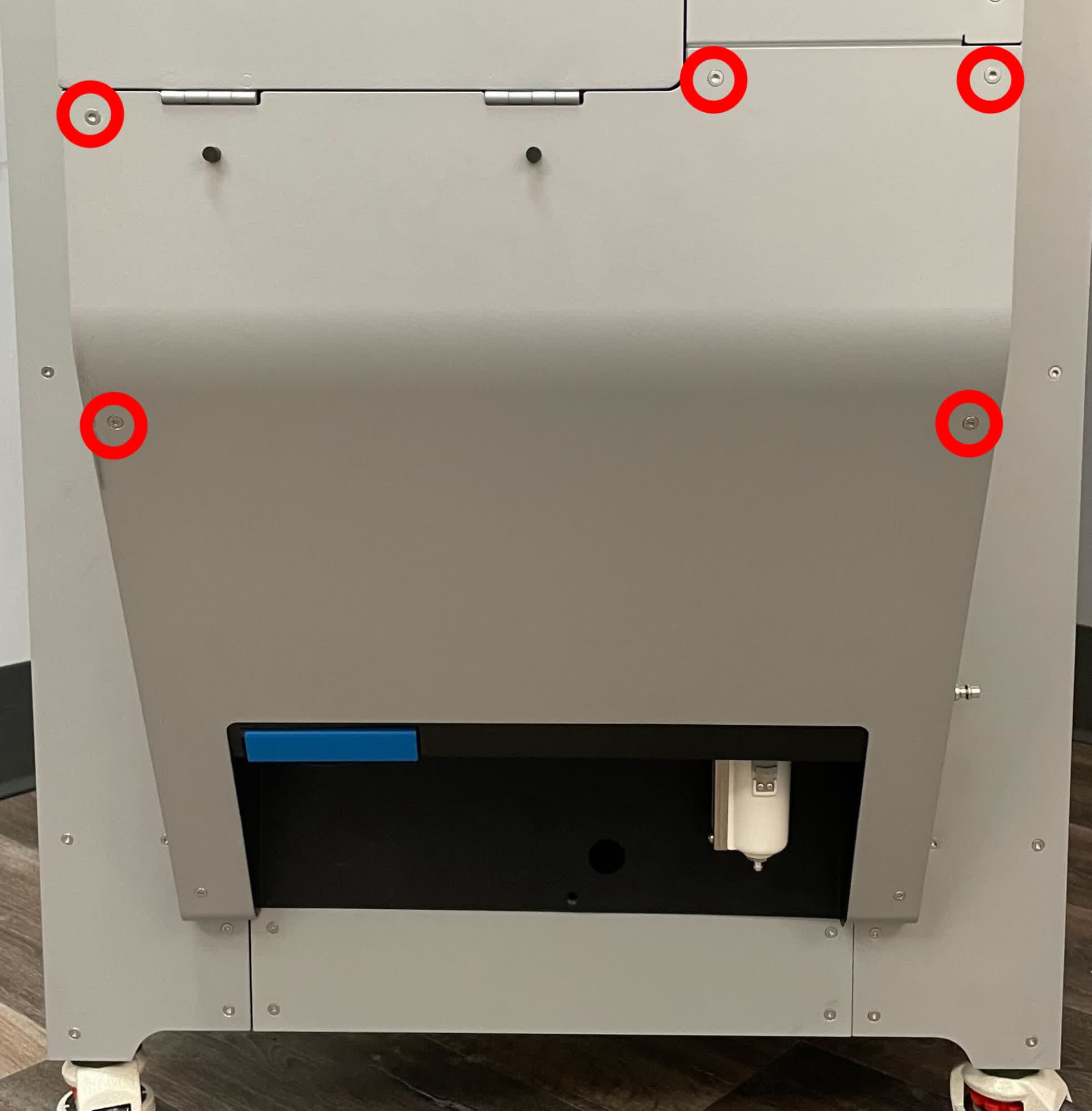
Thread one upper sidecar panel retention screw into each of the five open screw holes in the lower sidecar panel. Use a T20 Torx driver to tighten until snug.
Finalizing the repair
Overview: After clearing the clogged air metering valve, power on the machine and perform final checks.
Step 1: Power on the machine
Connect the power cable to the machine and the power supply. Flip the power switch on the back of the machine to the ON position. The machine initializes.
Step 2: Test the repair
Test the machine to ensure that it operates normally. Activate the blast gun, either manually or by starting an automatic blasting cycle. Check that blasting media flows from the blast gun normally. Do not overfill the machine with blasting media to prevent future blockages.