WHITE PAPER
Formlabs Logo

Design guidelines and custom supports for Silicone 40A Resin

Design guidelines and custom supports for Silicone 40A Resin

Printing with elastomeric resins can present an additional risk of print failures. Follow Formlabs best practices to maximize print success with Silicone 40A. You may wish to design custom tearaway supports for parts printed with Silicone 40A, which allow you to eliminate support marks and reduce post-processing time.

Notice:

To learn more about the performance or specific material properties of Silicone 40A Resin, refer to the Safety Data Sheet (SDS) and Technical Data Sheet (TDS). Always consult the SDS as the primary source of information to understand safety and handling of Formlabs materials.

Best practices for designing with Silicone 40A Resin

For best results, follow the guidelines below when designing and printing parts with Silicone 40A Resin. See the Model comparisons section below for examples.

Expanding areas

When possible, avoid orientations that increase the cross-sectional area of the model as the print progresses. Orient the part with the largest layers closest to the build platform.

Customer tearaway supports

Designing custom support structures as part of the model geometry can improve surface finish and print success.

Build platform parallelism and cleanliness

Maintain your printer and build platform to reduce the number of print failures related to build platform non-adherence.

  • Recalibrate and fine tune your printer’s Z-axis to correct non-adherence.
  • After washing your printed parts and removing them from the build platform, spray the build platform with isopropyl alcohol and scrub dry with a paper towel. Residual washed silicone and butyl acetate can reduce the adhesion of future prints.

Printing on the build platform with supports

Printing on the build platform gives the model a solid base and reduces the number of required support touch tips. When possible, set Raft Type to None for models printed directly on the build platform.

Edge profile when printing on the build platform

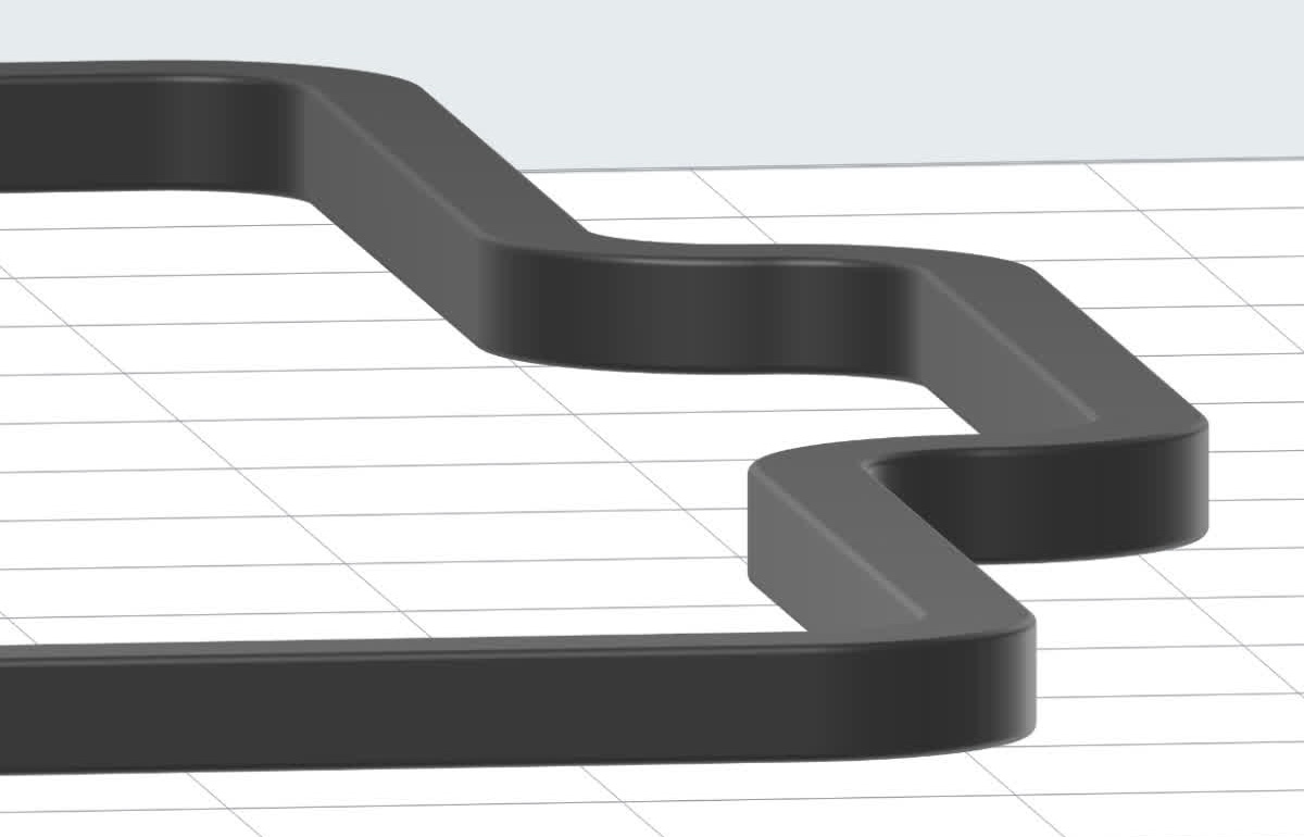
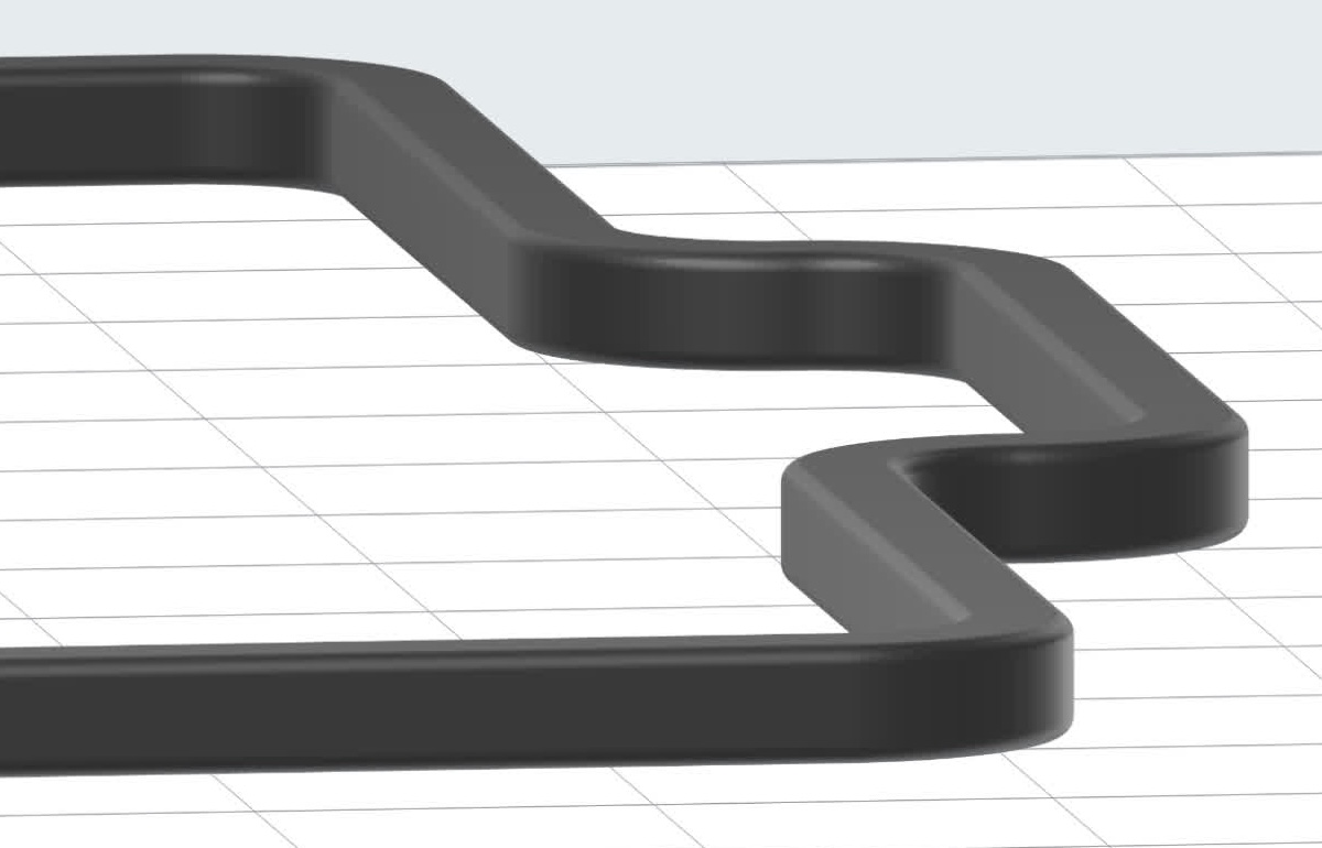
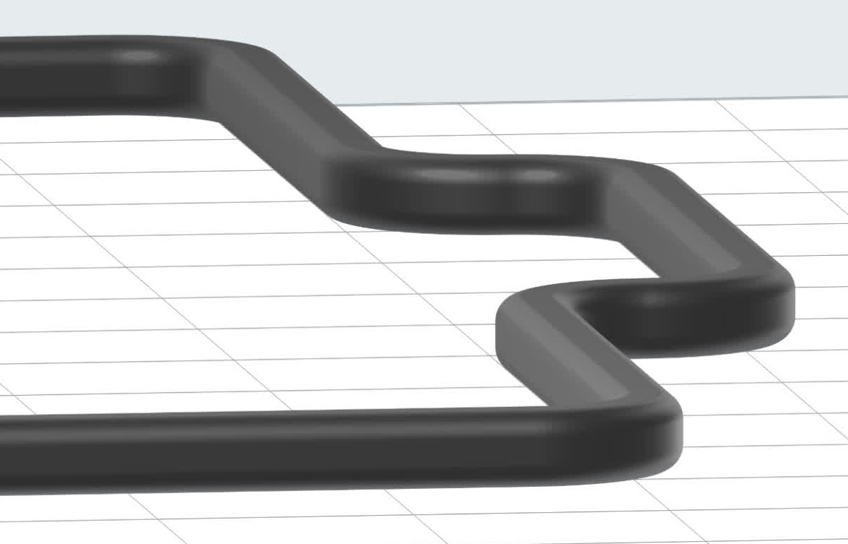
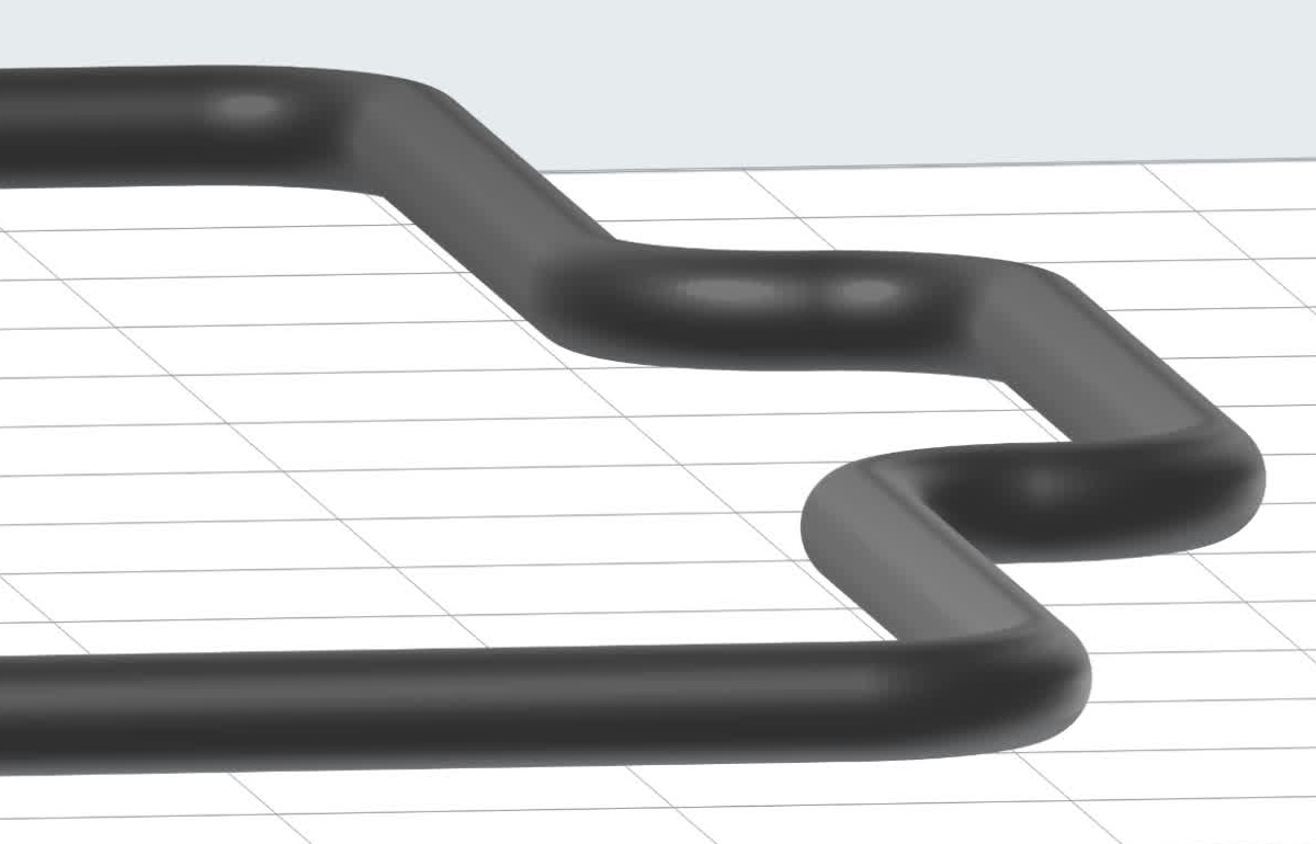
When printing directly on the build platform, consider the edge profile of your model. Models with no radius or a small radius around their base print more reliably than those with a larger radius. Download the models for the examples below to examine in more detail or print them yourself.


ProfilePrintabilityExample
No radius
Download model (STL)
GoodModel showing edge profile with no radius
Small radius
Download model (STL)
GoodModel wshowing edge profile with small radius
Medium radius
Download model (STL)
Likely to printModel wshowing edge profile with medium radius
Large radius
Download model (STL)
Likely to failModel wshowing edge profile with large radius
Full radius/round
Download model (STL)
Will failModel wshowing edge profile with full radius

Examples of custom-designed tearaway supports

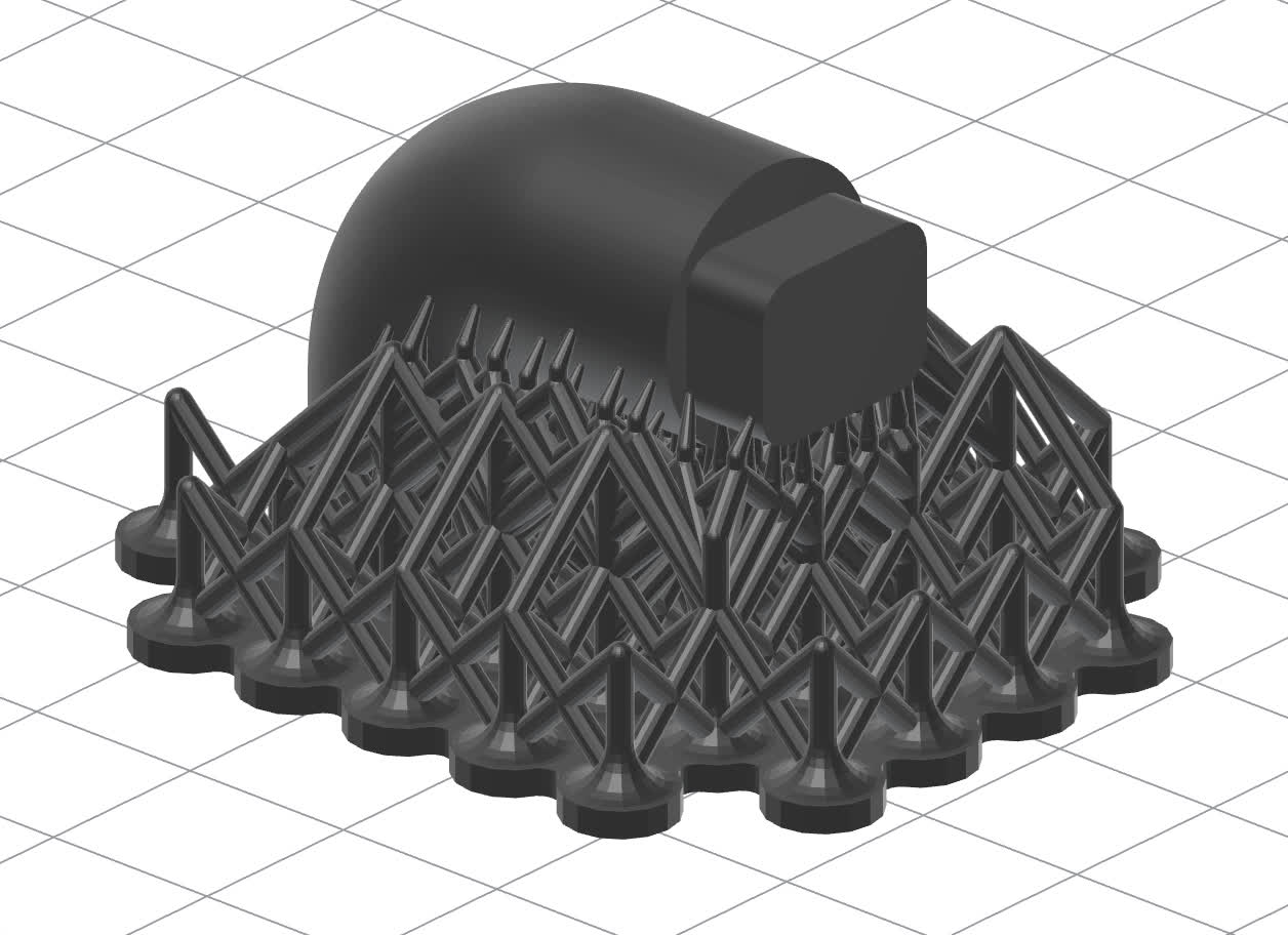
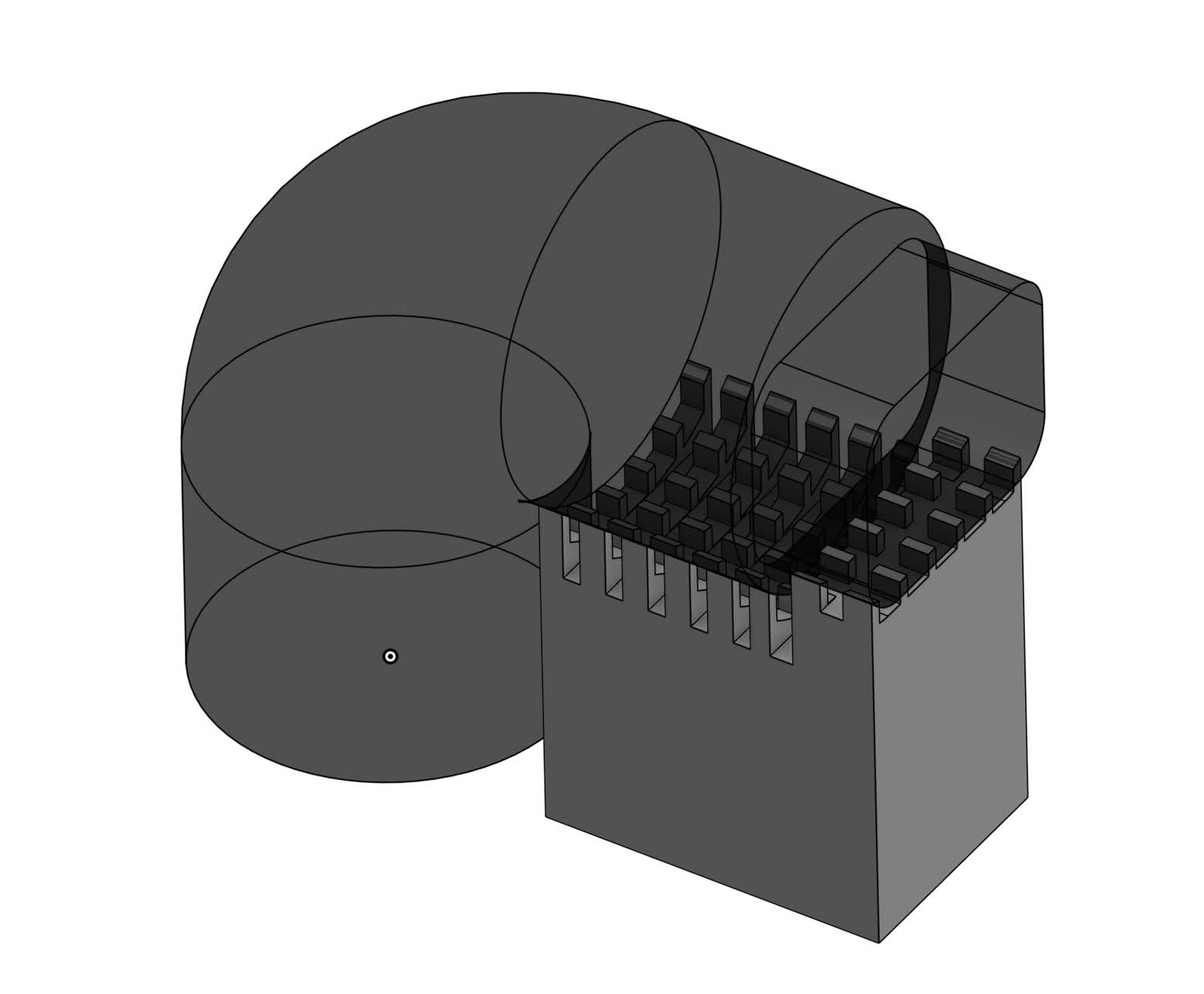
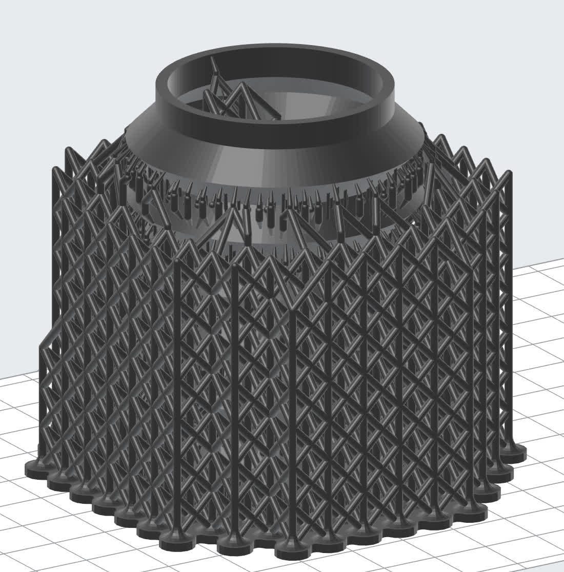
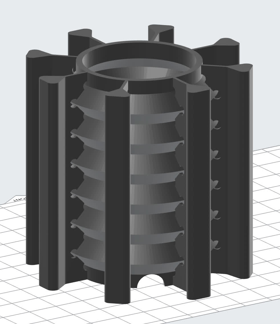
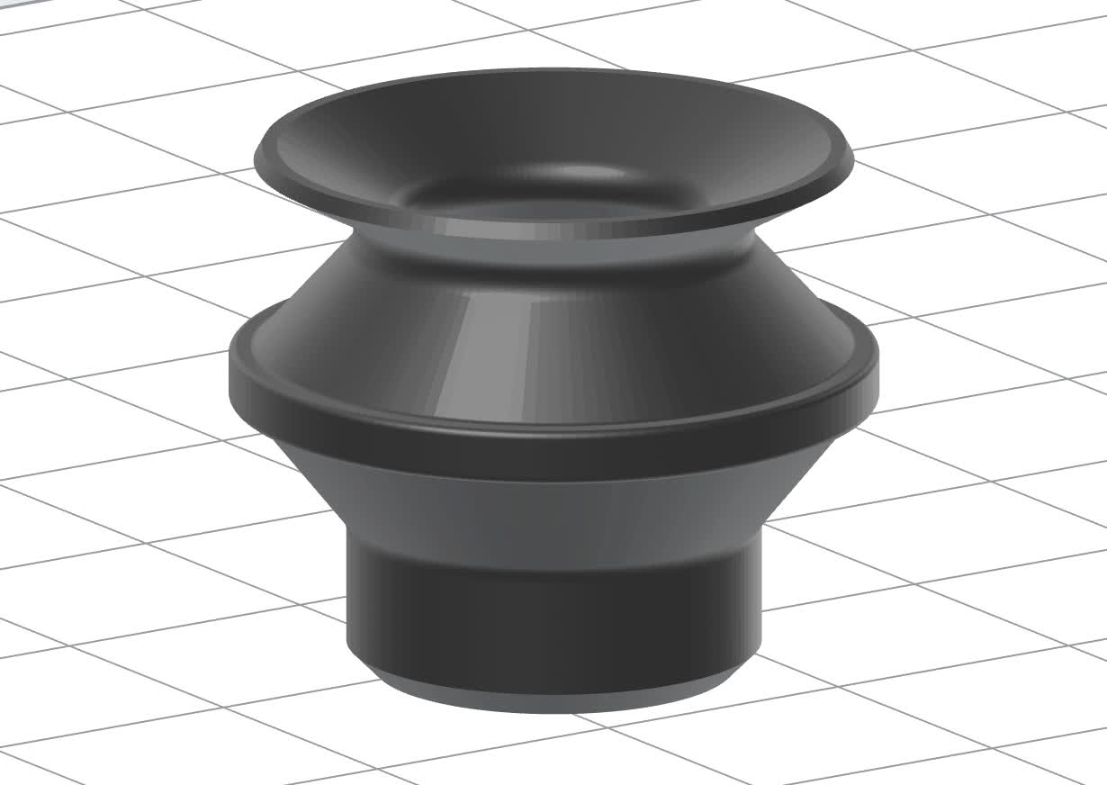
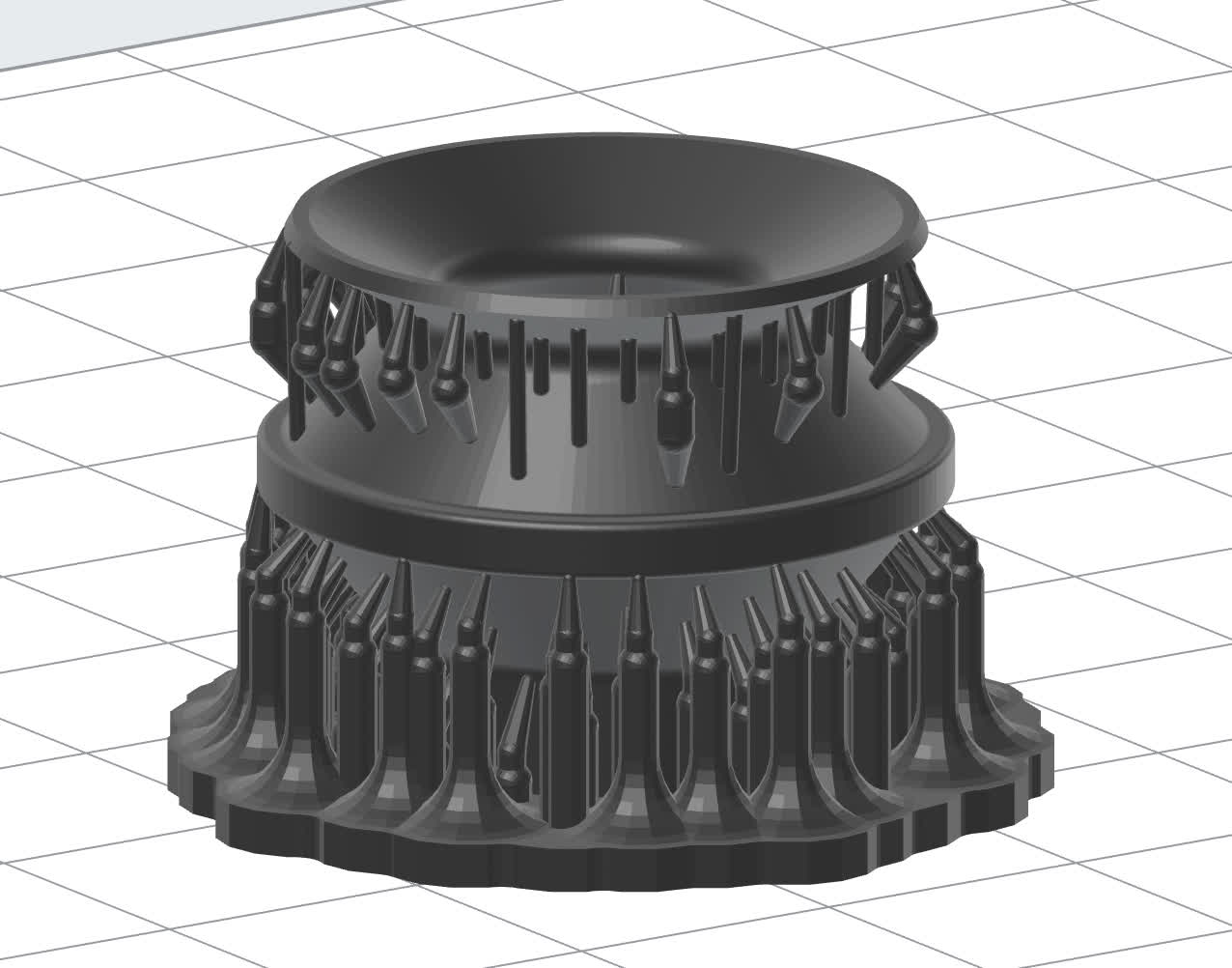
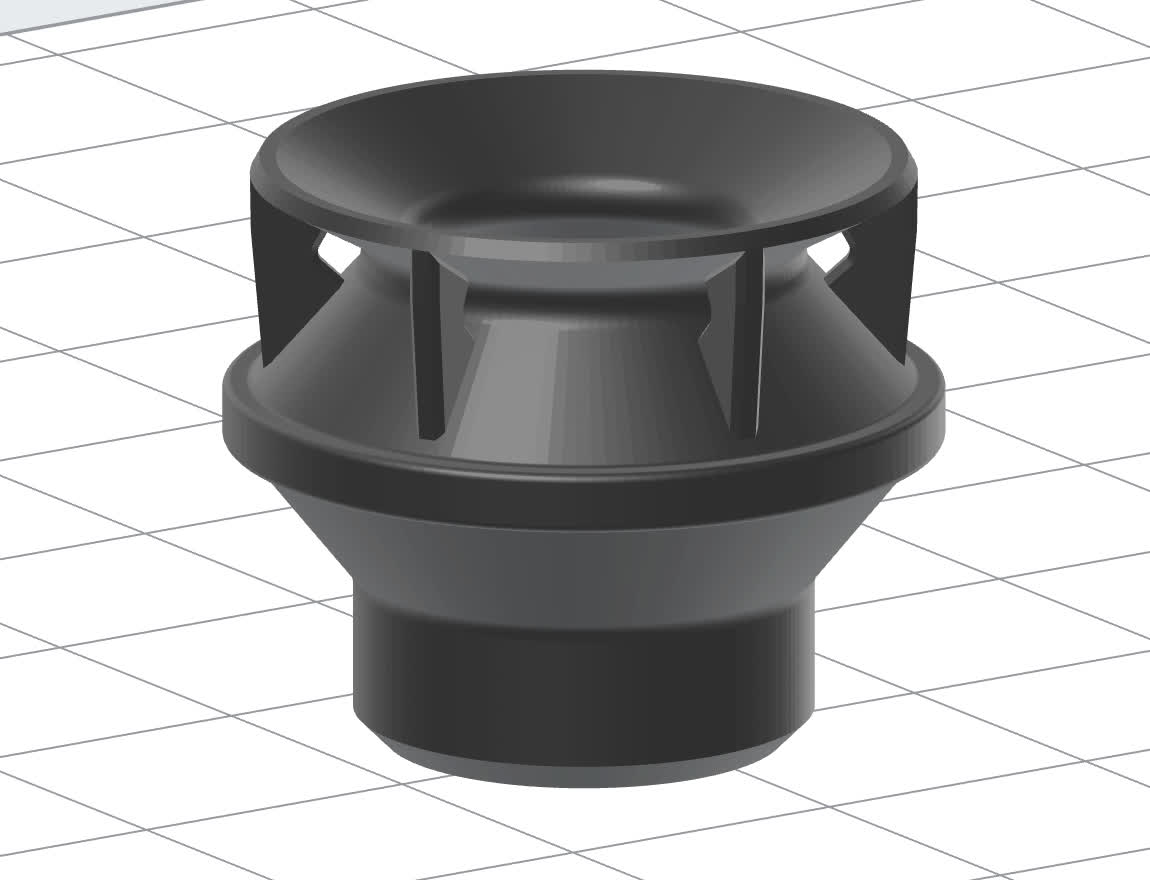
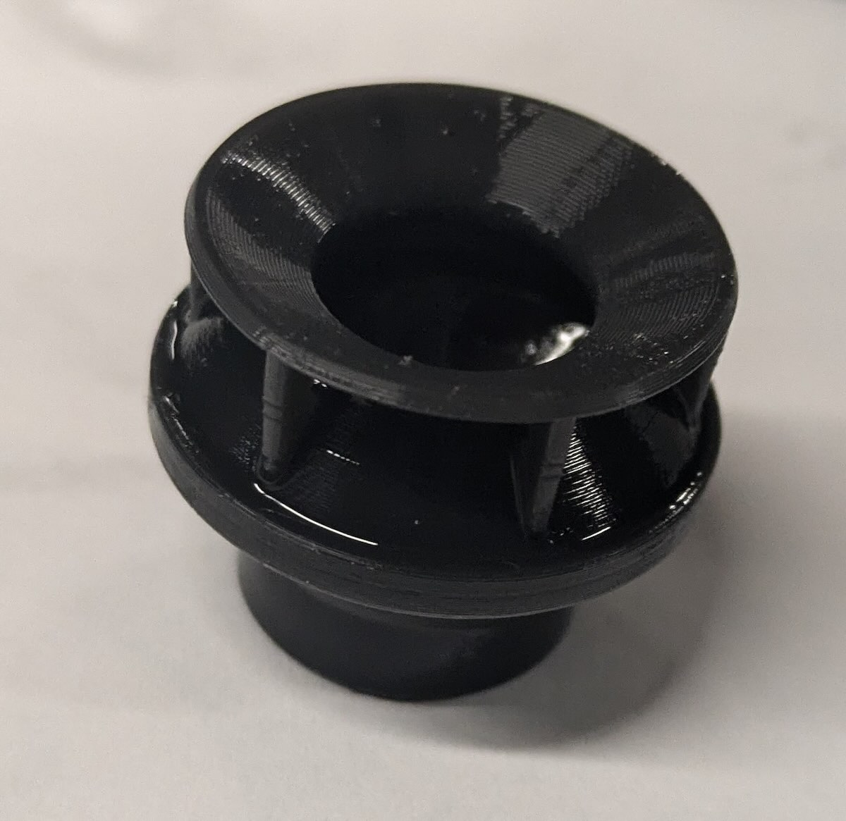
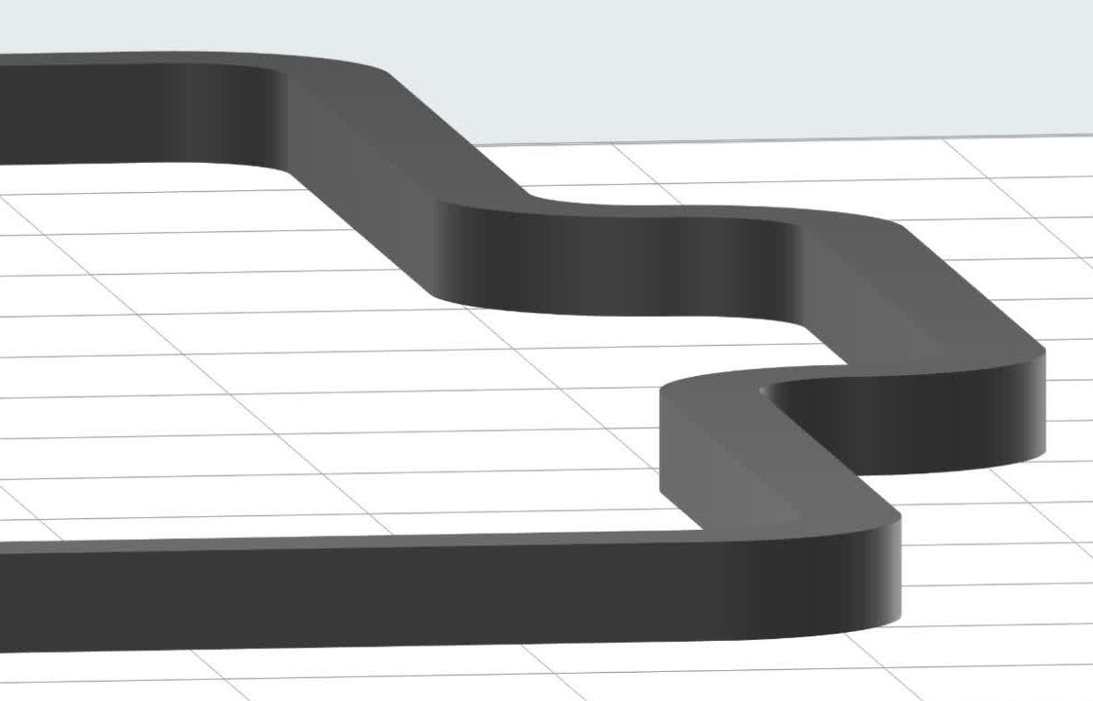
This table compares different representative silicone part models, how PreForm supports them, and how you can support them with custom-designed support structures. Custom supports can be removed with flush cutters, resulting in surfaces with minimal ridgelines instead of numerous small touchpoint artifacts, enhancing surface quality. Download the models for the examples below to examine in more detail or print them yourself.
Original part geometryAuto-generated supports
(less preferable option)
Custom-designed supports
(more preferable option)
Final part printed directly on build platform
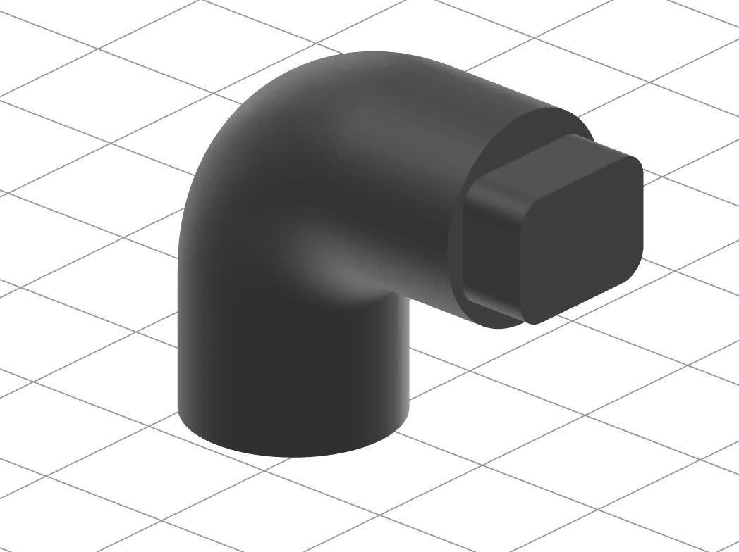
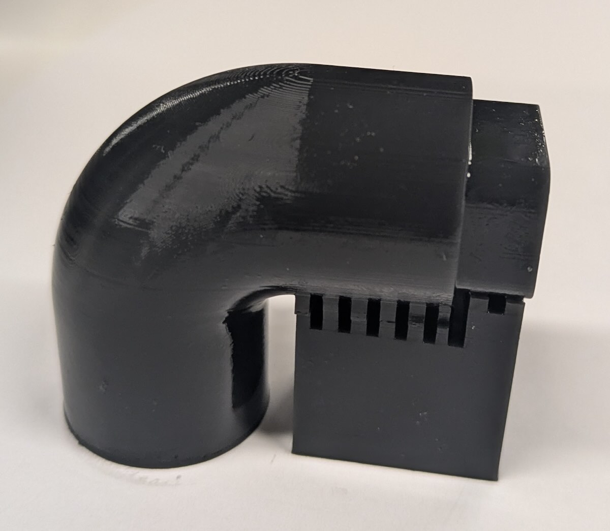
Silicone 40A Resin elbow modelSTLSilicone 40A Resin elbow model with auto-generated PreForm supportsSilicone 40A Resin elbow model with custom supportsSTL | STEPSilicone 40A Resin elbow printed part
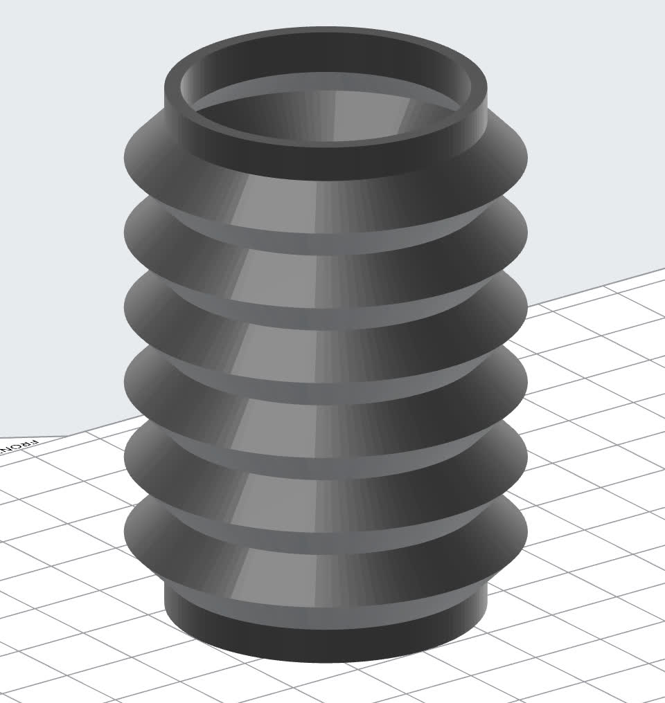
Silicone 40A Resin bellows modelSTL

Note: Bellows-like models are very flexible and do not print well without supports, even if they are well-adhered to the build platform. They stretch and compress between layers, leading to ripping and poor layer registration.

Silicone 40A Resin bellows model with auto-generated PreForm supportsSilicone 40A Resin bellows model with custom supportsSTL | STEP

Note: This model includes a vent hole at the base.

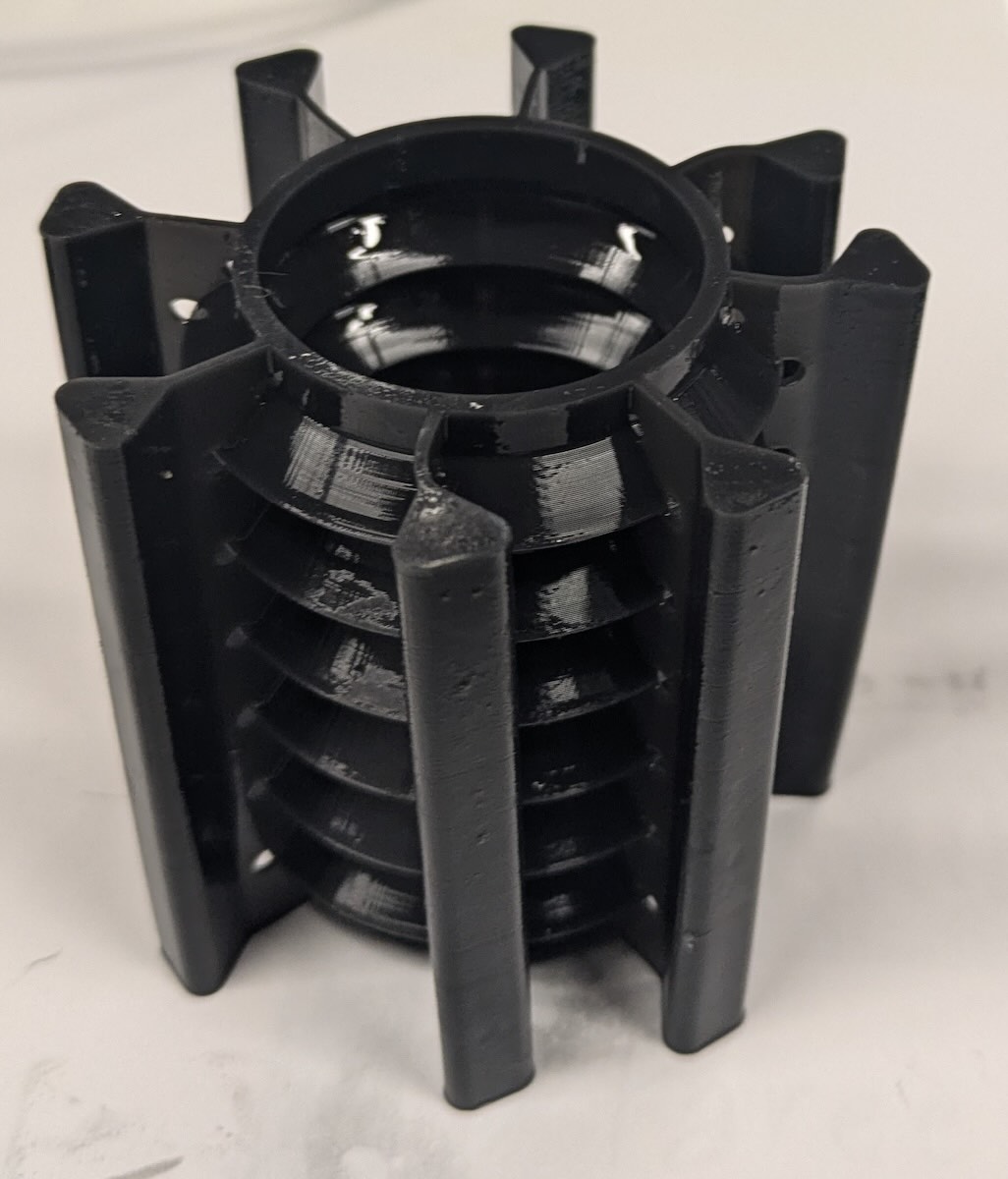
Silicone 40A Resin bellows printed part
Silicone 40A Resin standoff modelSTEPSilicone 40A Resin standoff model with auto-generated PreForm supportsSilicone 40A Resin standoff model with custom supportsSTL | STEPSilicone 40A Resin standoff printed part
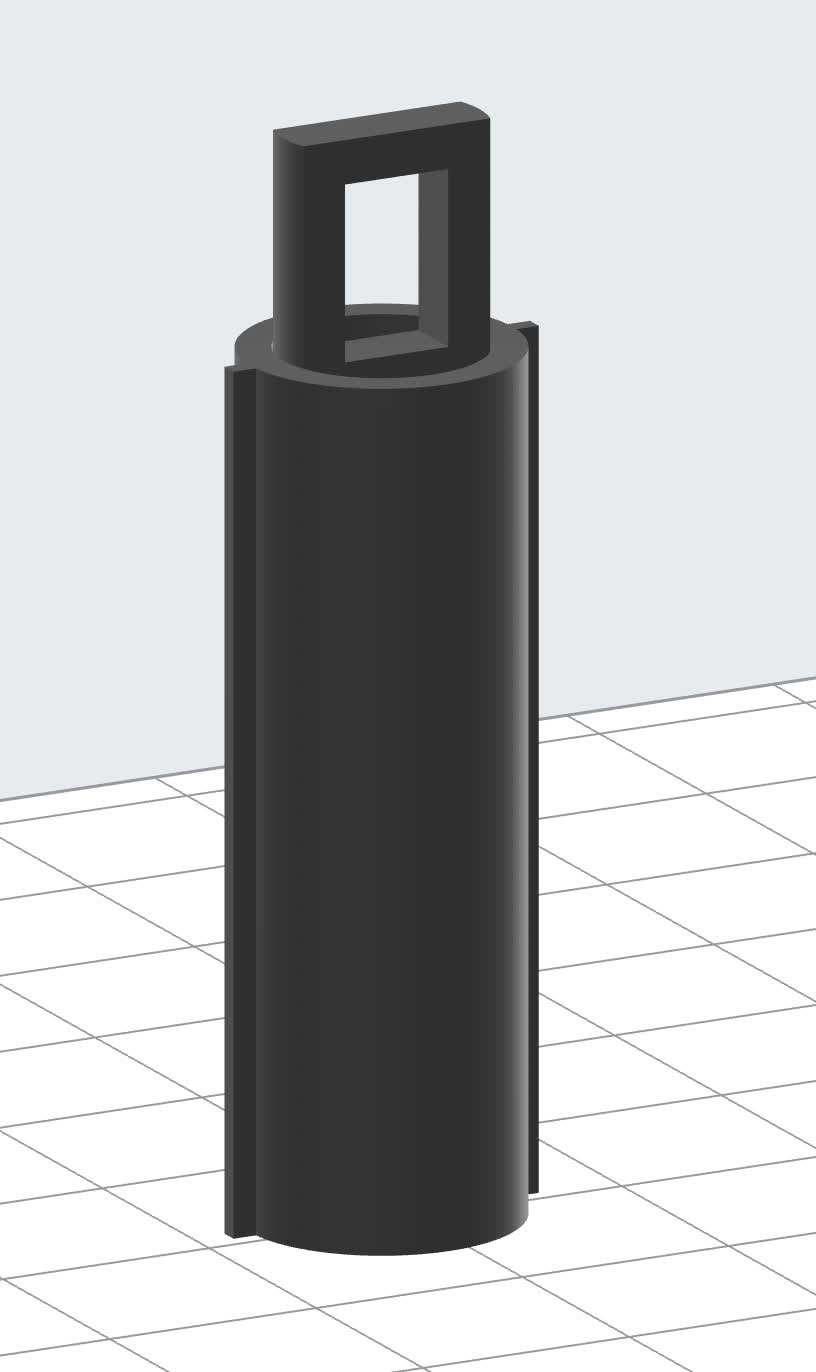
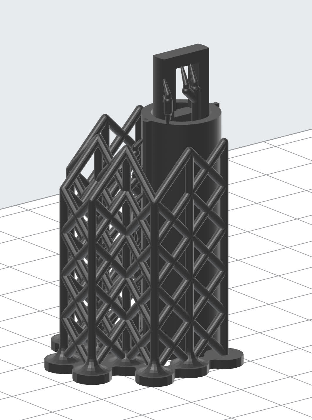
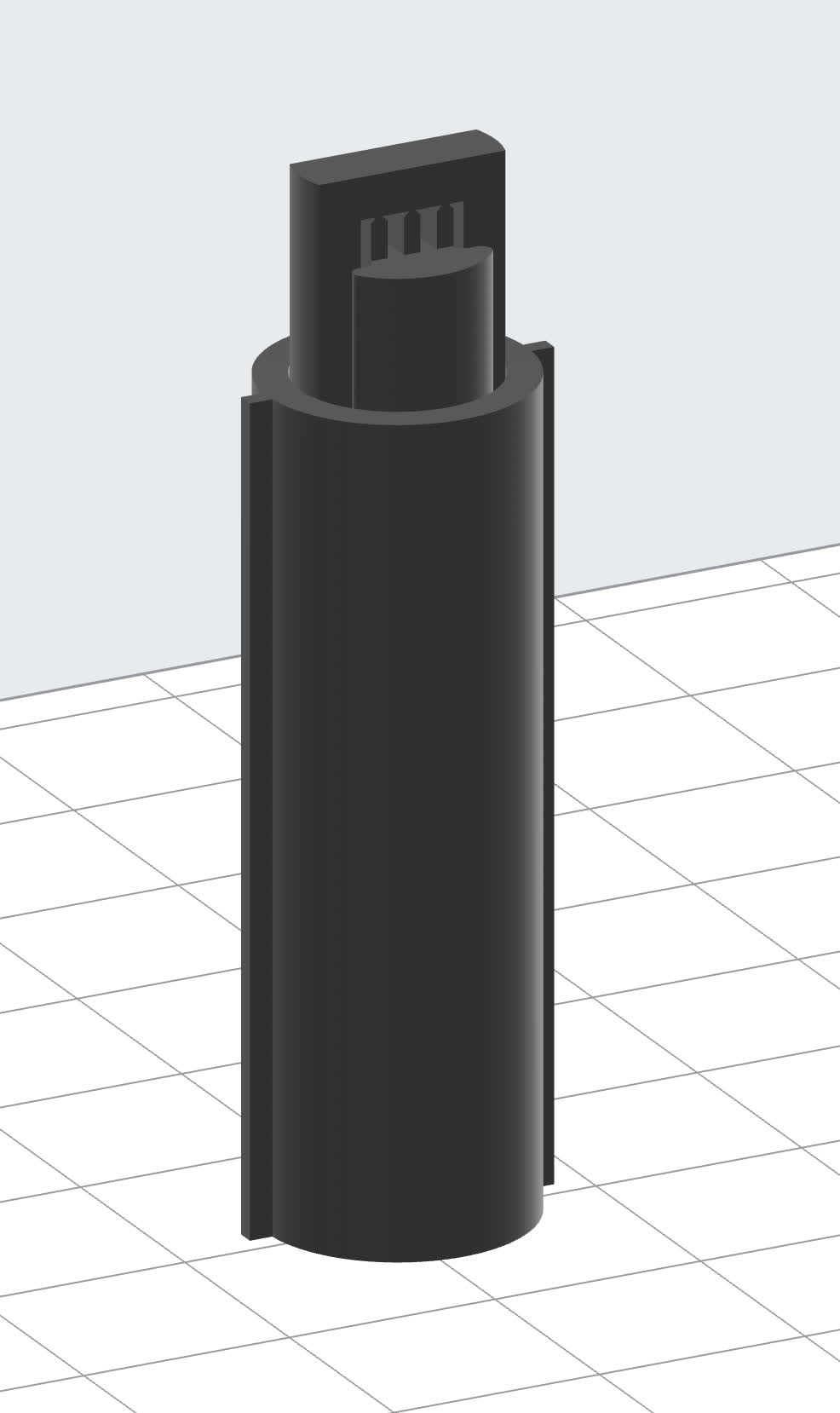
Silicone 40A Resin cylinder modelSTL | STEPSilicone 40A Resin cylinder model with auto-generated PreForm supportsSilicone 40A Resin cylinder model with custom supportsSTL | STEP

Note: This custom CAD support structure comes up though the inside of the model before bridging through the middle at the end to support the overhang.

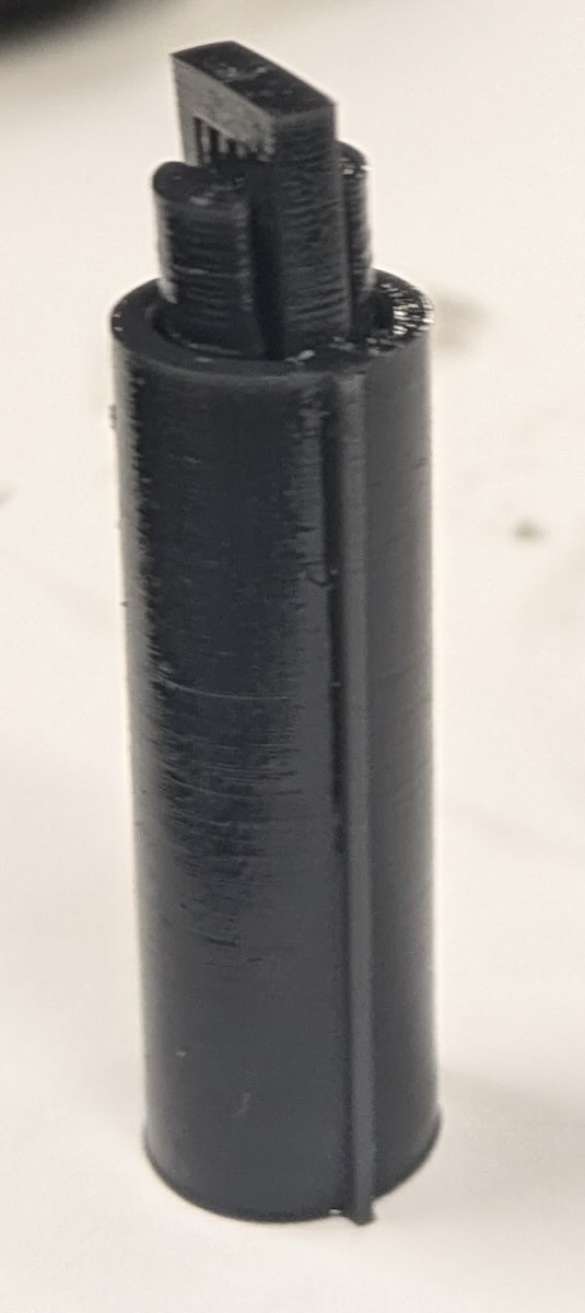
Silicone 40A Resin cylinder printed part

Designing custom tearaway supports

Watch this video for expert tips on designing custom tearaway supports for models printed in Silicone 40A Resin. Learn how to take part geometry into account when creating supports as well as Silicone 40A Resin's unique properties, such as a high elongation at break (230%), and tear strength (12 kN/m). By strategically designing tearaway supports, you can improve print success, ensure easy support removal, and achieve an excellent surface finish with no small touchpoints that could interfere with the part’s application. The video also covers techniques for reinforcing tall parts to enhance printing reliability and demonstrates strategies for common elastomeric models like bellows, gaskets, seals, and tubes.

Models with cups

Include vent or drain holes whenever possible to alleviate suction cups while printing with Silicone 40A Resin. Cupping increases the possibility of print failures resulting from part blowouts. For geometries that don’t have an obvious location for drain holes, consider adding them to custom designed support structures as shown in the example here.

Example model without a custom support structure
Example model with a vent in the custom support structure

Example model without a custom support structure

Example model with a vent in the custom support structure

Design specifications

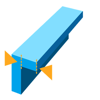
Supported wall thickness
Minimum: 1.0 mm

Supported wall thickness

Unsupported wall thickness
Recommended: 2.0 mm

Unsupported wall thickness

Unsupported overhangs
Maximum length: 400 microns

Unsupported overhangs

Unsupported angles
Recommended: 45 degrees

Unsupported angles

Vertical wire diameter
Recommended: 1.0 mm

Vertical wire diameter

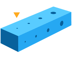
Minimum hole diameter
Recommended: 1.0 mm

Minimum hole diameter

Additional resources