
NOTE:
The guidelines below were developed using Formlabs Grey V4 Resin printing at 100 microns on the Form 4L. You may experience slight variations with other Formlabs resins, different Formlabs printers, and various layer thicknesses.

A successful 3D print starts with a well-designed model. Follow our best practices to optimize designs and reduce failures.
NOTE:
The guidelines below were developed using Formlabs Grey V4 Resin printing at 100 microns on the Form 4L. You may experience slight variations with other Formlabs resins, different Formlabs printers, and various layer thicknesses.
Minimum supported wall thickness

Recommended: 0.2 mm/200 microns
A supported wall is one that is connected to other walls on two or more sides. A supported wall with a thickness of 0.2 mm or less may warp due to the peel forces exerted on the part during the peel process.
Note:
Take care when washing parts with thin walls, which may absorb solvents such as IPA during the washing process. Spending an extended duration in a washing solution can cause deformation of the part, so minimize how long the part is immersed in IPA to limit this effect.
Minimum unsupported wall thickness

Recommended: 0.2 mm/200 microns
An unsupported wall is one that is connected to other walls on fewer than two sides. An unsupported wall with a thickness of 0.2 mm or less may warp or detach from the model during printing.
Note
Take care when washing parts with thin walls, which may absorb solvents such as IPA during the washing process. Spending an extended duration in a washing solution can cause deformation of the part, so minimize how long the part is immersed in IPA to limit this effect.
Maximum unsupported overhang length

Recommended: 5.0 mm/5000 microns
An overhang refers to a part of the model that extends parallel to the build platform. Printing such features without support is discouraged, as layers that cannot maintain their structure often warp or detach. Horizontal overhangs beyond 5 mm do not completely form and become increasingly deformed as the length of the overhang increases. Change the orientation of the model, or click Supports and select Internal Supports in PreForm to ensure overhangs are supported.
Minimum unsupported overhang angle
Recommended: 10° from level
(35 mm long × 10 mm wide × 3 mm thick)
An overhang set at an angle of 10 degrees or less can break off the model during the peel process. Refer to the support article Moving and rotating a model in PreForm to rotate flat surfaces to be more self-supporting.

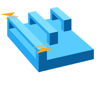
Maximum horizontal support span length
Recommended: 29 mm/29,000 microns
(5 mm width × 3 mm thick)
Span is the distance between two supports. Printing horizontal spans is discouraged, but certain geometries may print successfully. For a 5 mm wide and 3 mm thick beam, spans longer than 29 mm are more likely to fail. Wider beams must be kept shorter to avoid print failures.
Minimum vertical-wire diameter
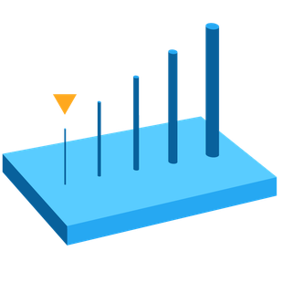
Recommended for a 7 mm-tall wire: 0.3 mm/300 micron diameter
Recommended for a 30 mm-tall wire: 0.6 mm/600 micron diameter
A wire is a feature whose length is at least two times greater than its width. This ratio is key to designing and printing wires. A 0.3 mm thick wire can be up to 7 mm tall before it begins to deform. A wire with a 0.6 mm width has a max height of 30 mm without deformation.
Note: Washing small wires
Take extra care when washing thin wires, as they are weakened by IPA and can easily be damaged. Minimizing how long the part is immersed in IPA limits this effect.
Minimum embossed detail
Recommended: 0.1 mm/100 microns
Embossed details are shallow raised features on the surface of a model like text. Details less than 100 microns thick and 100 microns tall may not be visible on the completed print.

Minimum engraved detail
Recommended: 0.20 mm/200 microns
Engraved details are imprinted or recessed features on the surface of a model. Details recessed less than 200 microns deep or wide may fuse with the rest of the model during the print process.

Minimum clearance
Recommended: 0.4 mm/400 microns
Clearance is the distance between two parts of a model (e.g., the distance between a pair of gears). Parts may fuse if clearance is less than 400 microns.

Minimum hole diameter
Recommended: 0.5 mm/500 microns
Holes with a diameter of less than 500 microns in the X, Y, and Z axes may close during printing.

Minimum drain hole diameter
Recommended: 0.75 mm/750 micron diameter
Drain holes are recommended for resin to escape in models that are a fully enclosed cavity (like a hollow sphere or hollow cylinder printed directly on the build platform). Without drain holes of at least 0.75 mm in diameter, the part may trap resin or air and lead to a cupping blowout failure.

For reference, please see a list of typical dimensional tolerances for features printed in the XY plane on Form 4L generation printers. One test model with various feature sizes 3D was printed on three different printers using Grey Resin V5 and 100 µm layer height, post-cured for five minutes at room temperature.
Comparison between Form 4 and Form 4L
The following table compares the recommended design values or the intended CAD feature size to the measured value of the actual printed feature size found during Formlabs testing. The closer the printed feature size is to the intended CAD feature size, the more precise a printer is. The deviations in the intended CAD feature size and the printed feature sizes are minimal and generally imperceptible to the human eye.
| Form 4L/Form 4BL Grey V5 at 100 microns (Default) | Form 4/Form 4B Grey V5 at 50 microns (Default) | |||
|---|---|---|---|---|
| Intended CAD feature size | Actual printed feature size | Intended CAD feature size | Actual printed feature size | |
| Minimum supported wall thickness | 0.2 mm | 0.3 mm | 0.2 mm | 0.17 mm |
| Minimum unsupported wall thickness | 0.2 mm | 0.3 mm | 0.2 mm | 0.18 mm |
| Maximum unsupported overhang length | 5.0 mm | 5.00 mm | 5.0 mm | 5.00 mm |
| Minimum unsupported overhang angle | 10 deg | 10 deg | 10 deg | 10 deg |
| Maximum horizontal support span length | 29 mm | 29.00 mm | 29 mm | 29.00 mm |
| Minimum vertical wire diameter | 0.3 mm (7 mm tall) 0.6 mm (30 mm tall) | 0.20 mm 0.53 mm | 0.3 mm (7 mm tall) 0.6 mm (30 mm tall) | 0.20 mm 0.59 mm |
| Minimum embossed detail | 0.1 mm | 0.15 mm | 0.1 mm | 0.13 mm |
| Minimum engraved detail | 0.2 mm | 0.2 mm | 0.15 mm | 0.15 mm |
| Minimum clearance | 0.4 mm | 0.26 mm | 0.4 mm | 0.34 mm |
| Minimum hole diameter | 0.5mm | 0.52 mm | 0.5 mm | 0.42 mm |
| Minimum drain hole diameter | 0.75 mm | 0.95 mm | 0.75 mm | 0.91 mm |