
Required Supplies:
Formlabs:
- T20 Torx driver (provided with the Fuse Blast)
- 7 mm nut driver or box wrench (provided with the Fuse Blast)
Third-party:
- Small flat-blade screwdriver
- 2-pin jumper (0.1 in / 2.54 mm pitch)

The Fuse Blast has Wi-Fi functionality for receiving firmware updates and uploading log files. Wi-Fi can be turned off via the machine’s touchscreen, but depending on your organization's security requirements, you may need to physically disable the Wi-Fi hardware before using the machine.
Use this guide to disable Wi-Fi hardware on the Fuse Blast.
Required Supplies:
Formlabs:
Third-party:
Estimated time: 20–30 minutes
Danger:
Read and follow all safety instructions and warnings in the operator manual. Replacement with incorrect parts can lead to burns, shock, fire, or explosion. Dispose of all parts in accordance with local regulations.
Preparing the workspace
Overview: Prepare the Fuse Blast and a clean workspace for disabling the Wi-Fi hardware.
Step 1: Prepare the workspace
Clear a workspace. Ensure that the workspace is well-ventilated, level, and clean.
Step 2: Unplug the machine
Disconnect the power cable from the machine before continuing with maintenance. Do not perform maintenance on the machine while it is connected to power. Wait five minutes after disconnecting the printer from power before proceeding.
Danger:
Performing this procedure on the Fuse Blast while it is plugged in increases the risk of electric shock. Never remove any external paneling while the Fuse Blast is plugged in. Never reconnect the Fuse Blast to power while the external paneling is uninstalled.
Removing the upper sidecar panel
Overview: Uninstall the upper sidecar panel to access the motherboard.
Notice:
The Fuse Blast contains sensitive electronic components. Ground yourself before touching any electronics in the machine by using an antistatic wrist band or touching a grounded piece of metal.
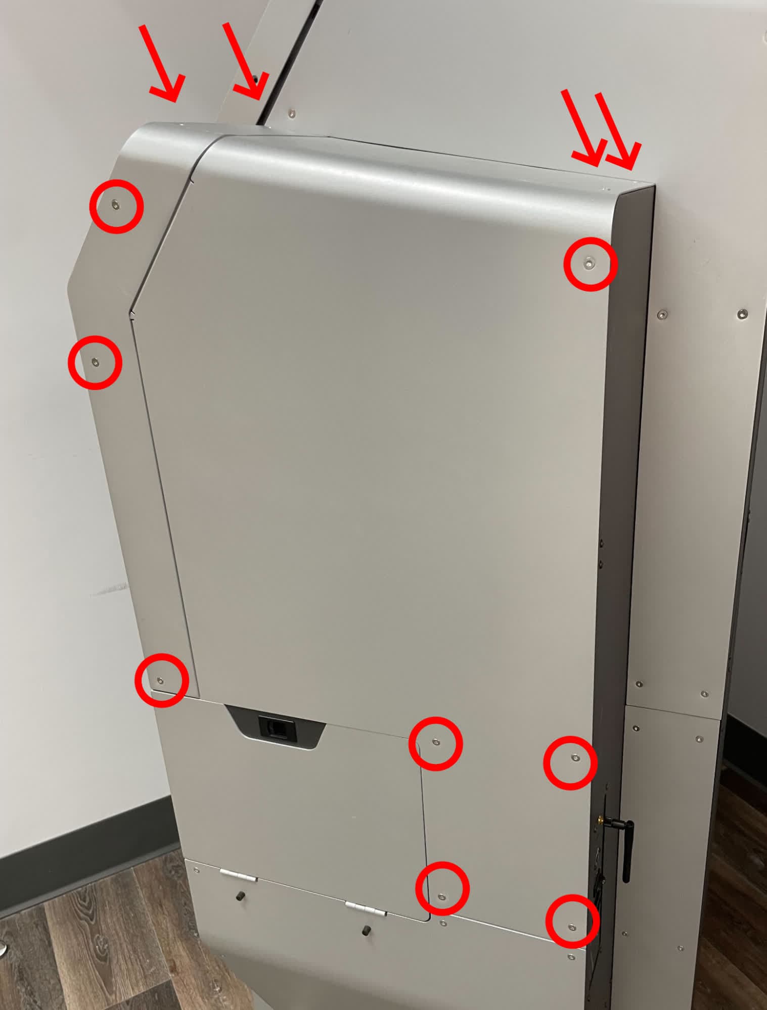
The air metering valve is located in the sidecar on the right side of the machine. Using a T20 Torx driver, loosen and remove the 12 T20 Torx screws securing the upper sidecar panel to the Fuse Blast. Set the screws aside.
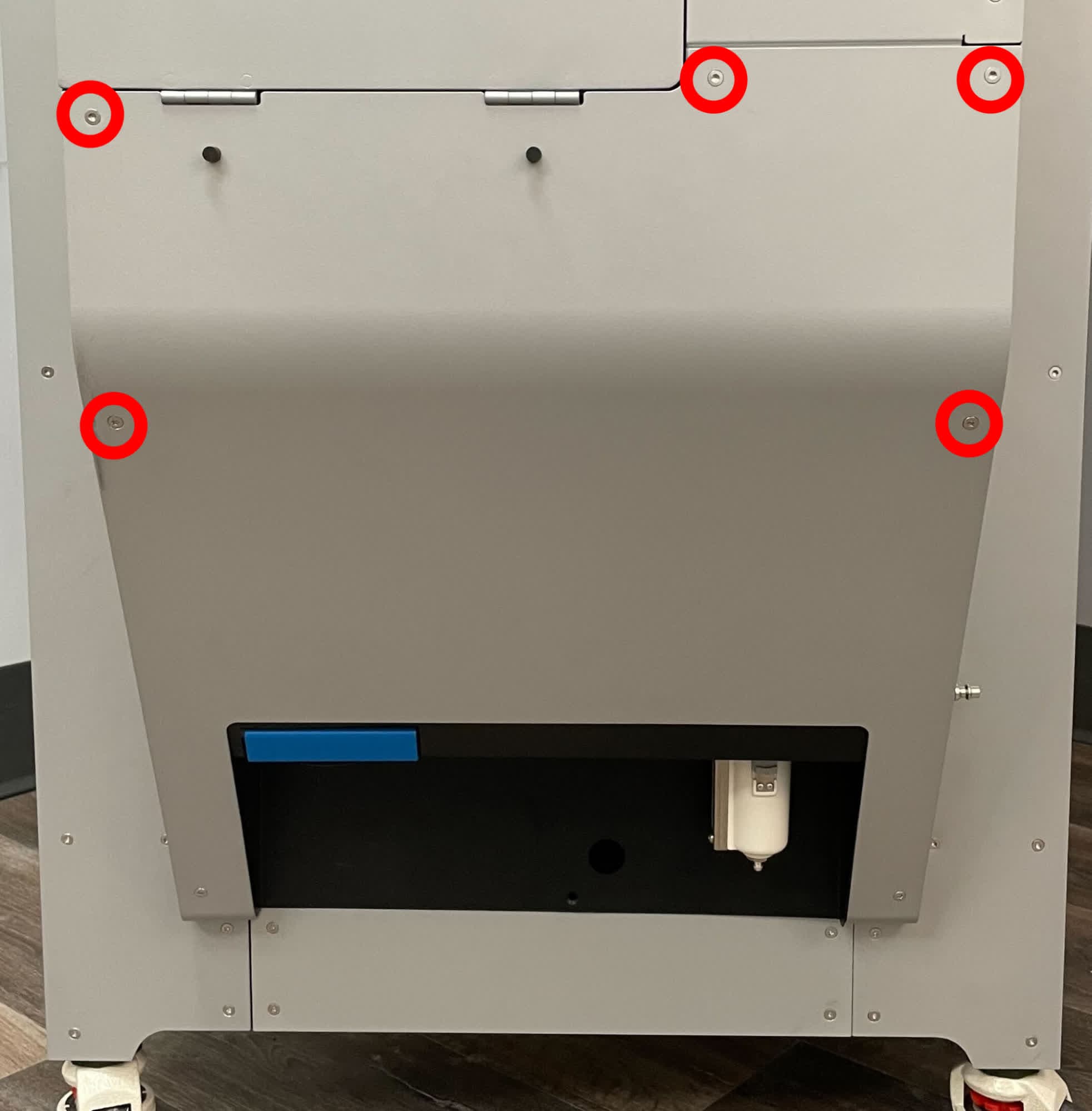
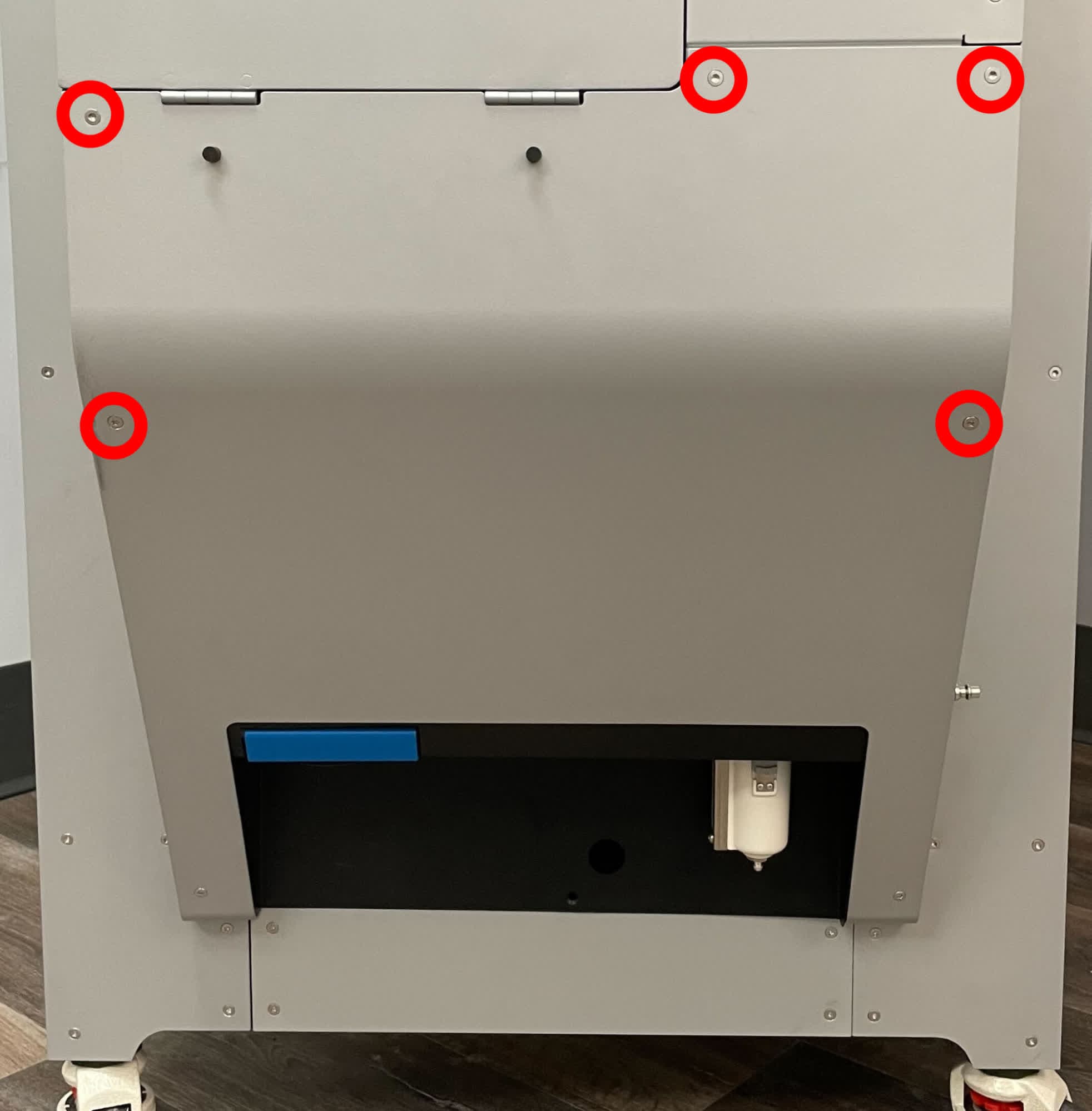
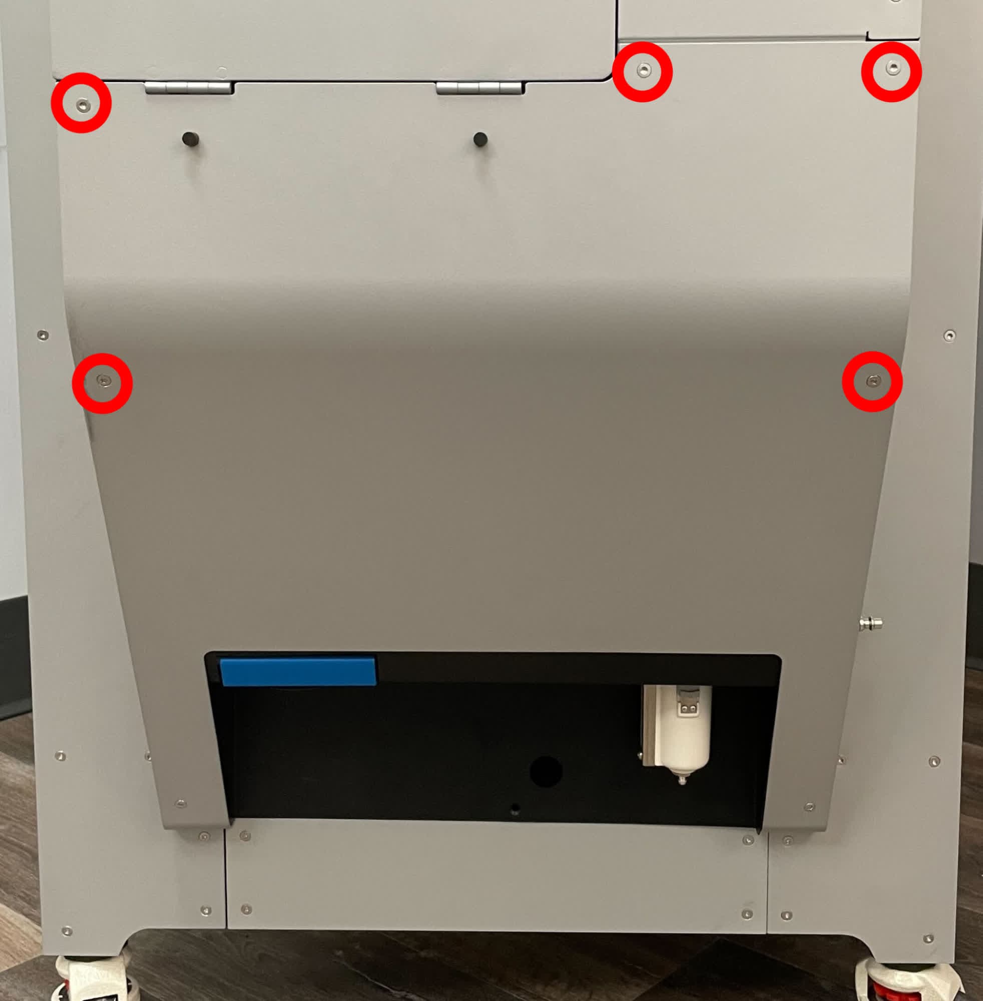
The lower sidecar panel must be moved slightly to free the upper sidecar panel. Using a T20 Torx driver, loosen and remove the five T20 Torx screws shown above. Set the screws aside. Do not remove the two screws at the bottom of the lower sidecar panel.
Step 3: Remove the upper sidecar panel
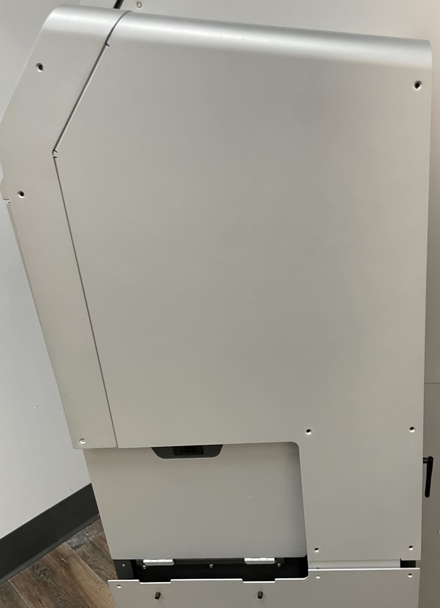
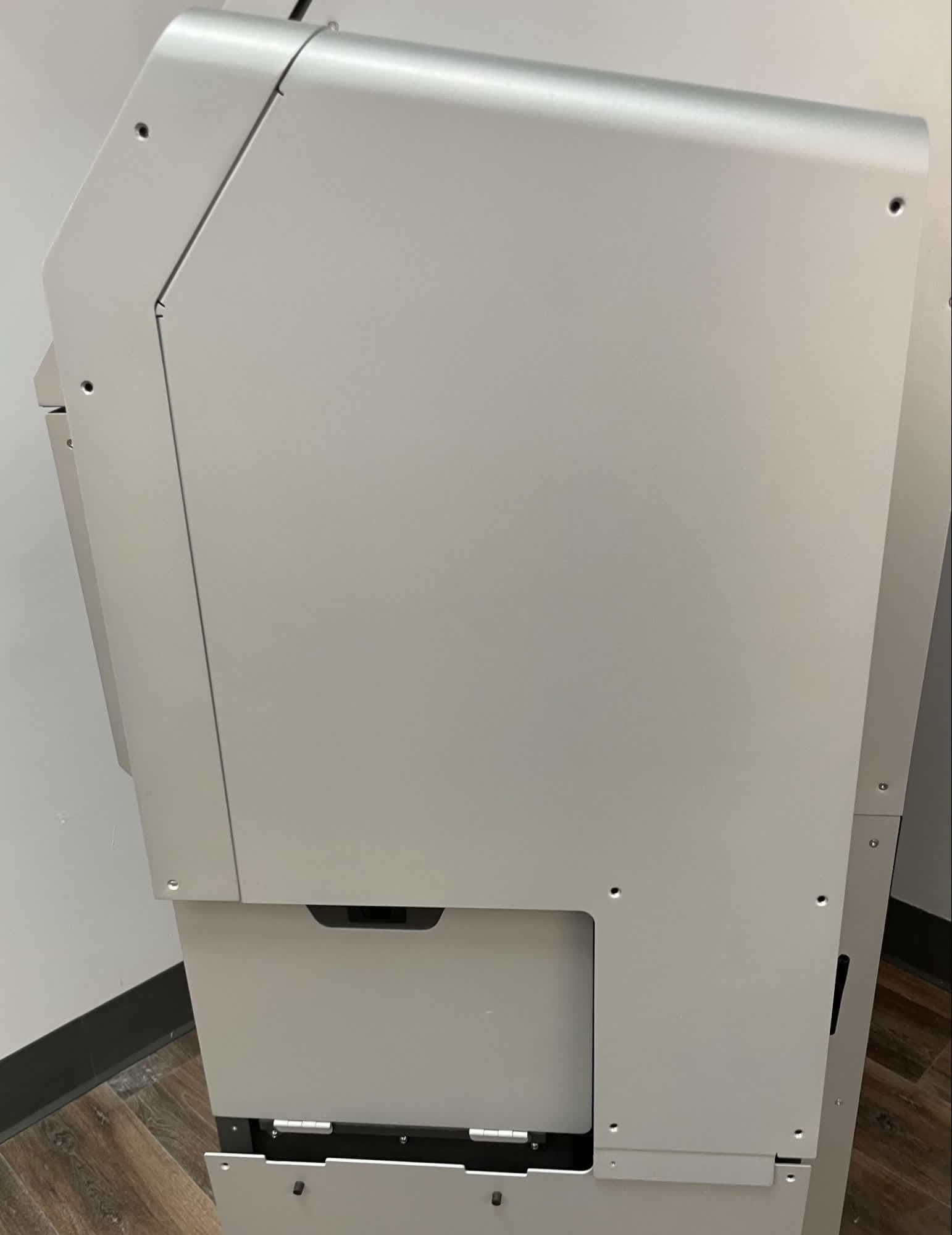
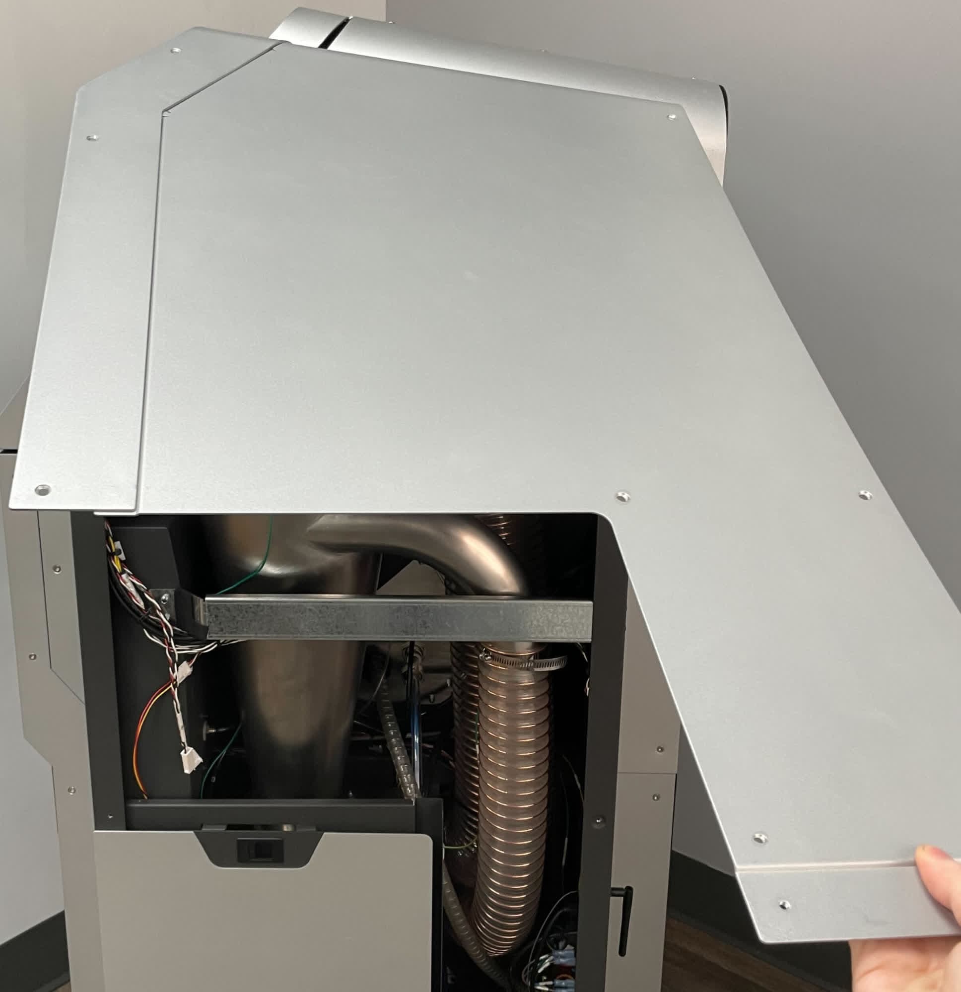
Untuck the bottom of the upper sidebar panel from behind the lower sidecar panel. Rotate the panel upwards until it is horizontal. Once it is horizontal, pull forward to disengage it. Set the upper sidecar panel aside.
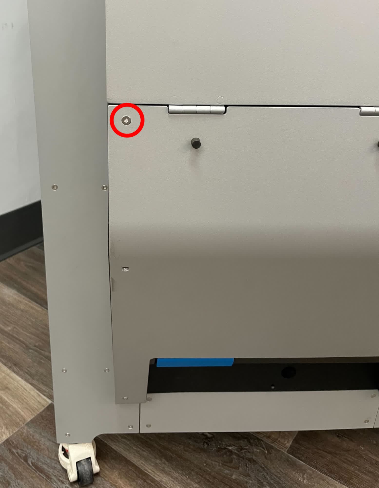
Thread at least one of the lower sidecar panel retention screws back into the lower sidecar panel to avoid inadvertently bending it.
Removing the cyclone separator outlet hose
Overview: Disconnect and remove the cyclone separator outlet hose to access the electronics box and motherboard.
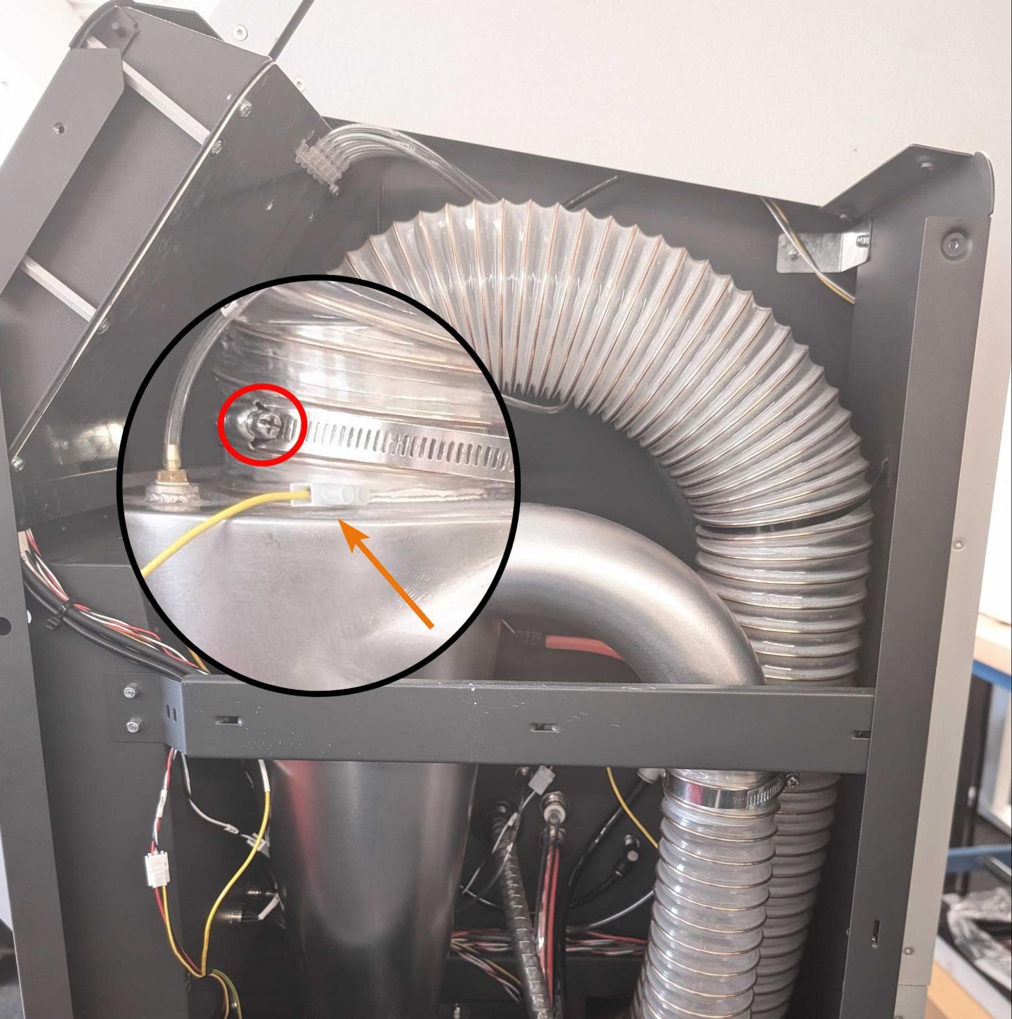
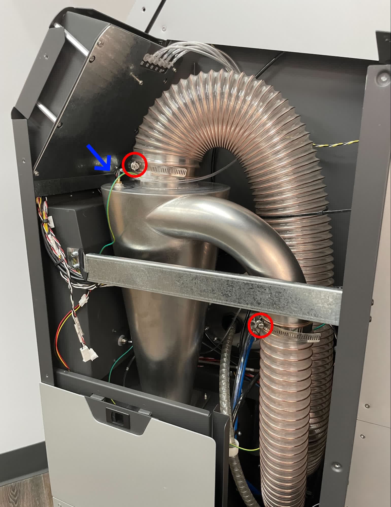
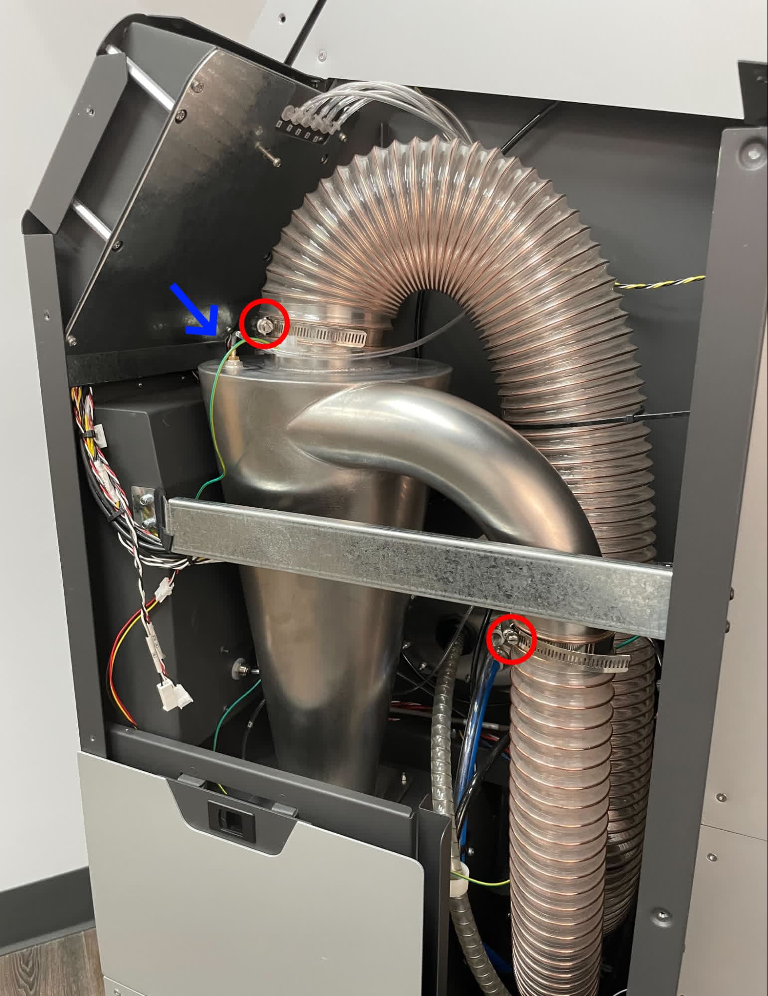
Using a small flat-blade screwdriver, loosen the hose clamp from the top of the cyclone separator. Gently lift the tubing off of the cyclone separator and drape it to the side. Be careful not to break the grounding connection to the tubing.
Continue to Disabling the Wi-Fi hardware . If you find it difficult to to open the electronics box and access the motherboard, return here and remove the entire cyclone separator.
Removing the cyclone separator (optional)
Overview: Disconnect and remove the cyclone separator to more easily access the electronics box and motherboard.
Using a small flat-blade screwdriver, loosen the hose clamps from the cyclone separator. Pull the pressure tap hose off of the cyclone separator. The pressure tap is located close to the front of the machine. If the pressure tap tube is difficult to remove or has deformed from use, it can be cut at the barbed fitting with a utility knife.
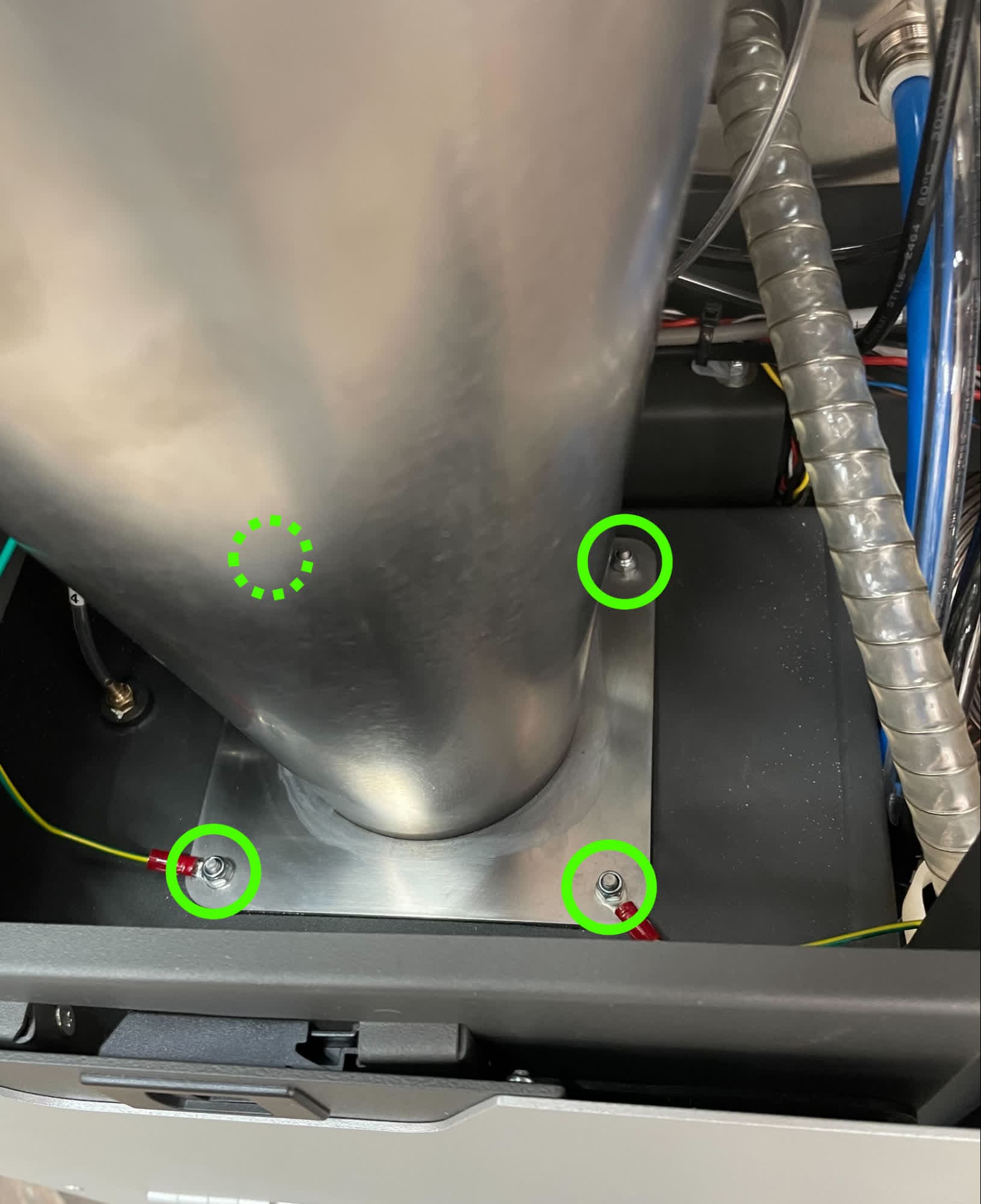
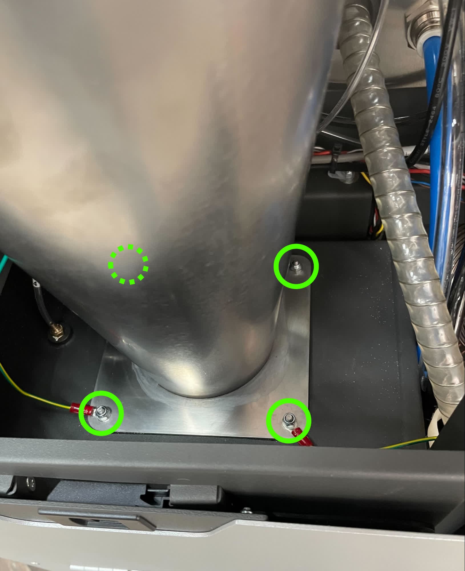
Using a 7 mm nut driver or box wrench, loosen and remove the four hex nuts securing the cyclone separator to the Fuse Blast. Set the nuts aside. Move the two grounding wires out of the way of the cyclone separator.
Remove the cyclone separator and the gasket below it from the machine. Set them aside on a clean surface.
Disabling the Wi-Fi hardware
Overview: Access the motherboard and disable the Wi-Fi hardware.
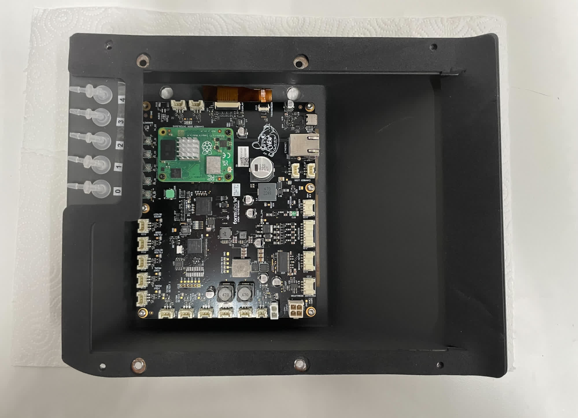
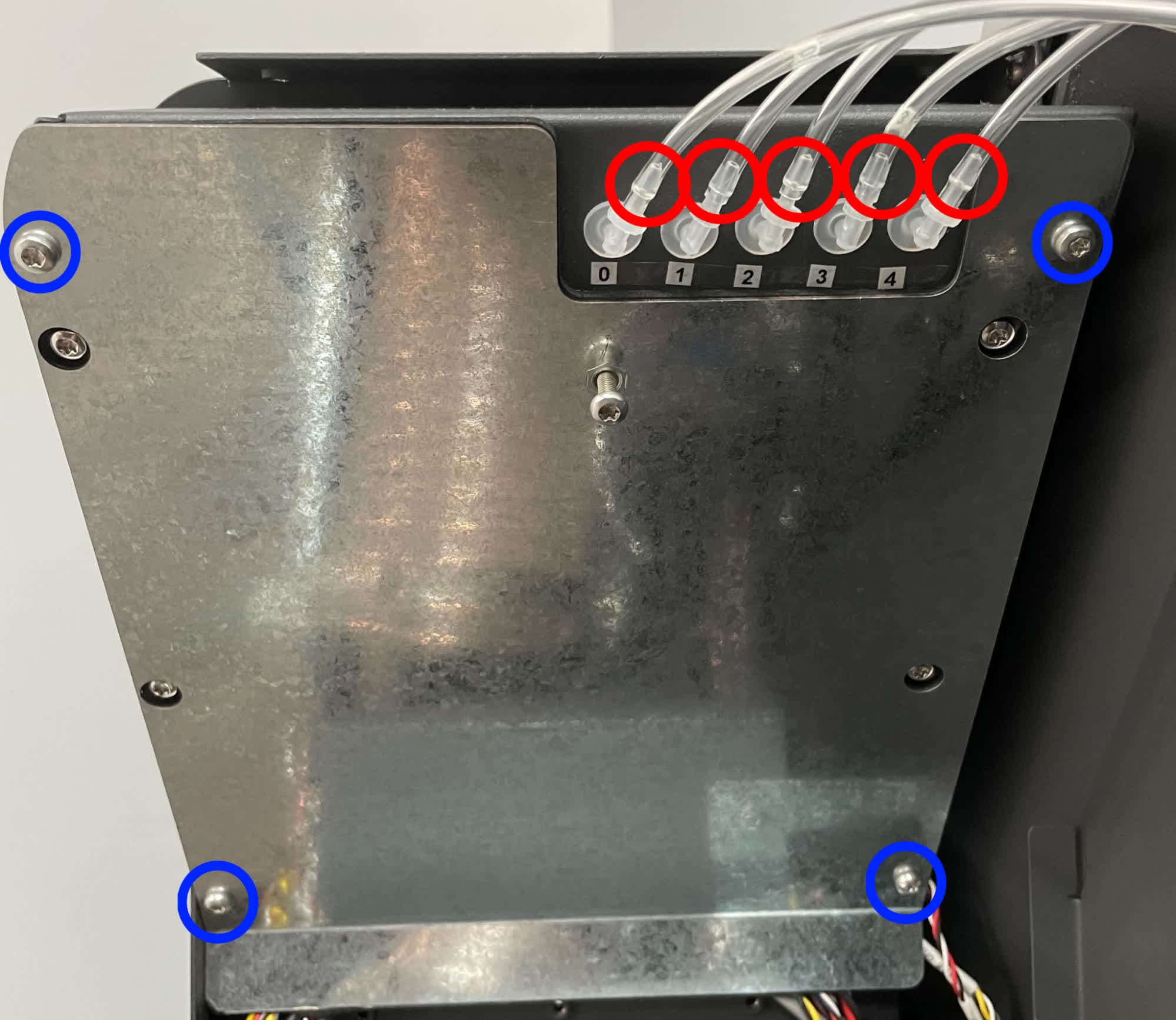
Using a T20 Torx driver, loosen and remove the four T20 Torx screws securing the electronics box cover to the machine. Set the screws and the cover aside. Take care not to damage the five pressure tap tubes connected to the electronics box.
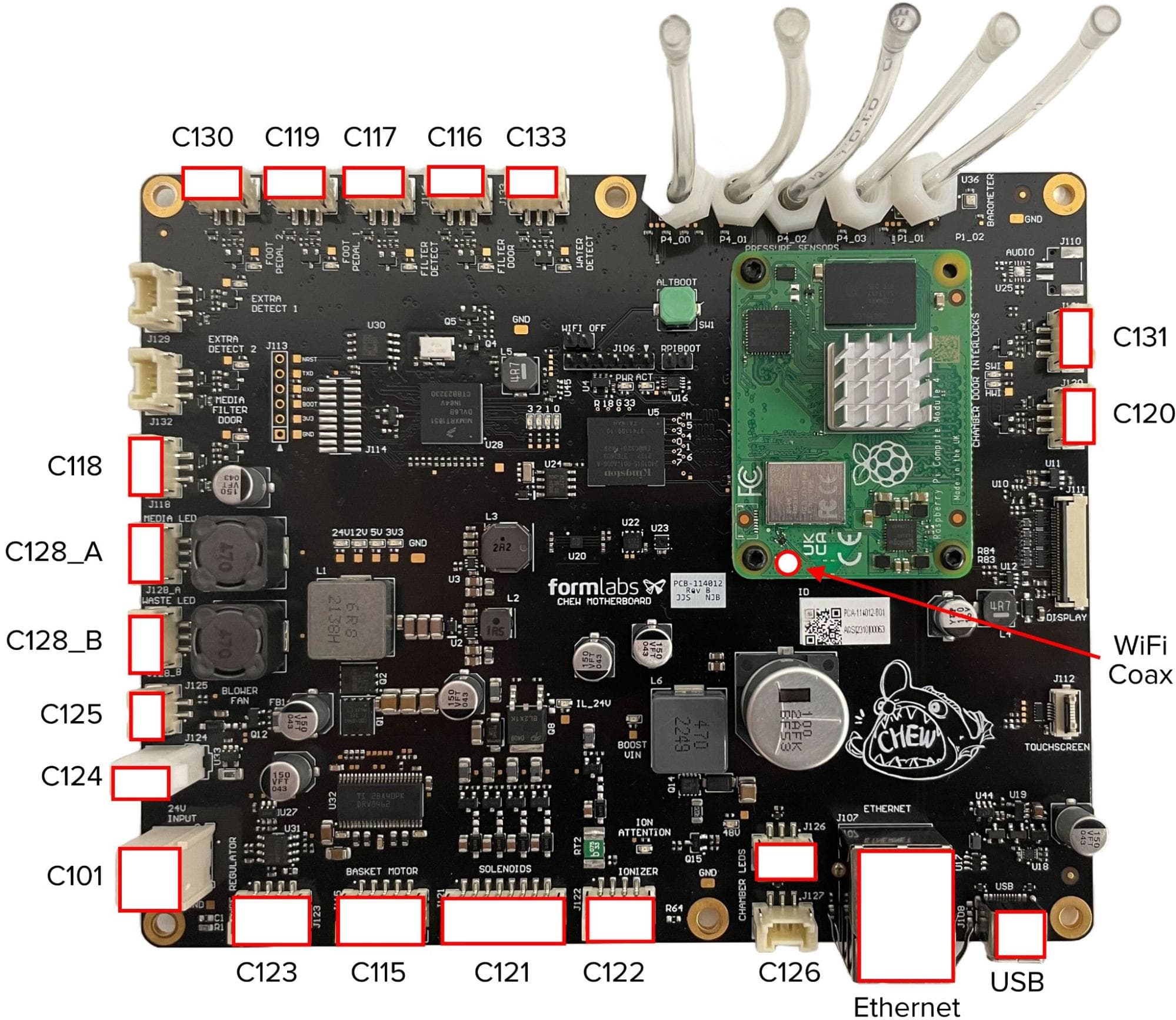
The Fuse Blast motherboard has a header labeled Wi-Fi OFF, located near the top of the board. Place a 2-pin jumper (0.1 in / 2.54 mm pitch) on the header to disable Wi-Fi on the machine.
Place the electronics box cover back on the electronics box, taking care not to pinch or damage the pressure tap tubes. Thread one T20 Torx screw into each of the four screw holes in the corners of the electronics box cover. Use a T20 Torx driver to tighten until snug.
Reinstalling the cyclone separator (optional)
Overview: If you previously uninstalled the entire cyclone separator to access the electronics box, reinstall and secure the cyclone separator.
Place the cycle separator gasket on the cyclone separator mount, aligning the holes in the corners of the gasket with the threaded posts.
Place the cycle separator on the gasket, aligning the holes in the corners of the cyclone separator base with the threaded posts.
Mount the two grounding wires on two of the cyclone separator posts. Thread one 7 mm nut onto each of the posts. Use a 7 mm nut driver or box wrench to tighten the nuts until they are secure but the gasket is not fully compressed.
Press the cyclone pressure tap tube (labeled 0) onto the tap at the top of the cyclone separator. Reinstall the air/media outlet hose and the cyclone outlet hose to the cyclone separator. Tighten the hose clamps using a 6.5 mm slotted screwdriver.
Reconnecting the cyclone separator outlet hose
Overview: After closing the electronics box, reinstall and secure the cyclone separator.
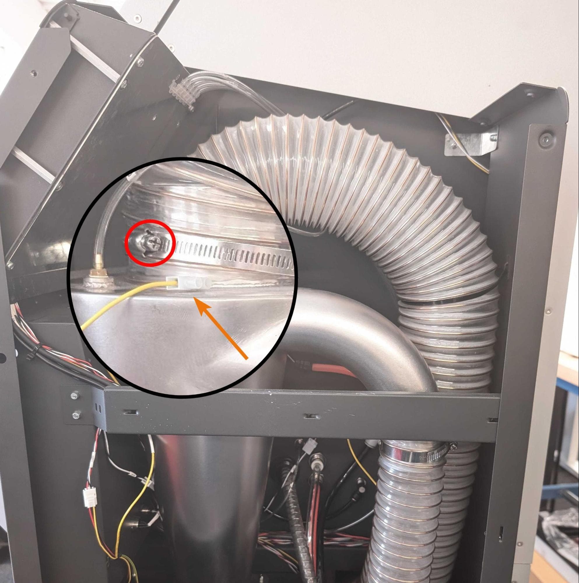
Slip the cyclone outlet hose onto the top of the cyclone separator. Tighten the hose clamp using a 6.5 mm slotted screwdriver.
Reinstalling the upper sidecar panel
Overview: Reinstall and secure the upper sidecar panel.
Use a T20 Torx driver to loosen and remove any lower sidecar panel retention screws you previously reinstalled. Set the screws aside. Do not remove the two screws at the bottom of the lower sidecar panel.
Step 2: Mount the upper sidecar panel
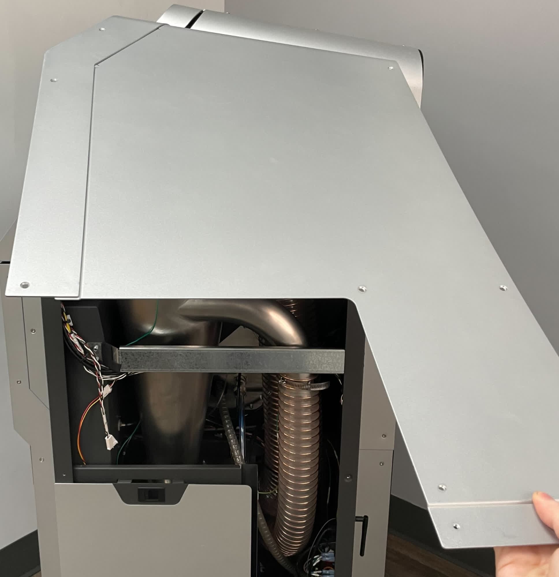
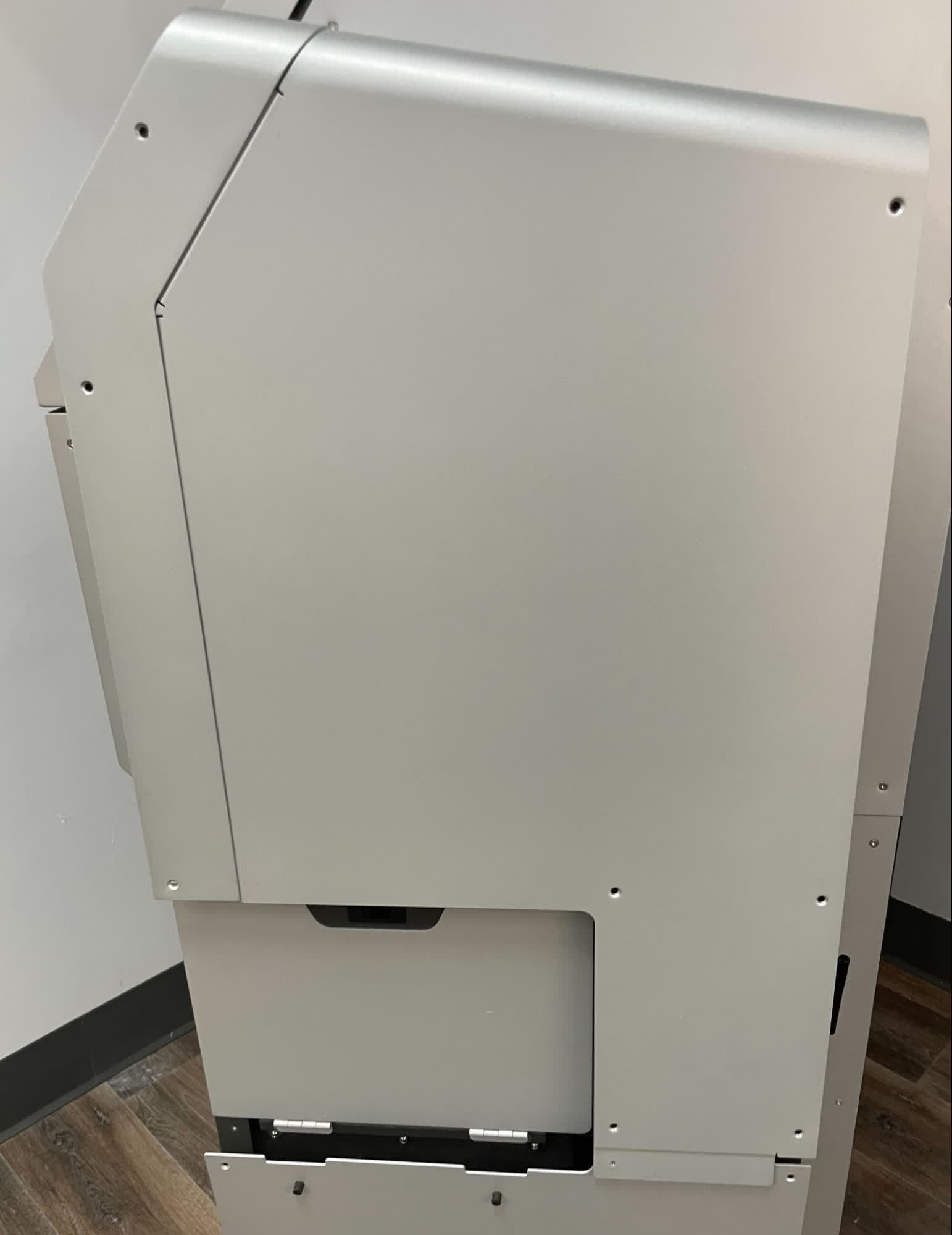
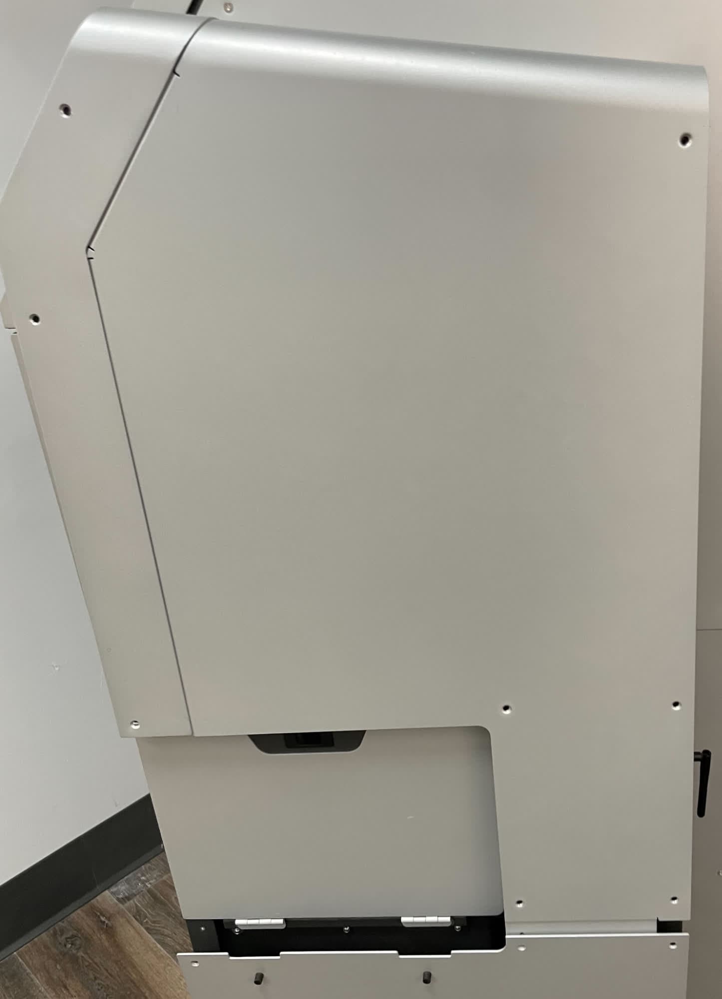
Insert the upper sidecar panel horizontally such that the flange tucks under the upper panel. Rotate the sidecar panel downward, then tuck the lower flange under the lower sidecar panel.
Thread one upper sidecar panel retention screw into each of the 12 screw holes in the upper sidecar panel. Use a T20 Torx driver to tighten until snug.
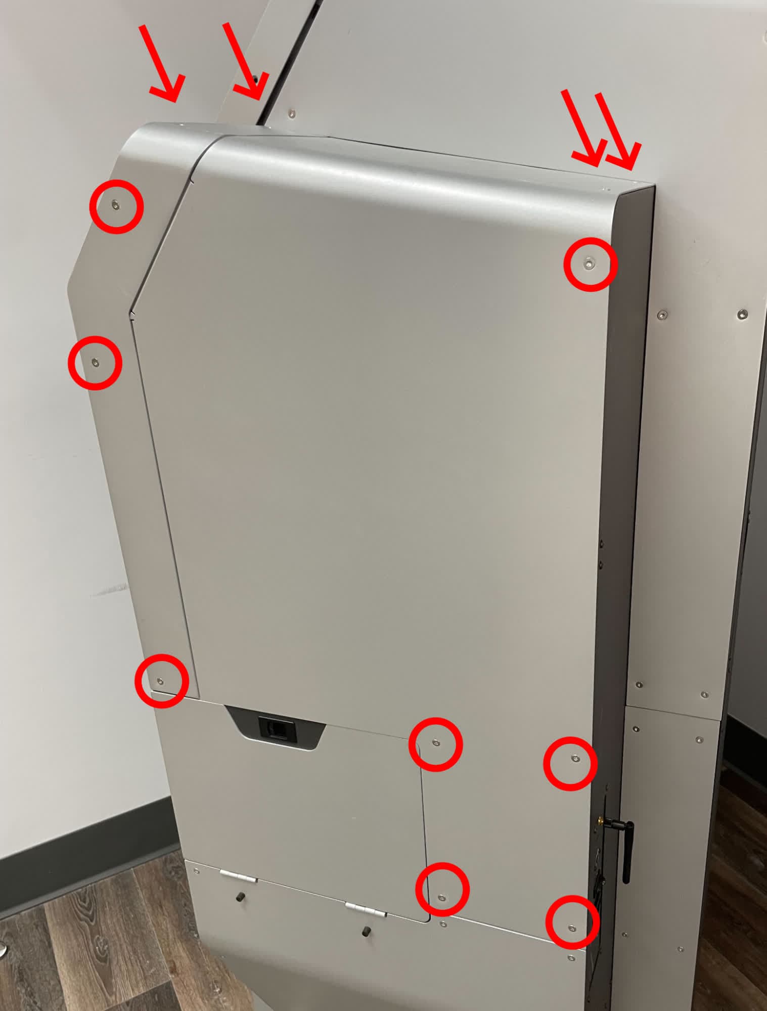
Thread one upper sidecar panel retention screw into each of the five open screw holes in the lower sidecar panel. Use a T20 Torx driver to tighten until snug.
Finalizing the procedure
Overview: After disabling the Wi-Fi hardware, power on the machine and perform final checks.
Step 1: Power on the machine
Connect the power cable to the machine and the power supply. Flip the power switch on the back of the machine to the ON position. The machine initializes. Test the machine to ensure that it operates normally (with the exception of Wi-Fi connectivity).