WHITE PAPER
Formlabs Logo

Replacing a Fuse 1 generation flipper motor assembly

Replacing a Fuse 1 generation flipper motor assembly

The two flipper motor assemblies in a Fuse 1 generation printer help handle unsintered powder and move it into the path of the recoater. A faulty or malfunctioning flipper motor assembly will prevent the printer from working normally.

Use this guide to replace either flipper motor assembly in a Fuse 1 generation printer.

Fuse 1 generation flipper motor

Required supplies:

Formlabs:

Third-party:

  • 2 mm hex driver (flat-end)
  • 2.5 mm hex driver (flat-end)
  • 3 mm hex driver (flat-end)
  • 6.5 mm slotted screwdriver
  • Flipper calibration tool, 1-inch parallel gauge tool, or other similar flat, rigid object
  • Safety glasses
  • Nitrile gloves
Estimated time: 30–45 minutes

Danger:

Read and follow all safety instructions and warnings in the operator manual. Replacement with incorrect parts can lead to burns, shock, fire, or explosion. Dispose of all parts in accordance with local regulations.

Warning:

Do not perform this procedure if the printer was printing less than six hours prior. Failure to do so may result in serious burns. Allow the print enclosure to cool to room temperature before touching or inspecting any Fuse 1 components.

Cleaning the flipper trough

Overview: Prepare the printer for the repair and clean the powder trough corresponding to the flipper being serviced.

Step 1: Prepare the workspace

Clear a workspace around your printer. Ensure that the workspace is well-ventilated and free of dust. Put on appropriate personal protective equipment for the powder in the printer, based on the safety data sheet for the powder.

Disconnect the Wi-Fi antenna and nitrogen source (Fuse 1+ 30W only).

Step 2: Open the print enclosure door

Open the print enclosure door using the touchscreen. If there is a build chamber inserted, unplug and remove it.

Step 3: Remove the spatial filter retention screw

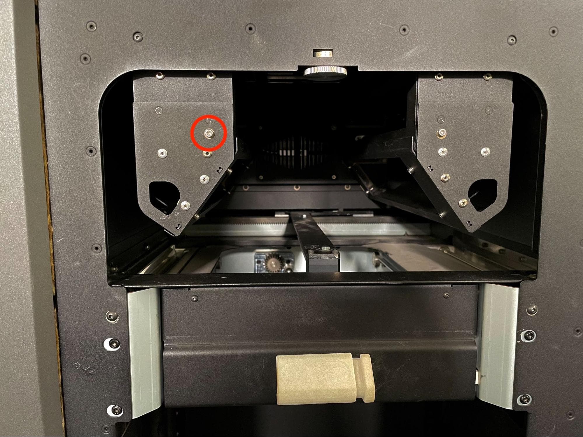
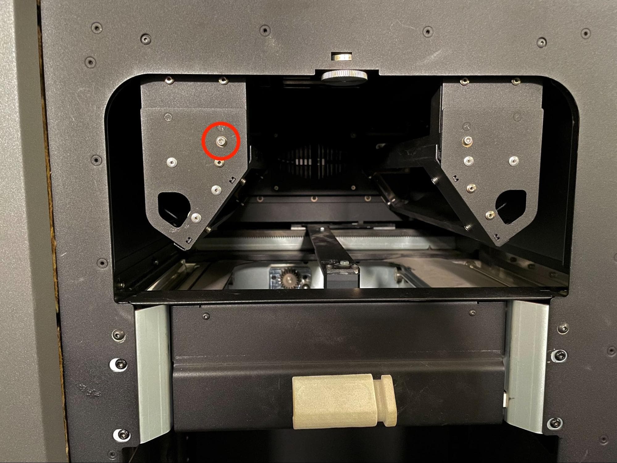
Locate the side of the printer corresponding to the flipper motor being replaced. The quartz tube heater spatial filter needs to be removed on that side to clean the powder trough. The other filter does not need to be removed

Use a 2.5 mm hex driver to remove the 8.0 mm M3 cap screw holding the quartz tube heater’s spatial filter to the frame.

Remove the heater filters

Step 4: Remove the spatial filter

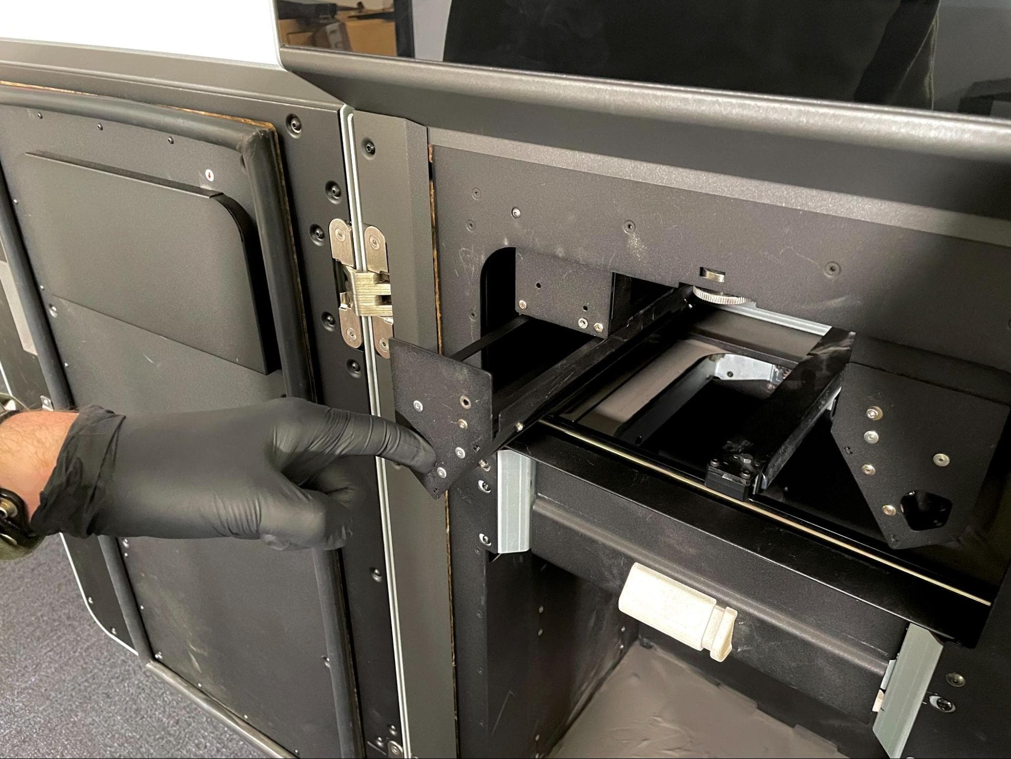
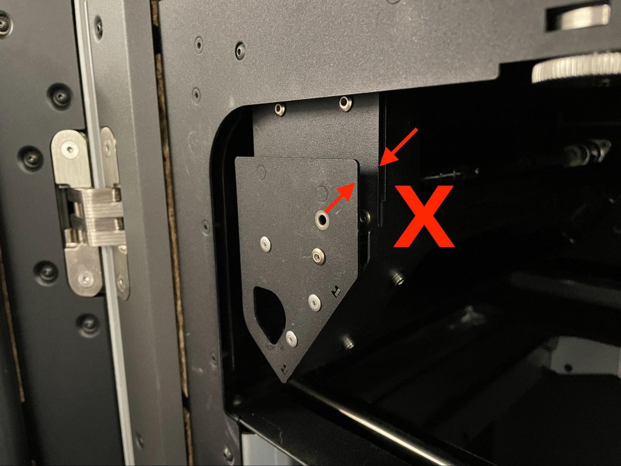
Insert your finger into the slot on the spatial filter and pull it away from the printer to remove it from the print enclosure. Set the spatial filter aside.

Remove the heater filters

Step 5: Move the recoater roller

On the touchscreen, navigate to Maintenance > Move Motors. The Motor Moves screen appears. Touch and hold the appropriate directional toggle that will move the recoater to the opposie side of the printer from the flipper being serviced.

Caution:

Crush hazard. Keep your hands, clothing, and tools clear of the path of the recoater roller while it is moving.

Step 6: Move the flipper

In the Motor Moves window, rotate the flipper to be serviced using the Flipper (Left) or Flipper (Right) controls until it is pointing straight up.

Step 7: Clean the powder trough

Vacuum out all powder from the vicinity of the flipper and its trough. If needed, use the controls in the Motor Moves window to rotate the flipper and move powder out of the bottom of the trough.

Step 8: Turn off the printer

Power off the printer using the switch at the back of the printer, then disconnect it from its power source. Wait at least five minutes before continuing.

Notice:

Replacing a motor while the printer is powered on can damage the motor and temperature controller board.

Removing the rear panels

Overview: Remove the rear panels to access the interior of the printer.

Step 1: Remove the lower rear panel screws

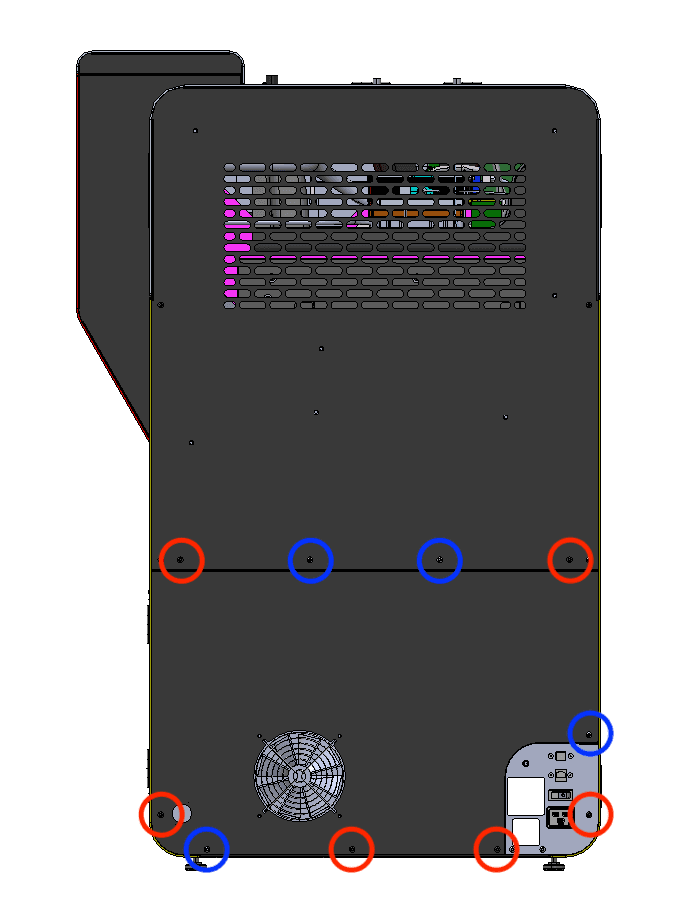
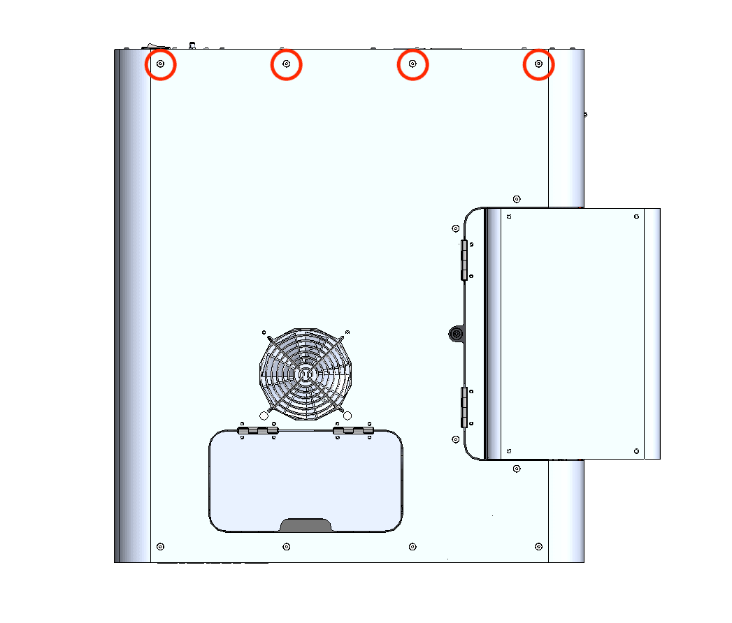
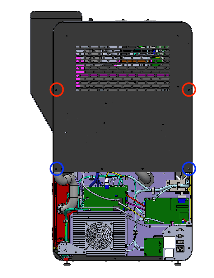
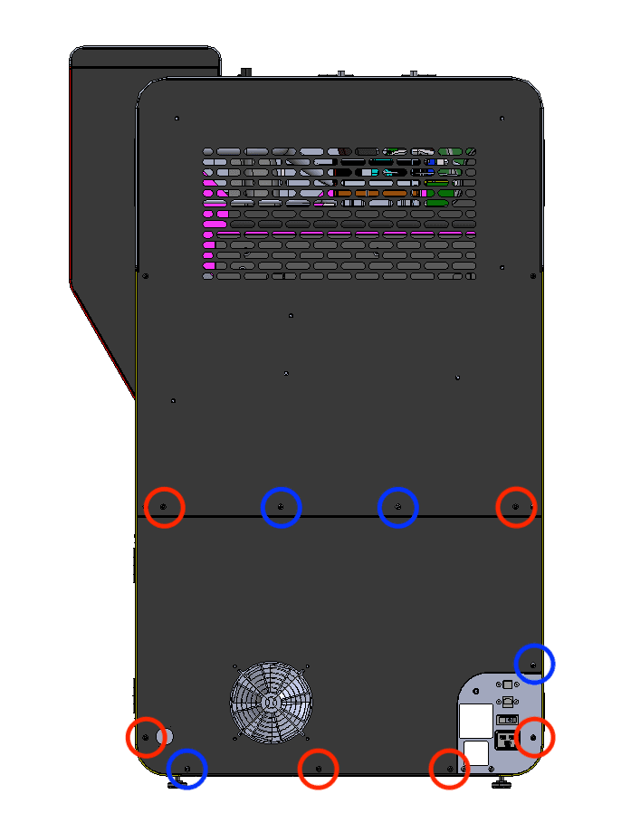
The six black lower rear panel screws are circled in red. The four chrome lower rear panel grounding screws are circled in blue.

Using a 2.5 mm hex driver, remove the six black panel screws and the four chrome panel grounding screws securing the lower rear panel to the printer. Set the screws aside, taking care to separate the black and chrome screws for later reinstallation.

Step 2: Remove the lower rear panel from the printer

Pull the lower rear panel straight back and away from the printer. Lay it down on a flat, clean surface.

Step 1: Remove the lower rear panel screws

Step 3: Locate the exhaust duct and ring clamp

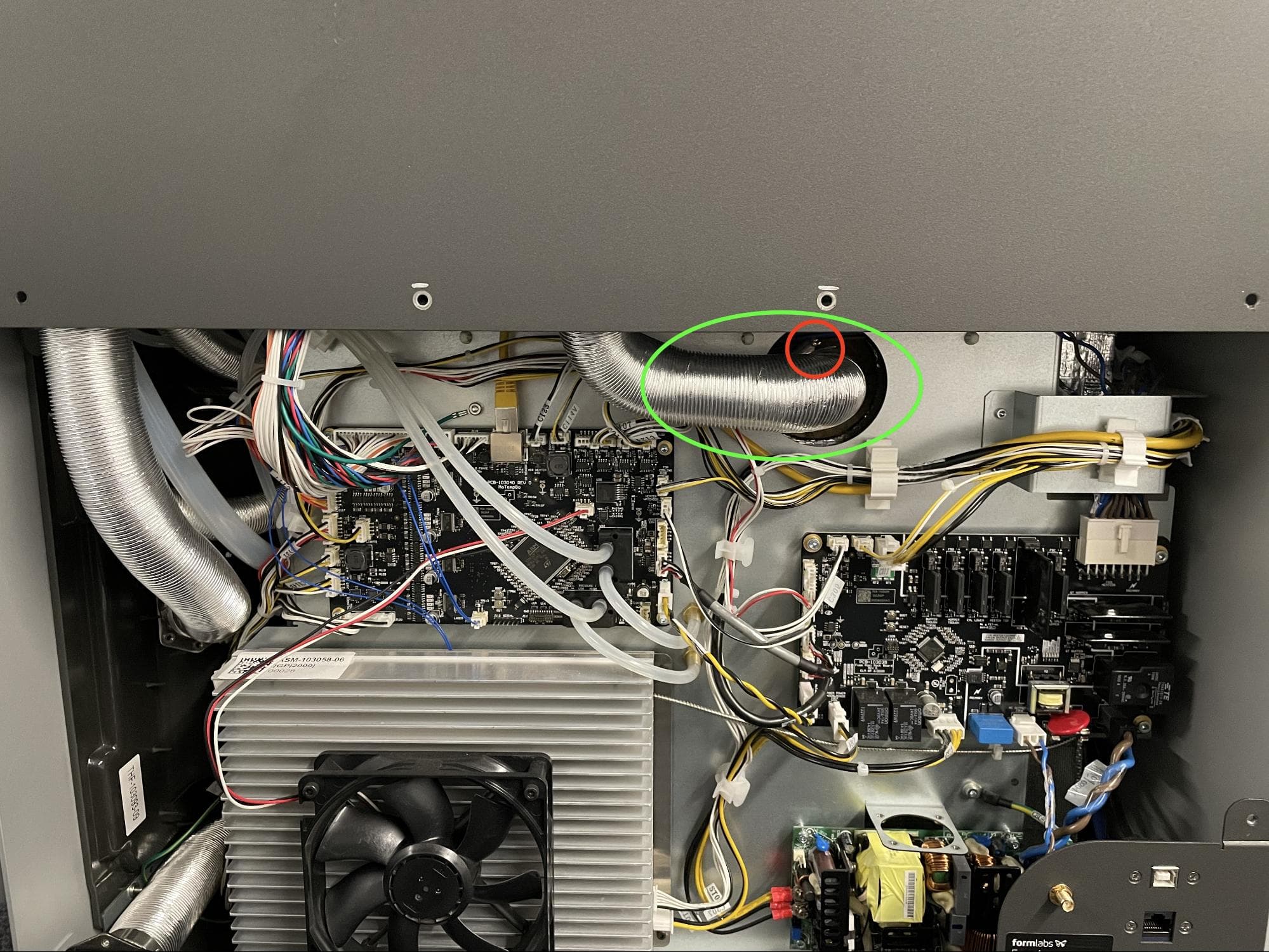
Locate the ring clamp attached to the exhaust duct in the center of the printer.

Step 4: Loosen the ring clamp screw

Using a 6.5 mm flathead screwdriver, loosen the ring clamp screw. Do not remove the screw. Pull the exhaust duct away from the exhaust pipe.

Step 3: Locate the exhaust duct and ring clamp

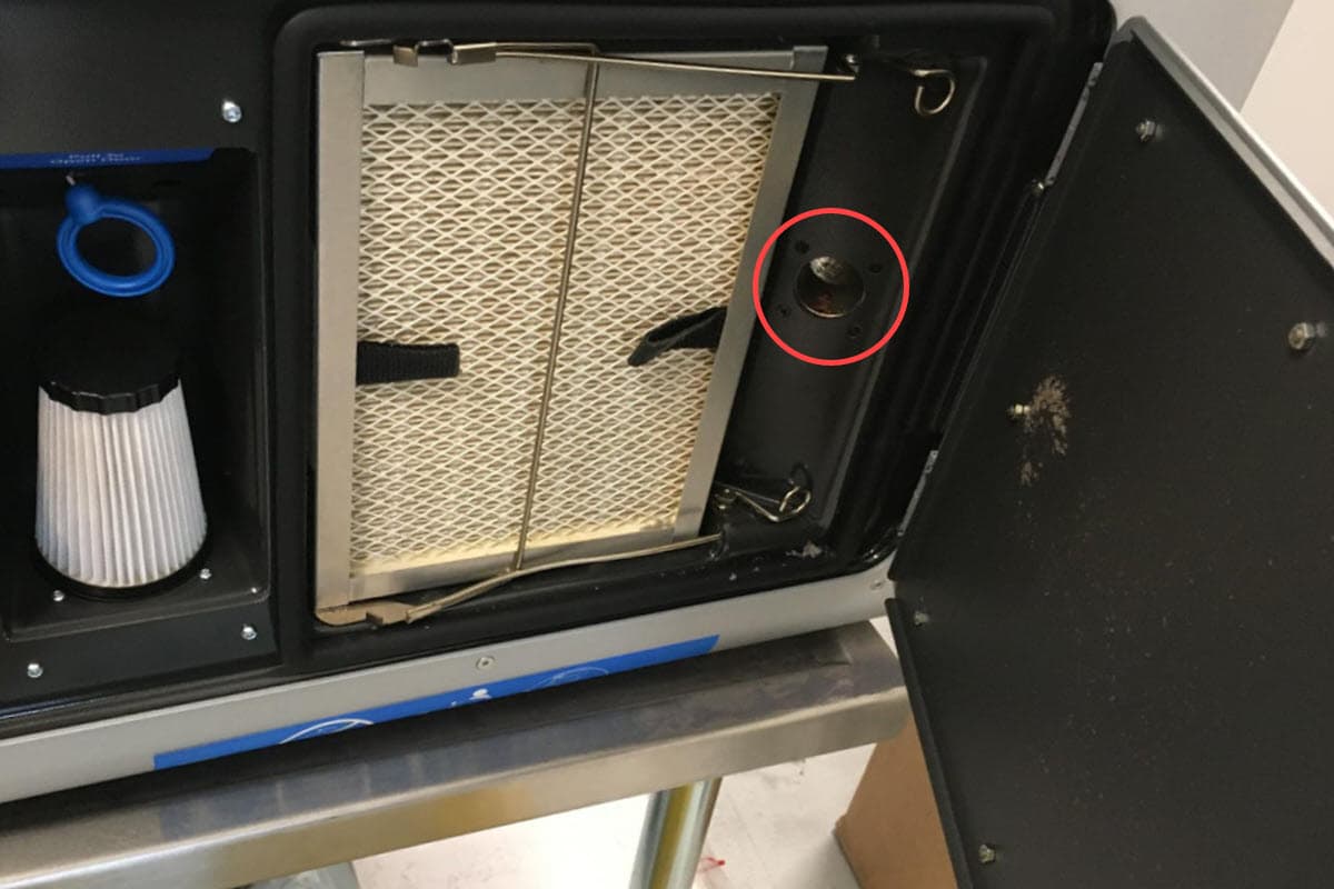
Step 5: Locate the exhaust inlet

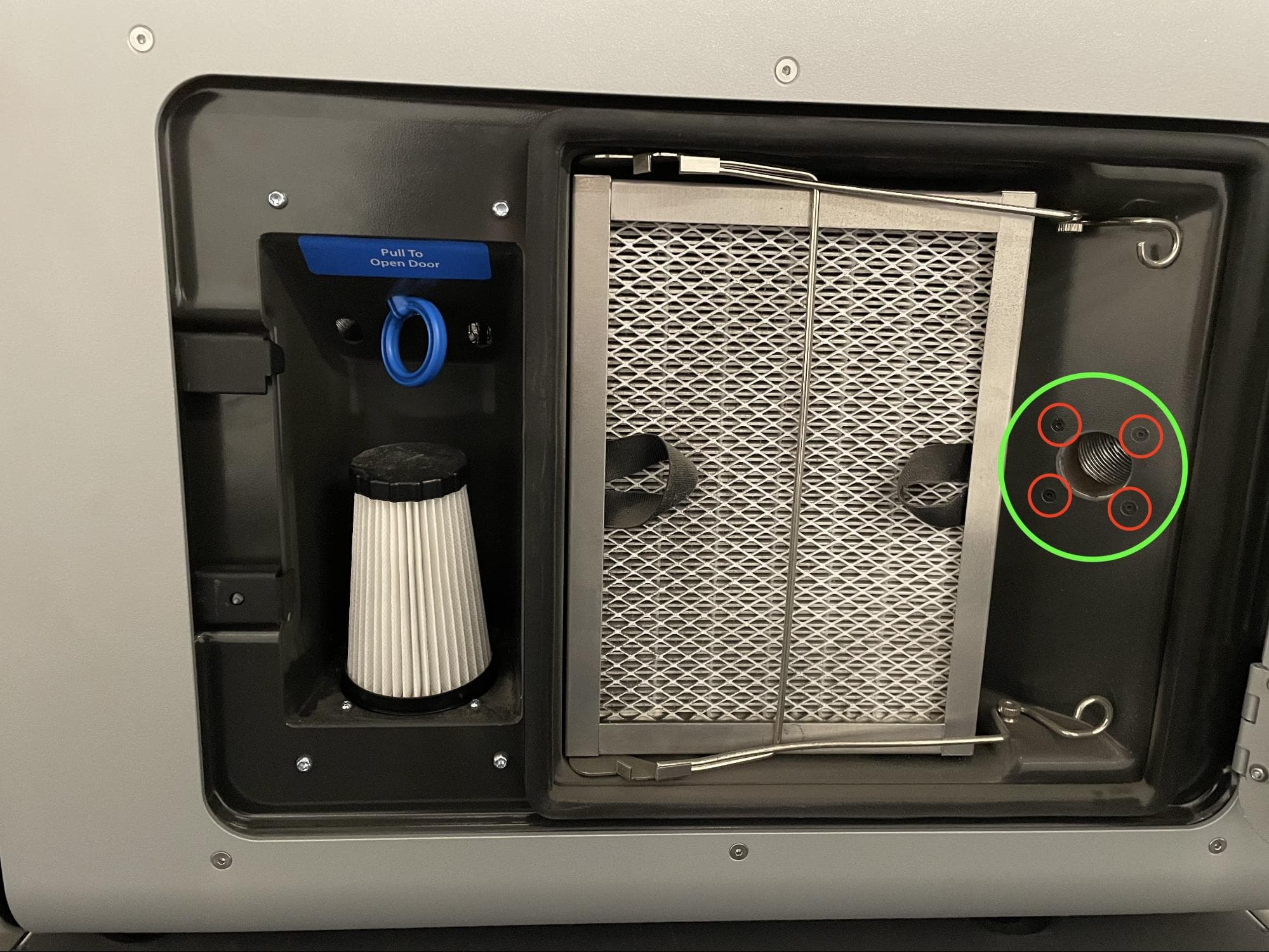
Open the filter cabinet door on the printer. Locate the exhaust inlet on the right side of the cabinet.

Step 5: Locate the exhaust inlet

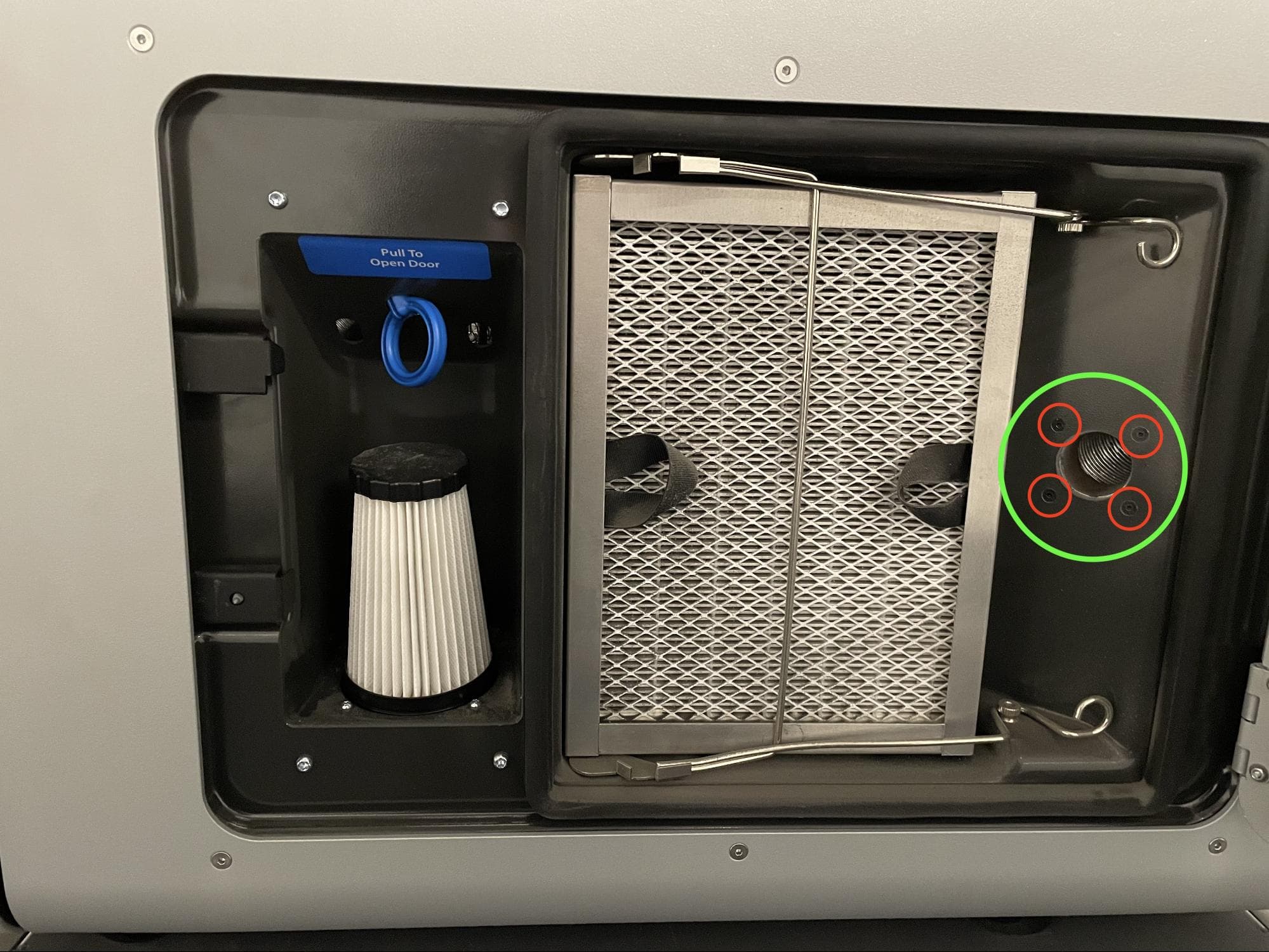
Step 6: Remove the exhaust inlet screws

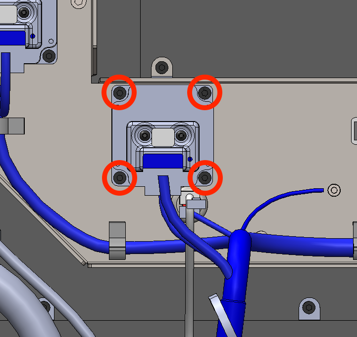
Using a 2.0 mm hex driver, remove the four screws attaching the exhaust inlet to the filter cabinet. Set the screws aside.

Step 6: Remove the exhaust inlet screws

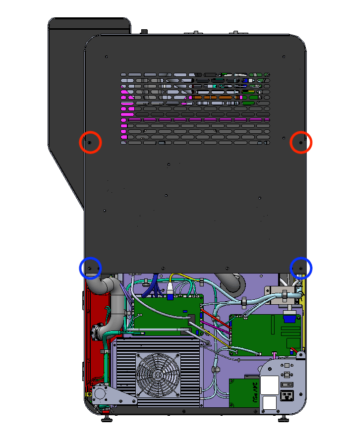
Step 7: Remove the upper rear panel screws

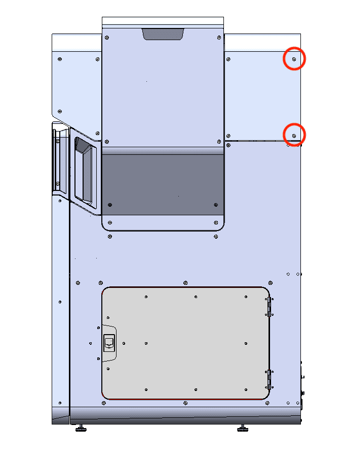
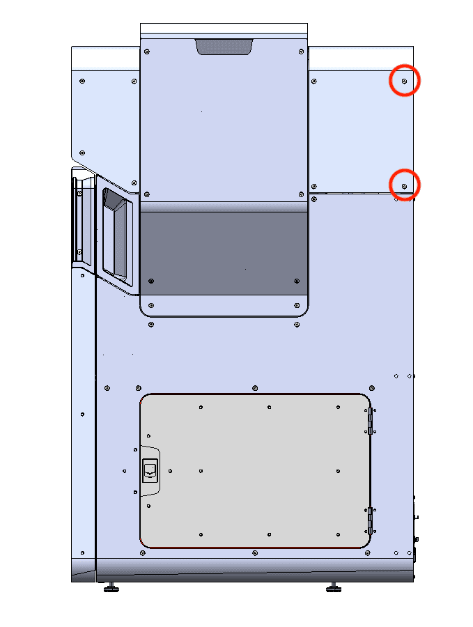
The two black upper rear panel screws are circled in red. The two chrome upper rear panel grounding screws are circled in blue.

Using a 2.5 mm hex driver, remove the two black panel screws and two chrome panel grounding screws securing the upper rear panel to the printer. Set the screws aside, taking care to separate the black and chrome screws for later reinstallation.

Step 7: Remove the upper rear panel screws

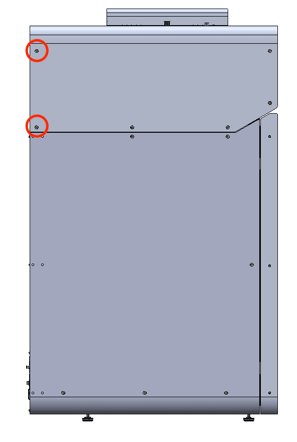
Step 8: Remove the upper rear panel screws

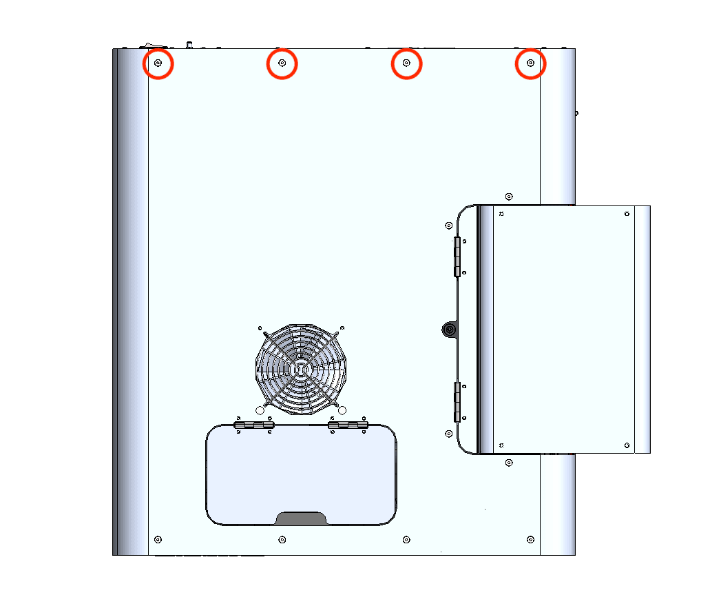
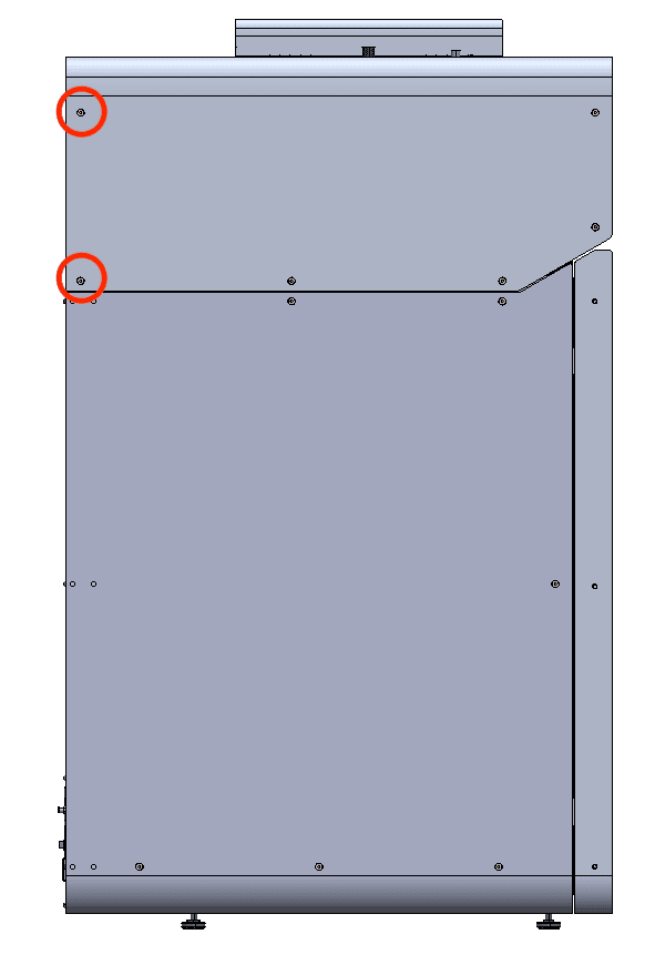
Using a 2.5 mm hex driver, remove the eight screws securing the upper rear panel to the printer:

Step 8: Remove the upper rear panel screws
  • Two 6 mm screws on the buffer side of the printer
  • Four 6 mm screws on the top of the printer
  • Two 6 mm screws on the hopper side of the printer

Set the screws aside.

Step 9: Remove the upper rear panel

Pull the upper rear panel straight back and away from the printer. Lay it down on a flat, clean surface.

Removing the original flipper motor assembly

Overview: Unplug and remove the flipper motor assembly that is being replaced.

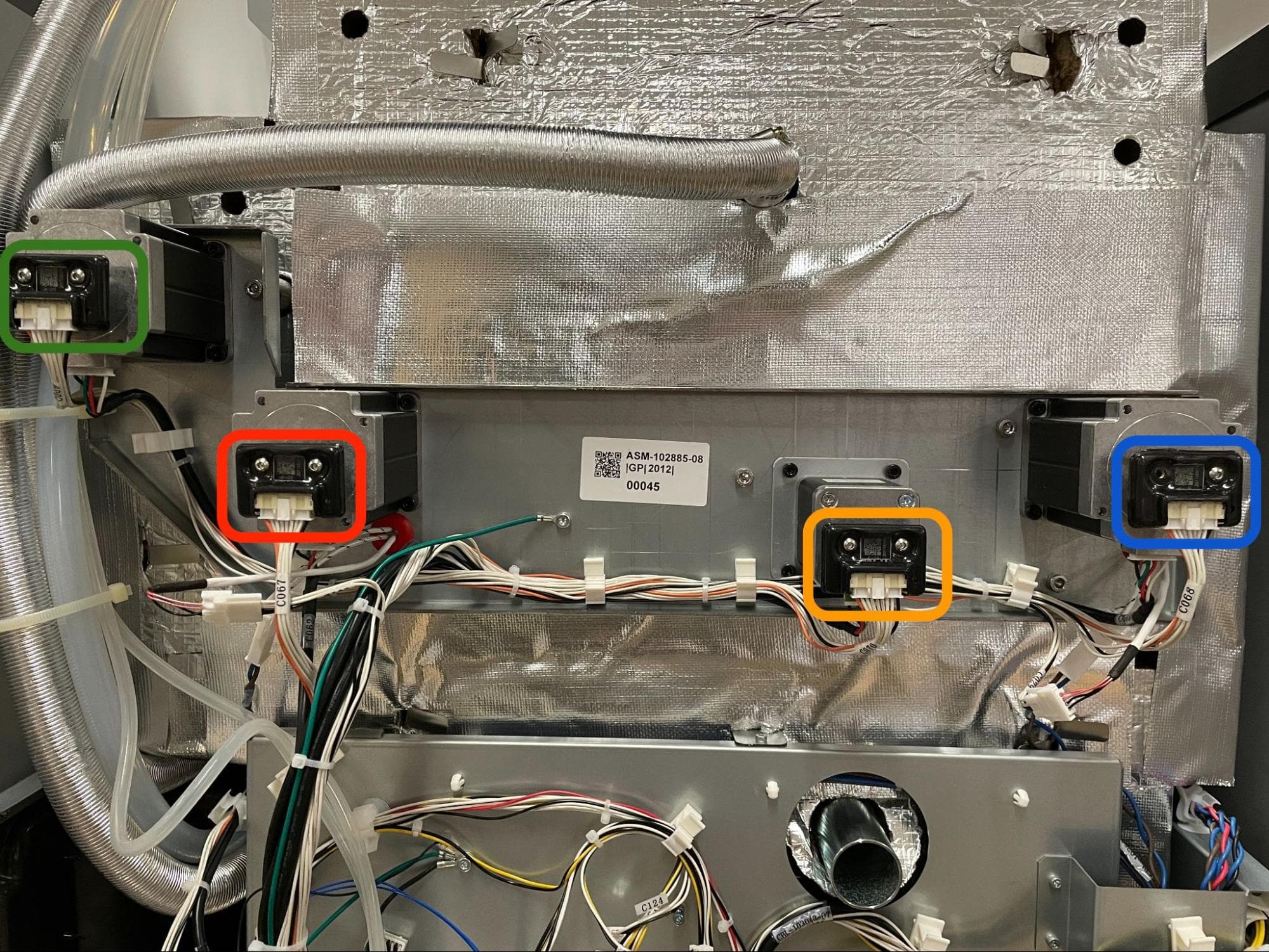
Step 1: Locate the flipper motor assembly to be replaced

With the rear panels removed, there are four motors visible at the back of the printer. From left to right, when looking at the back of the printer, they are the doser motor (circled in green here), hopper-side flipper motor (circled in red), build chamber Z-axis motor (circle in yellow), and buffer-side flipper motor (circled in blue). Identify the flipper motor assembly you are replacing.

Remove the original flipper motor assembly

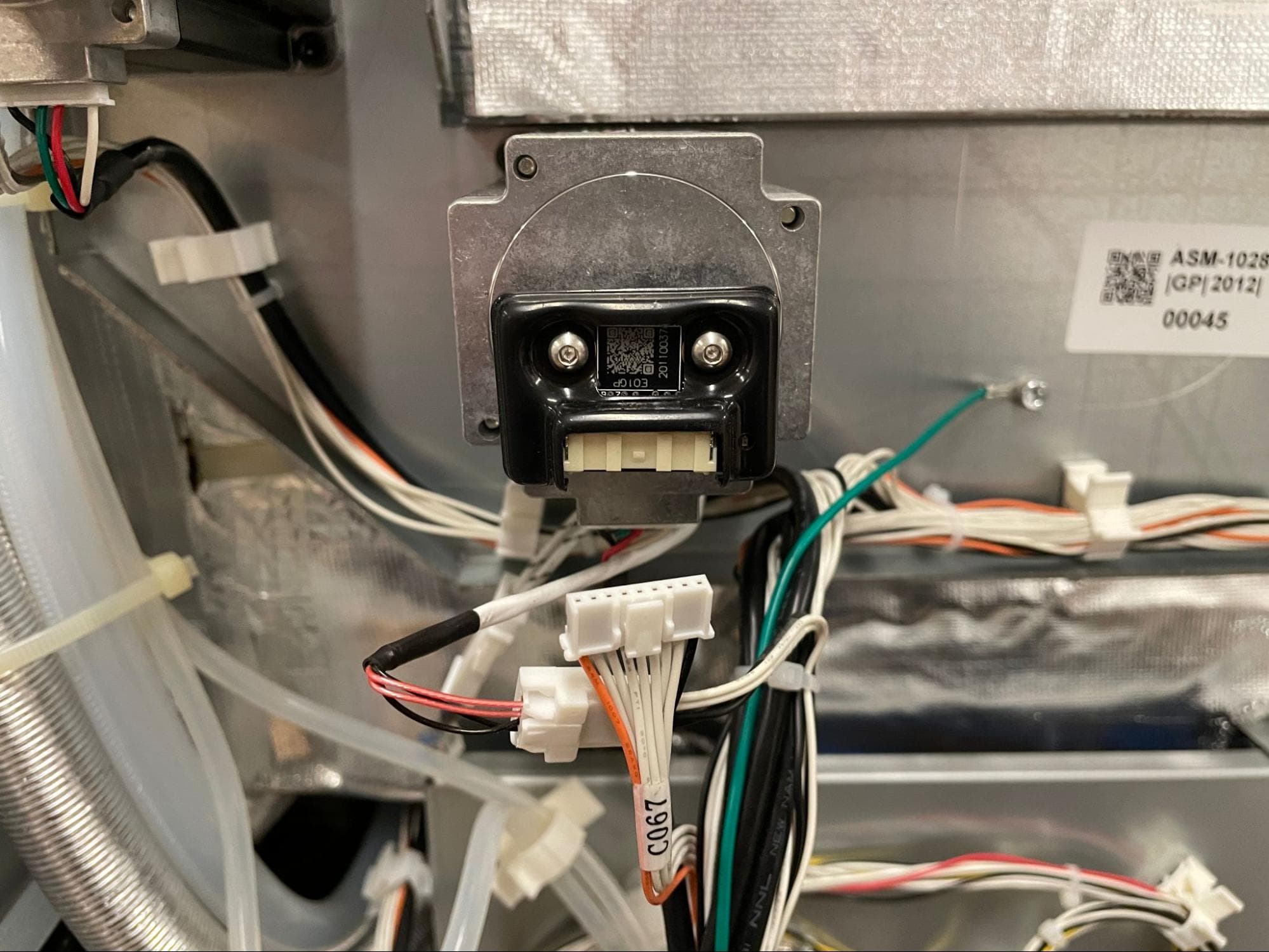
Step 2: Disconnect the motor and encoder cables

Disconnect the encoder cable by depressing the white tab and pulling the connector housing away from the socket. Disconnect the motor cable by gripping the white housing and pulling it away from the socket.

Remove the original flipper motor assembly

Step 3: Remove the flipper motor assembly

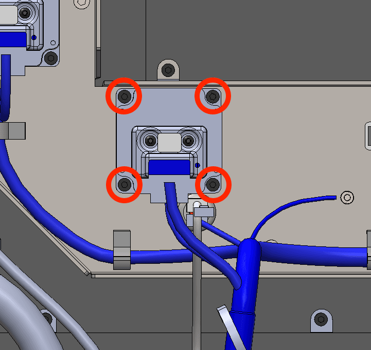
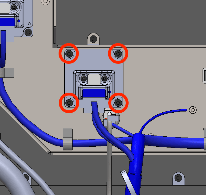
Using a 3 mm hex driver, loosen and remove the four 10 mm M4 socket head screws securing the motor assembly to the printer. Set the screws aside. Pull the motor assembly away from the printer and set it aside for disposal.

Remove the original flipper motor assembly

Installing the replacment flipper motor assembly

Overview: Mount, secure, and connect the replacement flipper motor assembly.

Step 1: Mount the new flipper motor assembly

Remove the flipper motor assembly. Orient it with the encoder and motor connector sockets facing down. Rotate the motor coupling until it is aligned with the square shaft on the printer and slide the motor into place. Ensure that the motor sits flush against the printer and the four screw holes in the motor are aligned with the corresponding screw holes in the printer frame.

Step 2: Secure the motor

Thread one 10 mm M4 socket head screw into each of the four screw holes in the motor. Using a 3 mm hex driver, tighten the screws until snug.

Install the new flipper motor assembly

Step 3: Reconnect the encoder and motor cables

Connect both the encoder and motor cables to the motor. They only fit into the appropriate socket in one orientation.

Reinstalling the rear panels

Overview: After installing the replacement flipper motor assembly, reinstall and secure the rear panels.

Step 1: Align the upper rear panel with the printer

Lift the upper rear panel and align it with the four screw holes on the top of the printer.

Step 2: Secure the upper rear panel top screws

Thread the four 6.0 mm screws into each of the screw holes on the top of the printer. Using a 2.5 mm hex driver, tighten the screws until finger tight. You may need to adjust the exhaust duct to correctly position the upper rear panel.

Step 1: Align the upper rear panel with the printer

Step 3: Secure the buffer side panel screws

Thread the two 6 mm screws into the screw holes on the buffer side and the two 6 mm screws into the screw holes on the hopper side. Using a 2.5 mm hex driver, tighten the screws until snug.

Step 3: Secure the buffer side panel screws

Step 4: Secure the hopper side panel screws

Thread the two 6mm screws into the holes on the hopper side. Using a 2.5 mm hex driver, tighten the screws until snug.

Step 4: Secure the hopper side panel screws

Step 5: Secure the upper rear panel grounding screws

The two black upper rear panel screws are circled in red. The two chrome upper rear panel grounding screws are circled in blue.

Thread the panel screws into the indicated screw holes on the upper rear panel. Refer to the image for the correct locations of the black and chrome screws. Using a 2.5 mm hex driver, screw in the two black panel screws and two chrome grounding screws securing the upper rear panel to the printer.

Step 5: Secure the upper rear panel grounding screws

Notice:

The placement of the chrome screws is critical to the printer's electrical grounding. Incorrect placement may lead to printer damage.

Step 6: Slide the exhaust duct into position

Step 6: Slide the exhaust duct into position

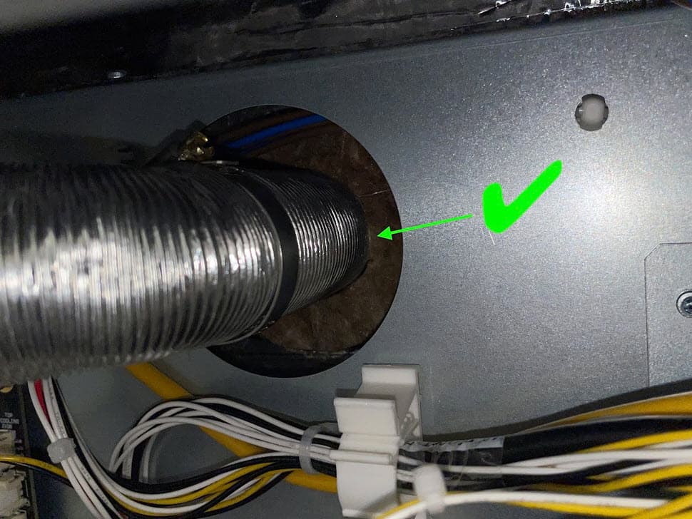
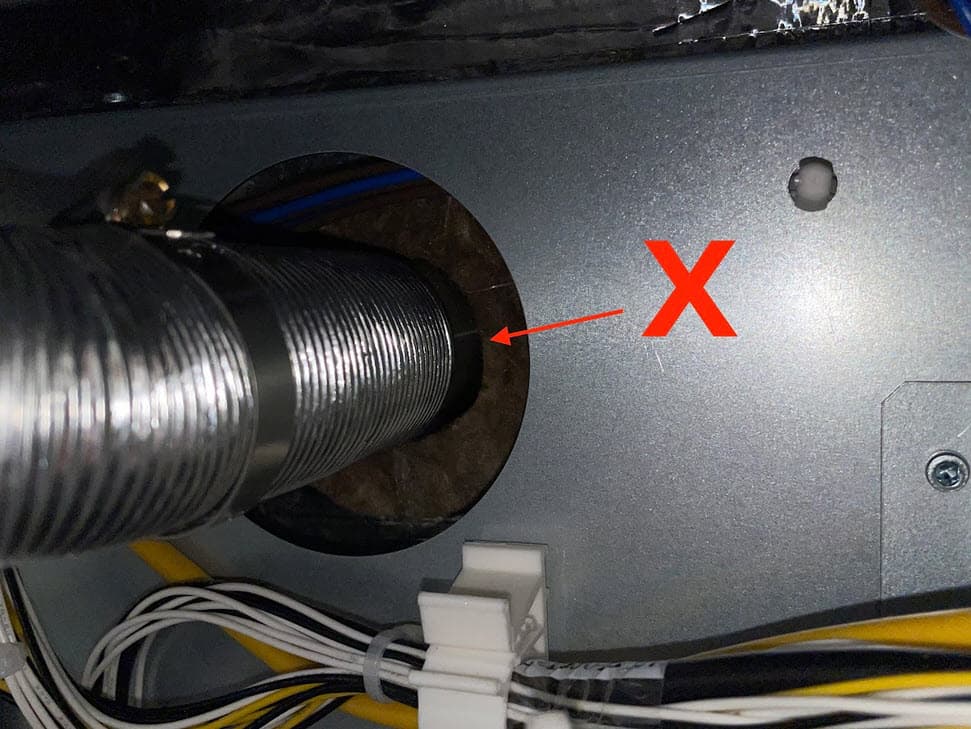
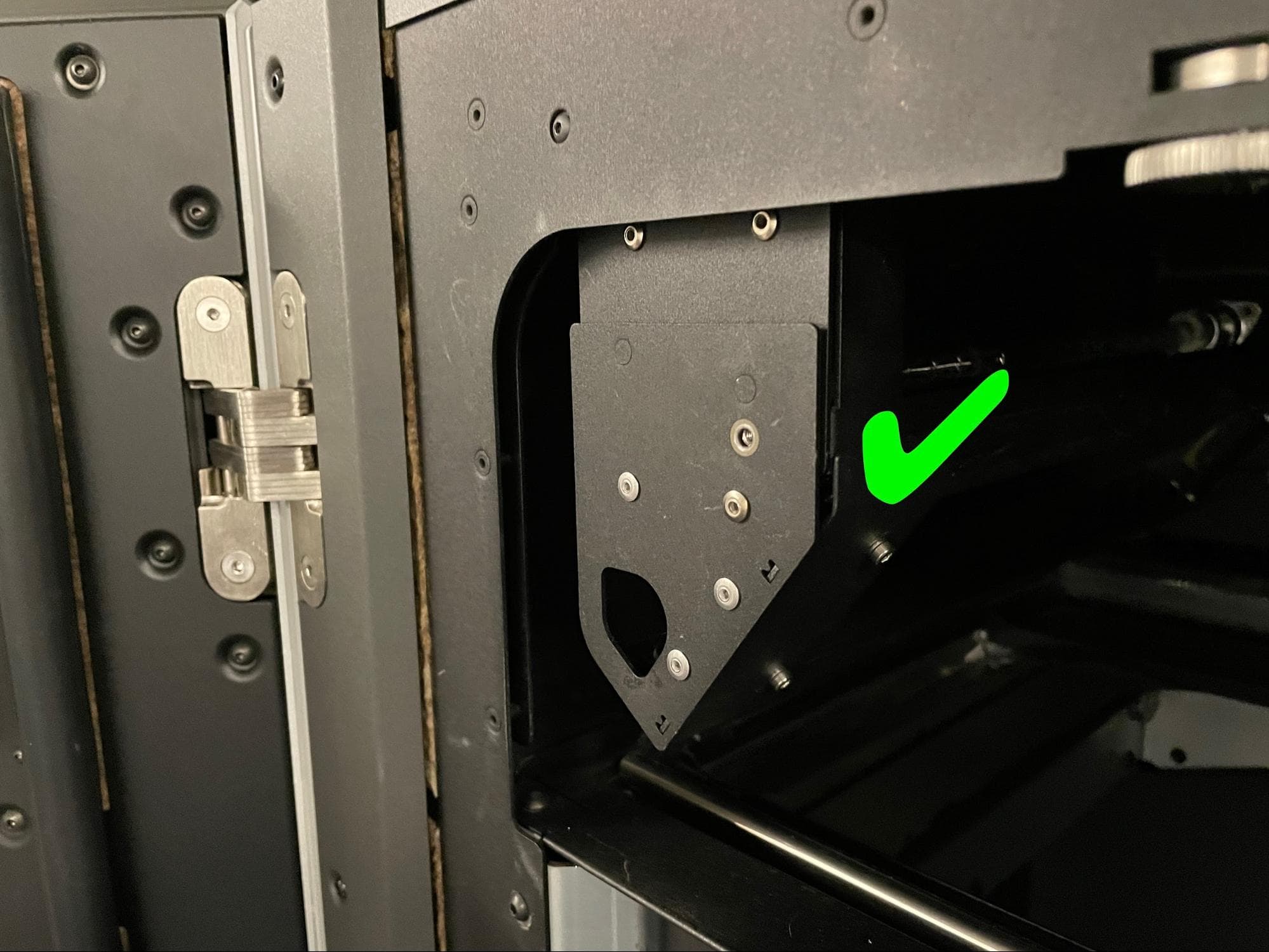
Slide the end of the exhaust duct with the ring clamp back onto the exhaust pipe. Ensure the exhaust duct presses against the insulation panel.

Step 7: Tighten the exhaust duct ring clamp

Using a 6.5 mm flathead screwdriver, tighten the ring clamp until finger tight.

Step 8: Secure the exhaust inlet screws

Open the filter cabinet door on the printer. Thread the four 8.0 mm screws into the screw holes. Using a 2.0 mm hex driver, screw in the four exhaust duct screws until finger tight.

Step 9: Check the exhaust duct seal

To ensure there is no gap between the exhaust duct’s mounting plate and the filter cabinet housing, shine a flashlight or other light source around the exhaust inlet inside the filter cabinet. If any light is visible behind the filter cabinet, the duct is not properly sealed. If necessary, use a 2.0 mm hex driver to tighten the exhaust duct screws. Close the filter cabinet door when finished.

Step 8: Secure the exhaust inlet screws

Step 10: Secure the lower rear panel grounding screws

The six black lower rear panel screws are circled in red. The four chrome lower rear panel grounding screws are circled in blue.

Thread the panel screws into the indicated screw holes on the lower rear panel. Refer to the image for the correct locations of the black and chrome screws. Using a 2.5 mm hex driver, screw in the six black panel screws and four chrome panel grounding screws securing the lower rear panel to the printer.

Step 1: Remove the lower rear panel screws

Notice:

The placement of the chrome screws is critical to the printer's electrical grounding. Incorrect placement may lead to printer damage.

Step 11: Reinstall the Wi-Fi antenna (optional)

Screw the Wi-Fi antenna onto the jack on the back of the unit.

Step 12: Reconnect the nitrogen supply (Fuse 1+ 30W only)

Reconnect the nitrogen hose to the quick-disconnect fitting, if previously installed.

Calibrating the new flipper motor

Overview: After installing the replacement flipper motor, calibrate its home position.

Step 1: Check the flipper motor

Reconnect the printer to power and turn it on using the switch on the back of the machine. Once the printer has booted, tap, Maintenance > Move Motors on the touchscreen. Using the toggles, move the relevant flipper back and forth to ensure that the motor is properly connected and functional. If not, shut down the printer and confirm that all cables are connected.

Step 2: Calibrate the flipper

On the touchscreen, tap Settings > Calibration > Flipper Calibration. This feature is available on firmware version 1.21.0 and later. Follow the instructions on-screen and in the article Calibrating a powder flipper (Fuse 1 generation) to set the flipper’s home position.

Step 3: Check the flipper home position

At the end of the calibration process, the flipper may move in a full rotation to confirm its new home position. The movement does not indicate that the calibration was done correctly or incorrectly.

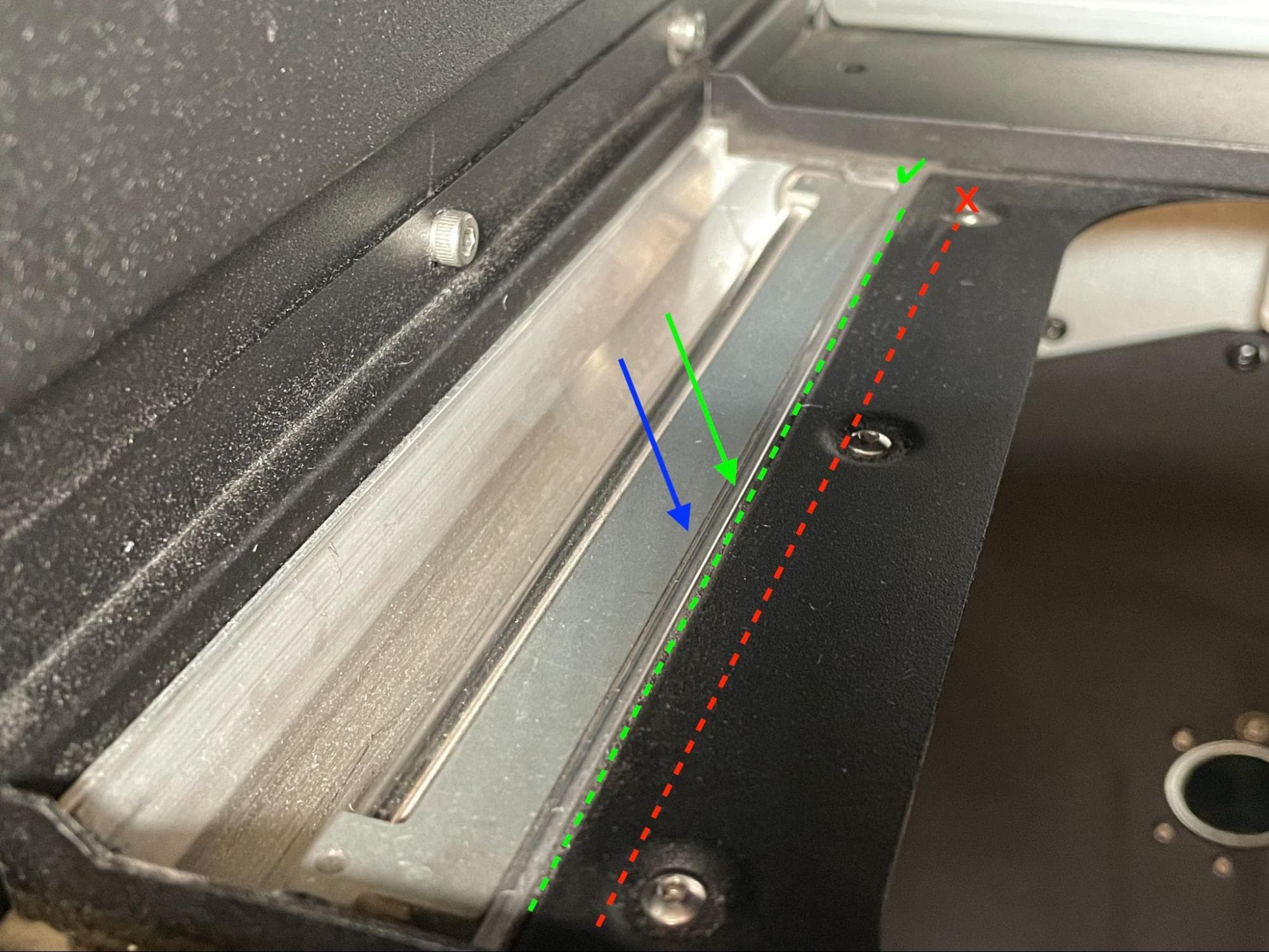
If the flipper appears to be horizontal at the end of the calibration process, then the calibration was successful. The flipper should sit parallel and flush to the silver aluminum trough, rather than the black powder shelf or anything else. If it ends up at a noticeable angle to the print plane, then it is not properly calibrated, and you should perform the procedure again.

Flipper calibration

Reinstalling the quartz tube heater spatial filter

Overview: After calibrating the flipper motor assembly, align and reinstall the spatial filter.

Step 1: Align the spatial filter with the frame

Align the slots on the spatial filter with the rails on the lamp frame.

Step 2: Install the spatial filter

Replace the heater filters

Push the spatial filter along the rails towards the back of the printer. Ensure that the alignment pins on the back of the front face of the spatial filter go into the corresponding holes in the lamp frame. The front of the spatial filter sits flush against the front of the lamp frame when it is properly installed.

Step 3: Secure the spatial filter

Thread the 8.0 mm M3 cap screw into the screw hole in the front of the spatial filter. Tighten the screw with a 2.5 mm hex driver until finger tight.

Replace the heater filters

Finalizing the repair

Overview: After installing the replacement flipper motor assembly, start a print and perform final checks.

Step 1: Test the repair

Insert and connect a build chamber, close the print enclosure door, and start a print. Monitor the printer to ensure that the new flipper moves smoothly and the print proceeds normally. Contact Formlabs Support or your certified service provider to share the results of the procedure.