
Required Supplies:
Formlabs:
- Z-axis limit switch
- 2.5 mm hex driver (included in the Form 4 tool cap assembly)
Third-party:
- Flathead screwdriver
- Tweezers (optional)
- Nitrile gloves

The Z-axis limit switch helps position the Z-axis and build platform mount on Form 4 generation printers. The limit switch is located at the top of the Z-tower on the printer. A malfunctioning Z-axis limit switch may prevent the printer from printing properly.
Use this guide to replace the Form 4 Z-axis limit switch.
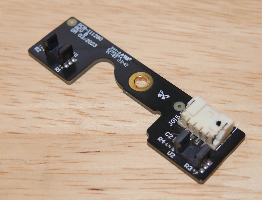
Required Supplies:
Formlabs:
Third-party:
Estimated time: 30 minutes
Preparing the workspace
Overview: Prepare the Form 4 and workspace for replacing the Z-axis limit switch.
Step 1: Remove the build platform
Remove the build platform first to avoid dripping resin onto the Light Processing Unit (LPU).
Step 2: Remove the resin cartridge
Remove the resin cartridge and close the vent cap to prevent resin from dripping off of the bite valve and into the printer.
Step 3: Remove and store the resin tank and mixer
Unlatch the mixer and resin tank. Remove the resin tank and cover it with its lid. Set the tank aside on a clean, flat surface.
Notice:
Wear gloves and hold the resin tank by the tank grips on either side to avoid contamination or damage to the underside of the tank.
Step 4: Prepare the workspace
Clear a workspace around your printer. Ensure that the workspace is well-ventilated and free of dust.
Step 5: Clean the printer
Warning:
Resin may cause skin irritation or an allergic skin reaction. Wear gloves when handling liquid resin or resin-coated surfaces. Wash skin with plenty of soap and water.
Open the printer cover and clean any resin pooled on and around the LPU with non-abrasive wipes. Dampen the wipes with isopropyl alcohol if necessary to fully remove the resin.
Danger:
Fire hazard. IPA is flammable. Keep containers closed, and keep out of the reach of children.
Step 6: Unplug the printer
Disconnect the power cable before continuing with maintenance. Do not perform maintenance on the printer while it is connected to power. Wait five minutes after disconnecting the printer from power before proceeding.
Removing the back panel
Overview: Remove the back panel to access the tower cap retention tabs.
Notice:
Formlabs printers contain sensitive electronic components. Ground yourself before touching any electronics in the printer by using a grounding strap or touching a grounded piece of metal.
Step 1: Remove the back panel screws
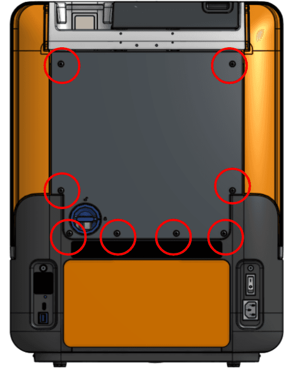
Use a 2.5 mm hex driver to remove the eight screws securing the back panel to the printer. Set the screws aside.
Step 2: Remove the back panel
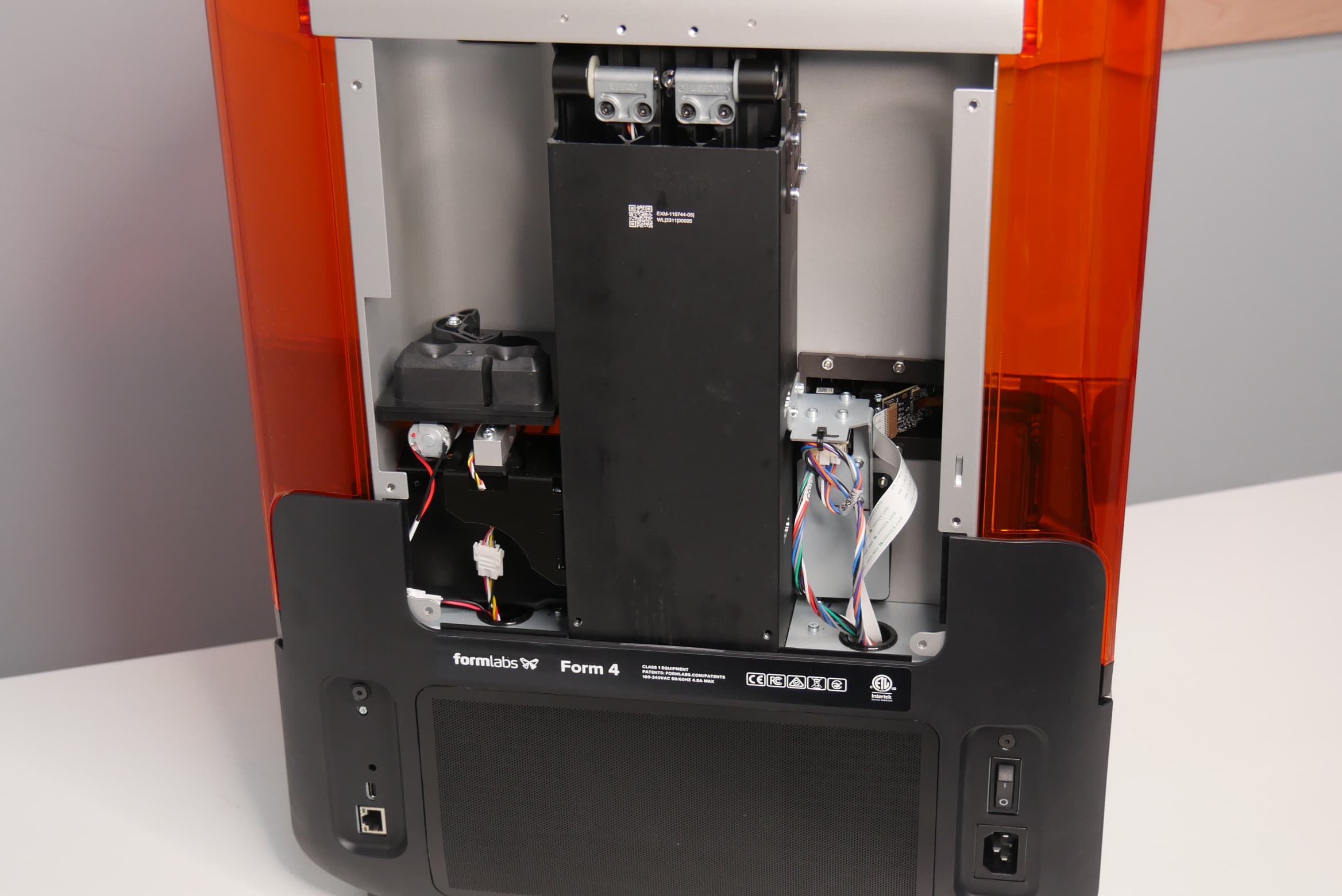
Remove the back panel by sliding it down and away from the back of the printer. Set the back panel aside.
Removing the tower cap
Overview: After removing the back panel, remove the tower cap.
Step 1: Remove the tool card
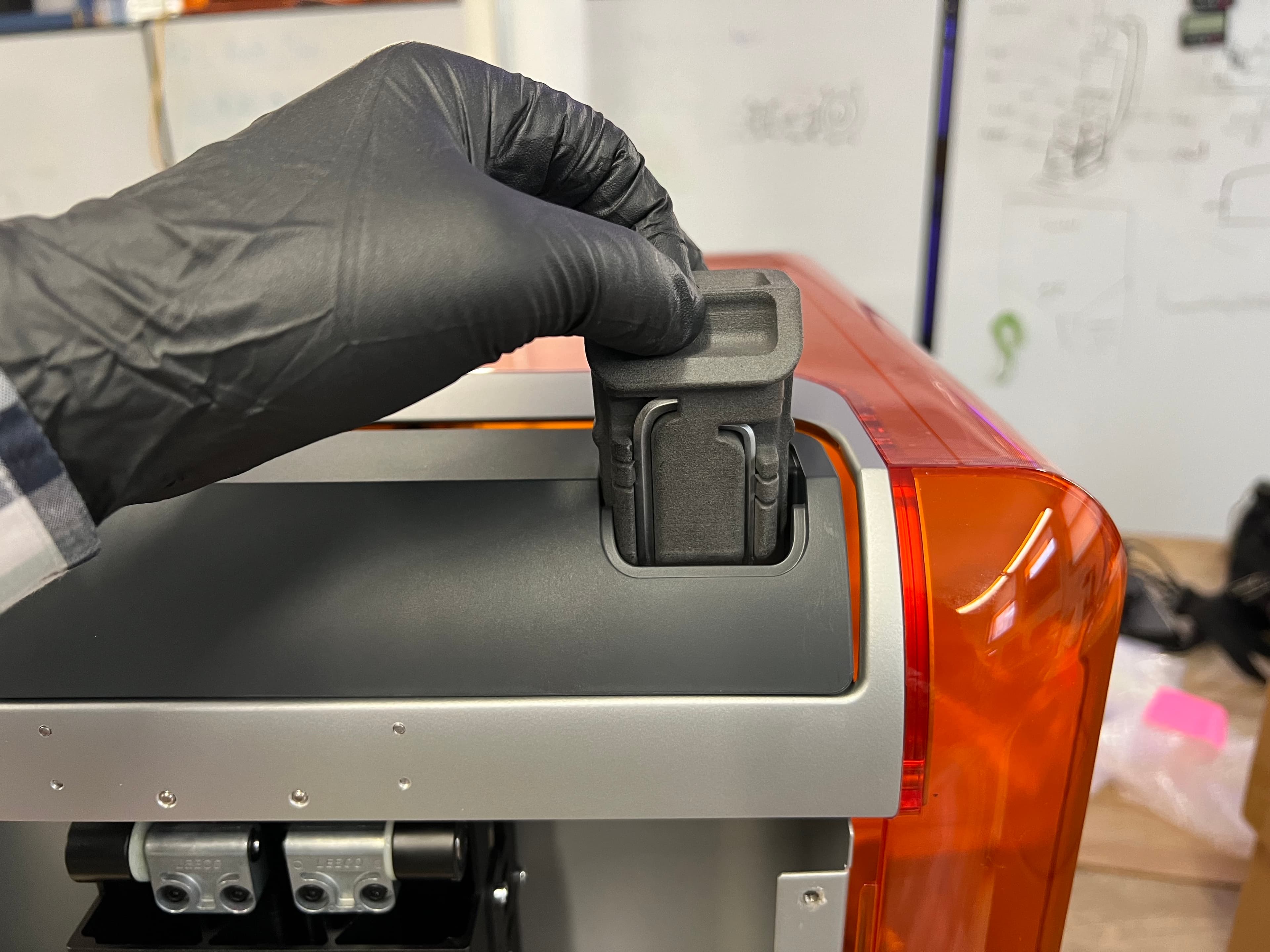
If you have not done so already, remove the tool caddy from the tower cap to access the 2.5 mm hex driver provided with the printer. Set the tool caddy aside.
Step 2: Open the printer cover
Open the printer cover for easy access to the underside of the tower cap.
Step 3: Unclip the tower cap clips
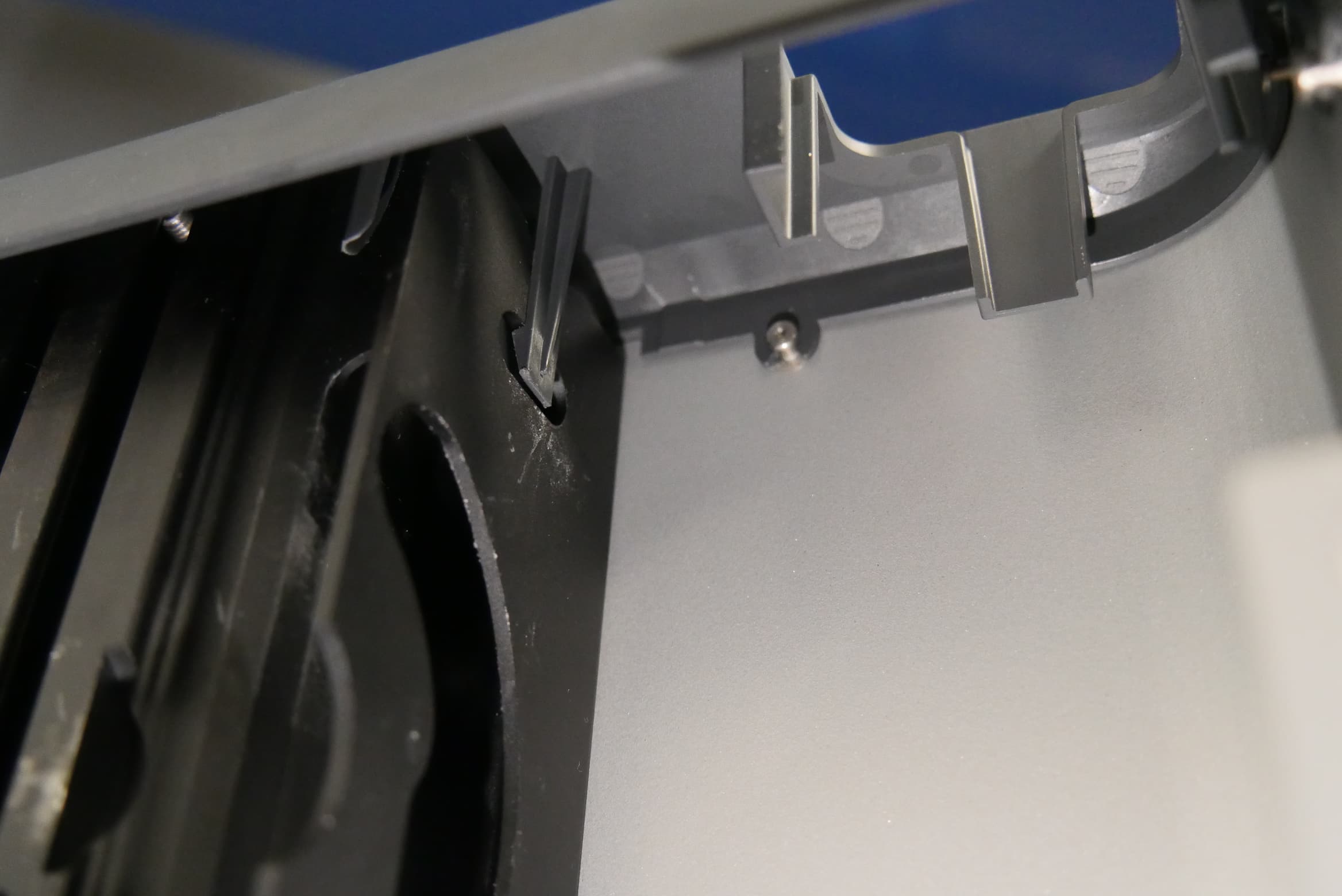
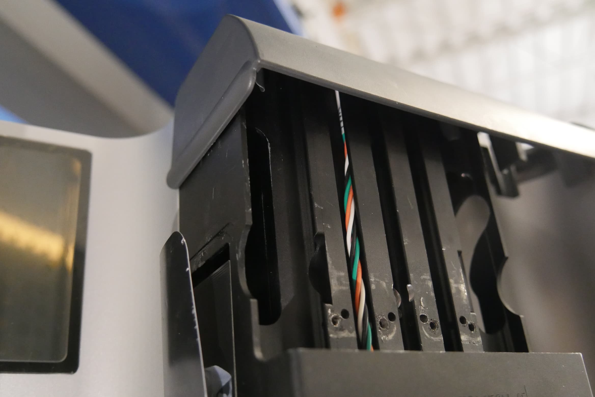
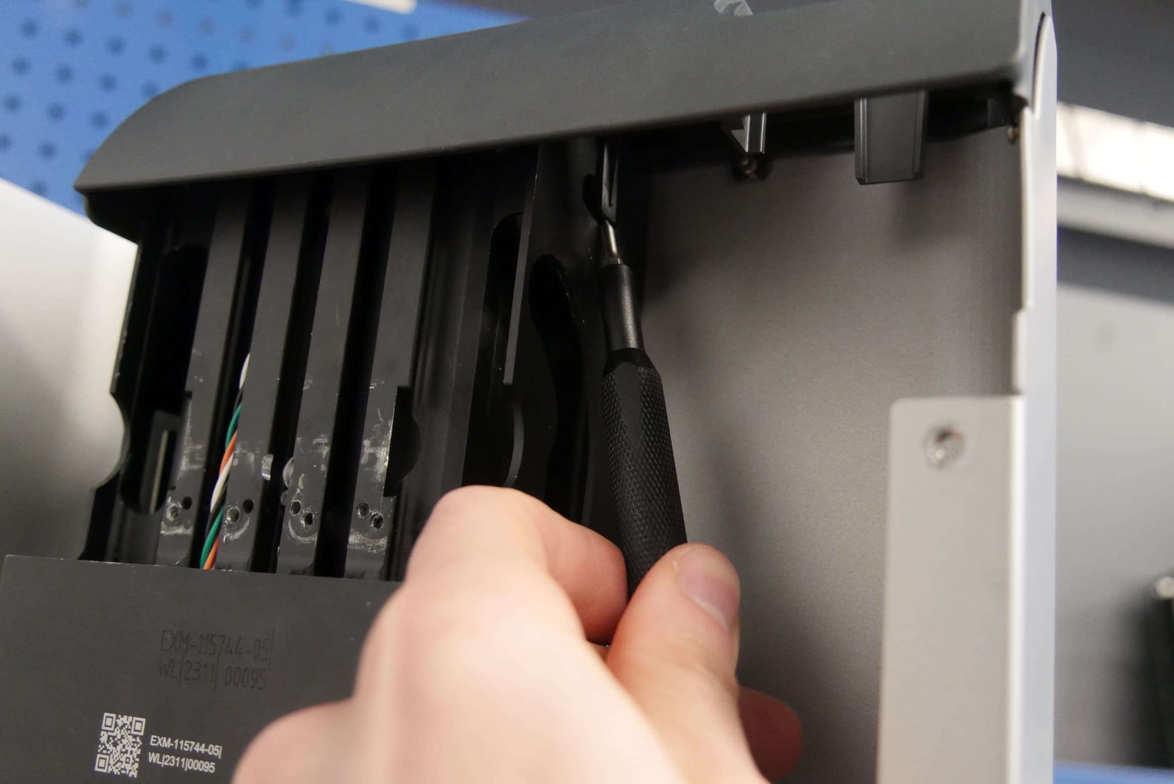
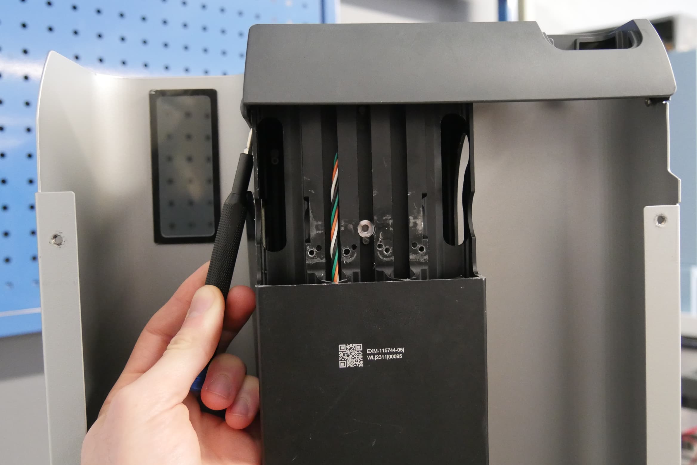
The tower cap is secured to the Z-tower via two clips, one on each side of the Z-tower. From below the tower cap, use a flathead screwdriver or other similar tool to gently pry the clips away from the Z-tower.
Step 4: Remove the tower cap
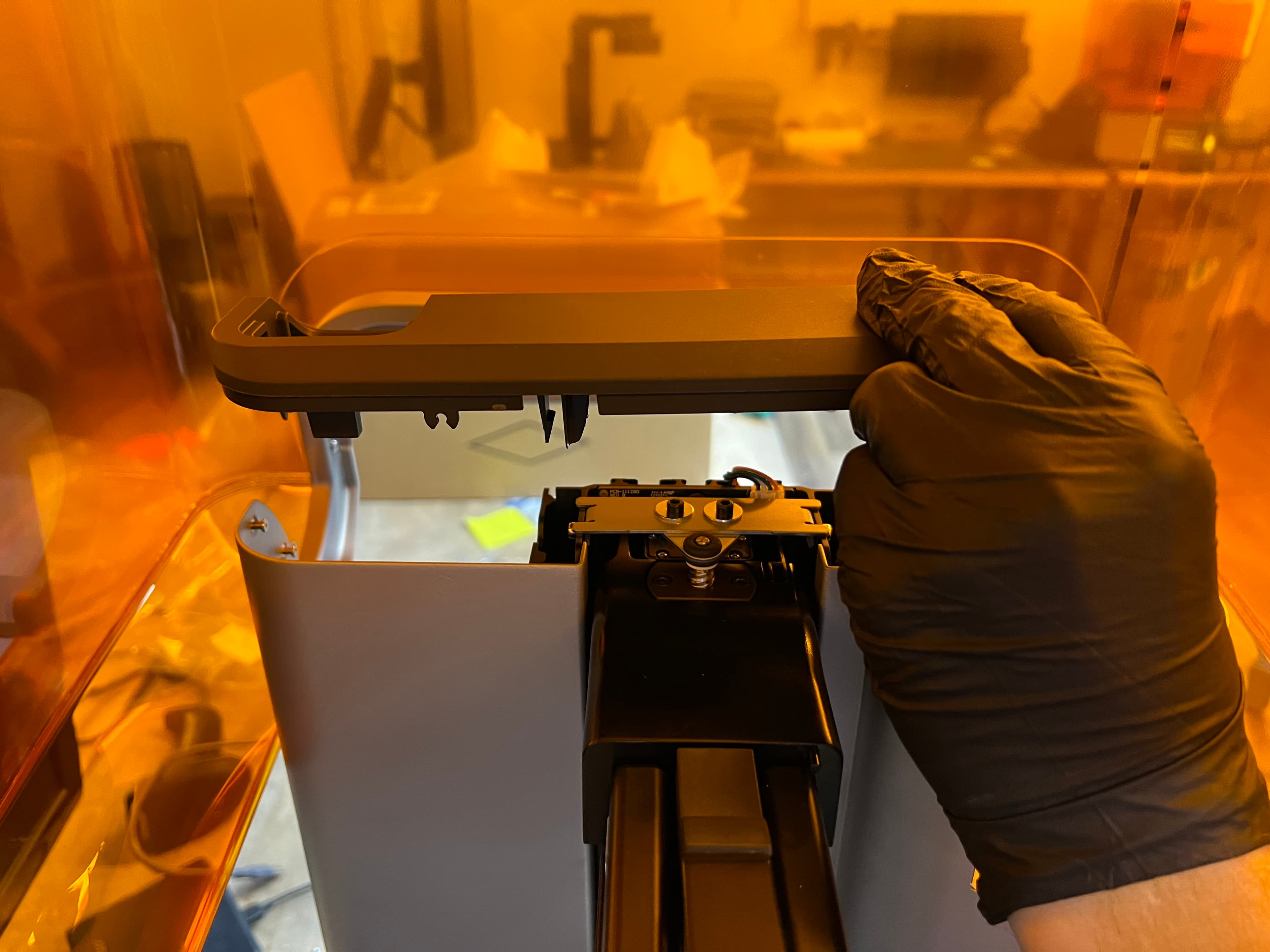
Lift the tower cap straight up to separate it from the printer. Set the tower cap aside.
Removing the Z-axis limit switch
Overview: Remove the limit switch screw, disconnect the limit switch cable, and install the Z-axis limit switch.
Step 1: Remove the limit switch retention screw
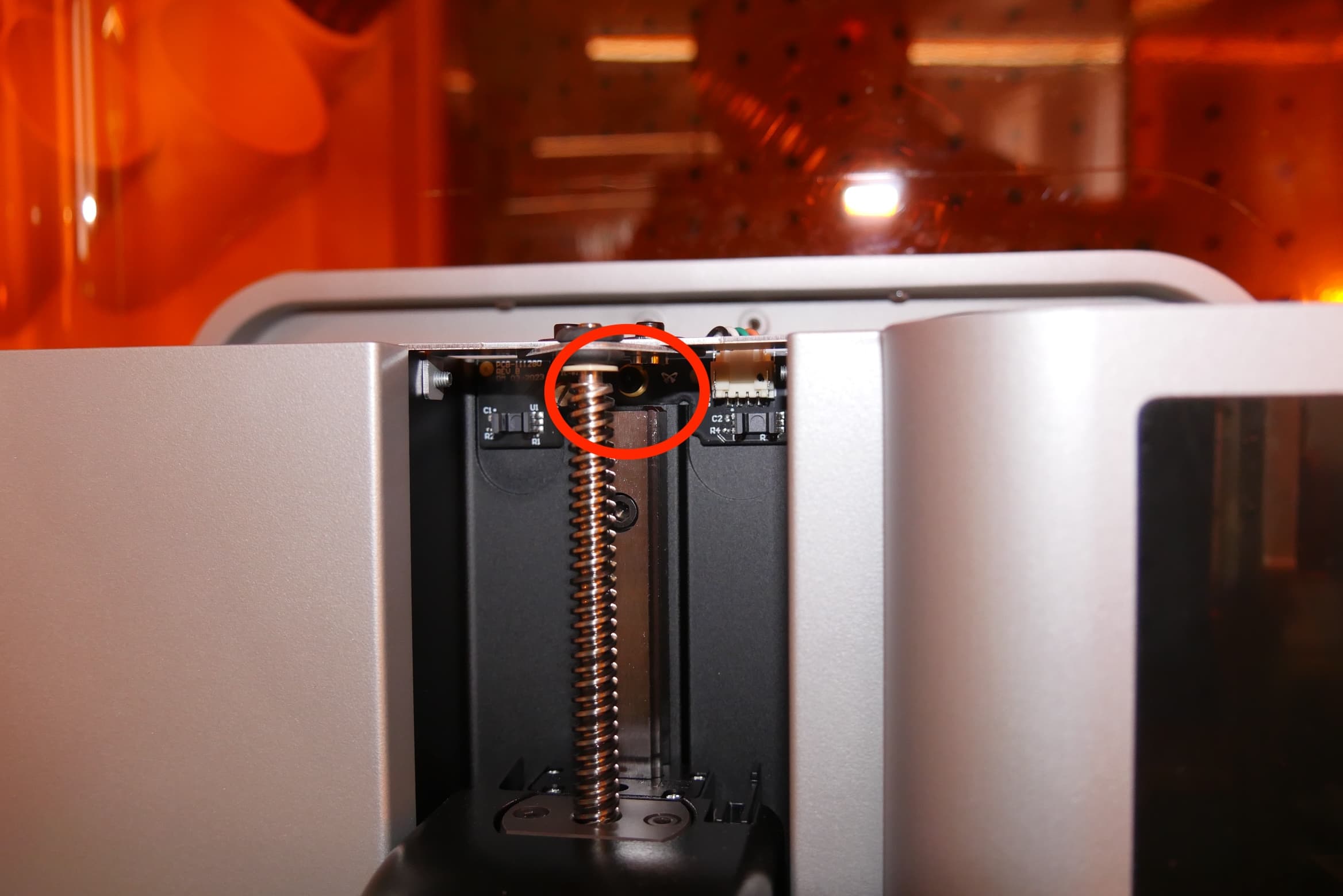
Use a 2.5 mm hex driver to remove the screw securing the limit switch to the tower. The limit switch retention screw is located directly behind the Z-axis lead screw. Set the screw aside.
Step 2: Disconnect the Z-axis limit switch cable
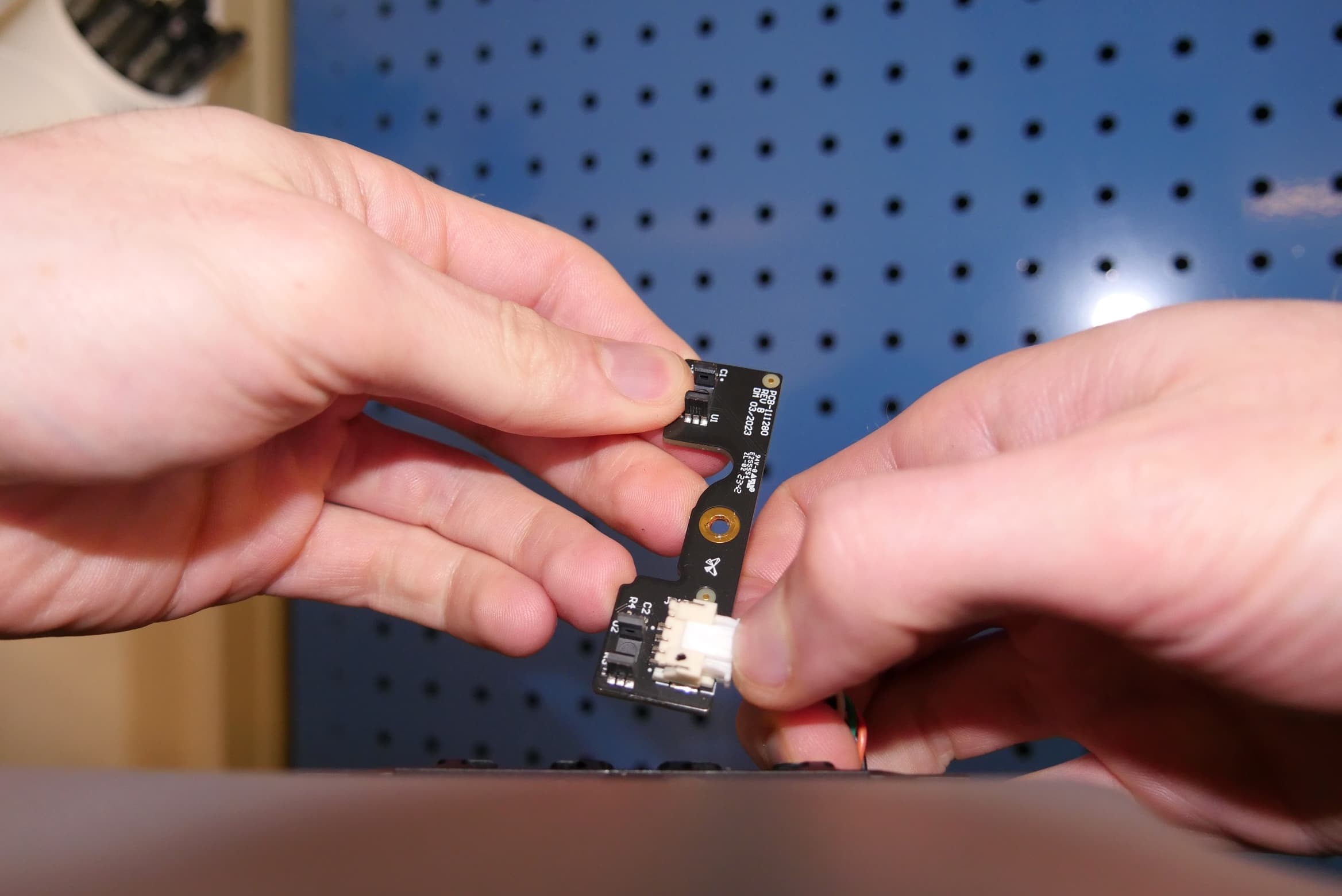
Lift the Z-axis limit switch upwards, out from behind the Z-axis lead screw. Squeeze the plastic retaining clip and unplug the Z-axis limit switch cable from the board. Do not pull on the wires. Set the Z-axis limit switch aside for disposal with electronic waste.
Installing the replacement Z-axis limit switch
Overview: Mount and secure the replacement Z-axis limit switch.
Step 1: Connect the Z-axis limit switch cable
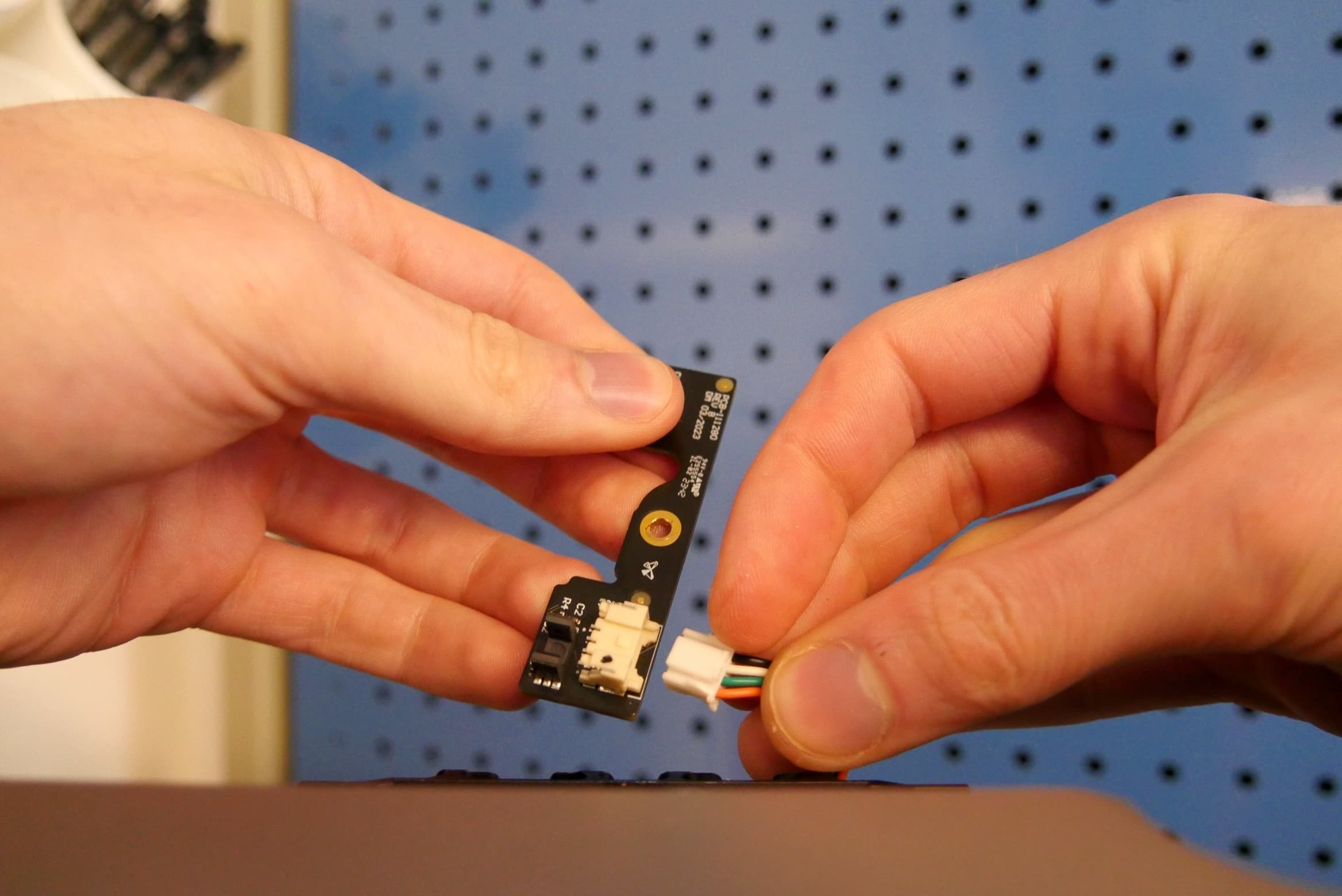
Connect the Z-axis limit switch cable to the circuit board. The connector makes an audible and tactile click when secured.
Step 2: Mount the replacement Z-axis limit switch
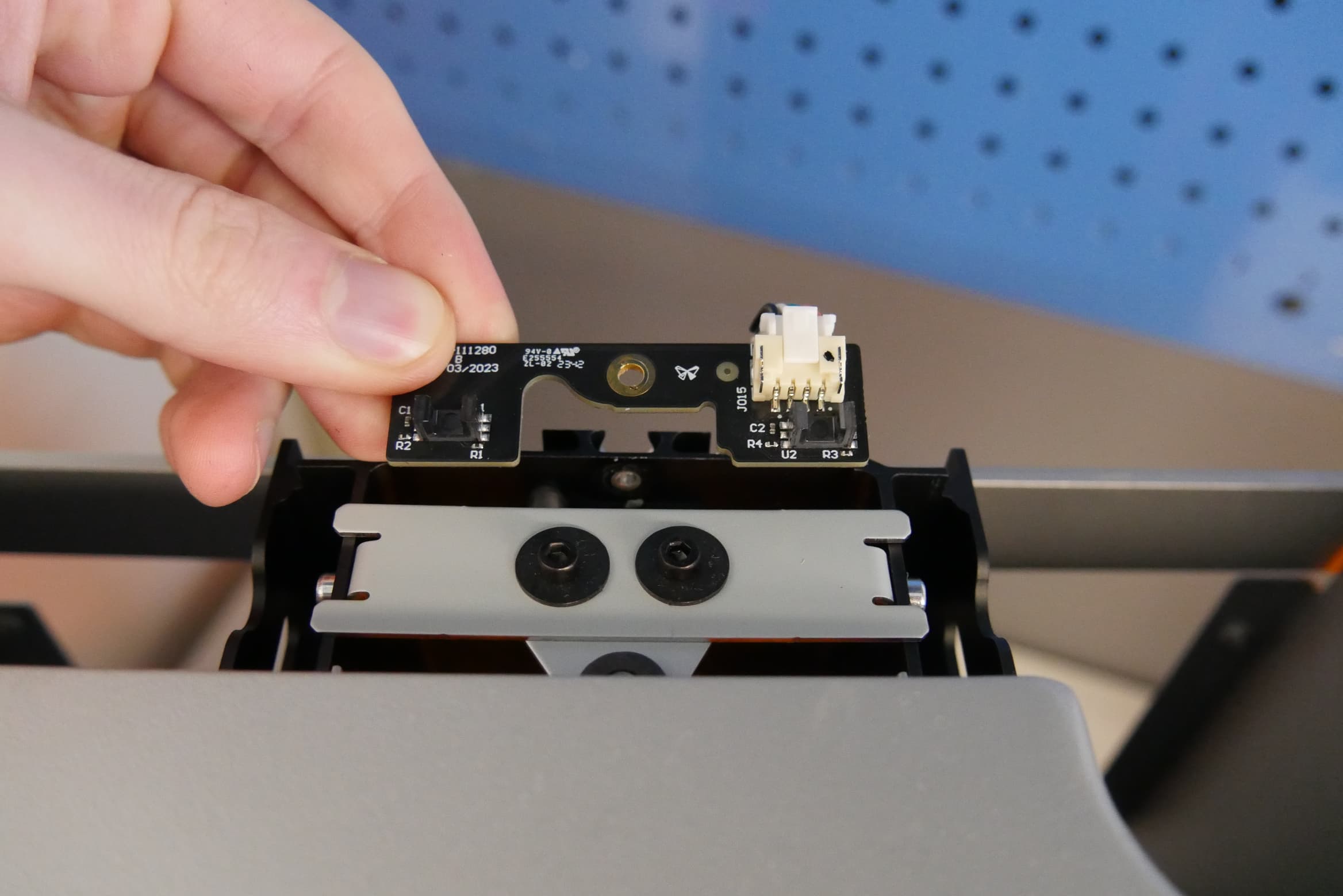
Align the screw hole in the limit switch board with the corresponding screw hole behind the Z-axis lead screw.
Step 3: Secure the replacement Z-axis limit switch
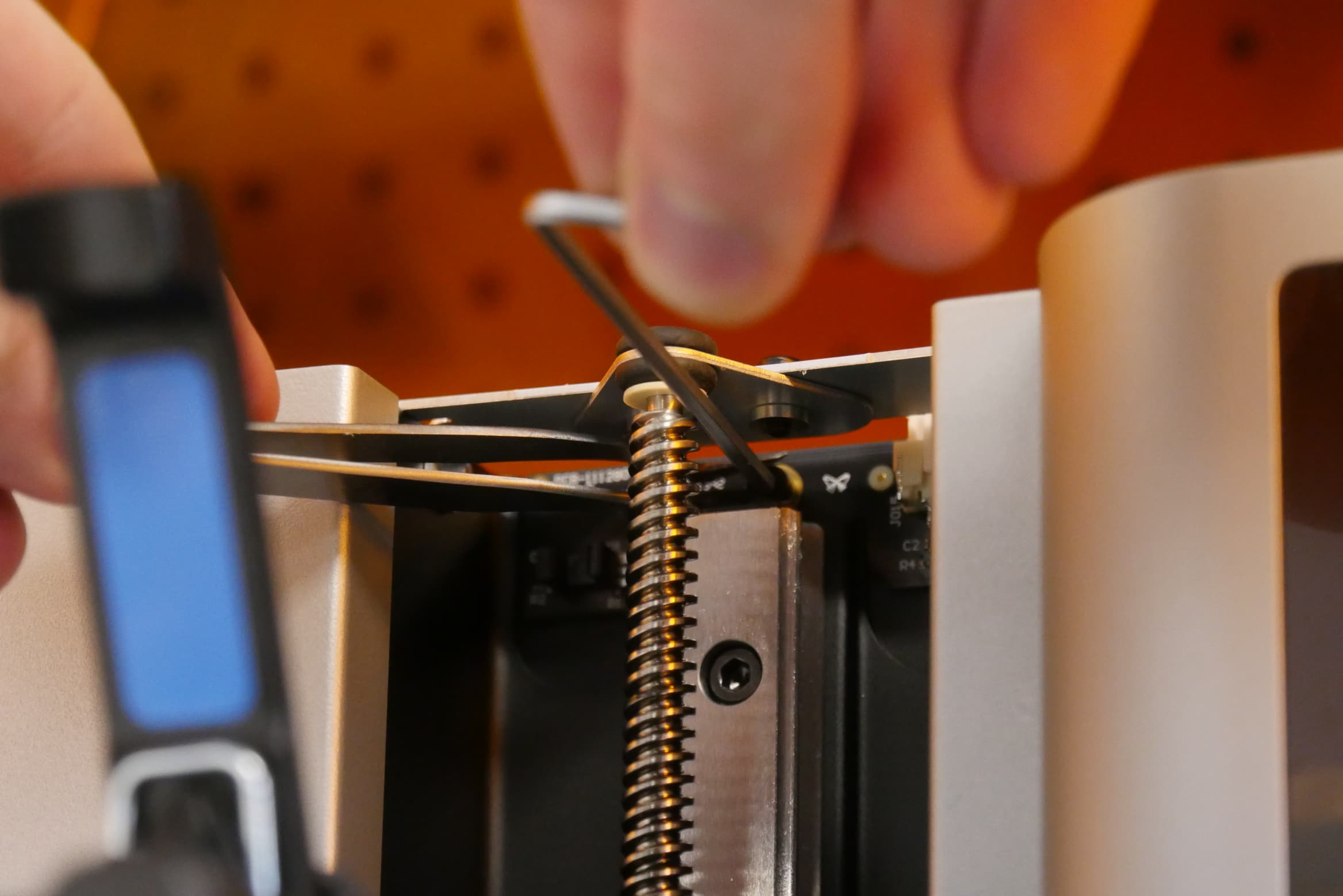
Thread the Z-axis limit switch retention screw into the screw hole. Consider using a pair of tweezers to hold the screw in place behind the Z-axis lead screw. Use a 2.5 mm hex driver to tighten until snug.
Reinstalling the tower cap
Overview: After installing the replacement Z-axis limit switch, reinstall the tower cap.
Step 1: Align the tower cap
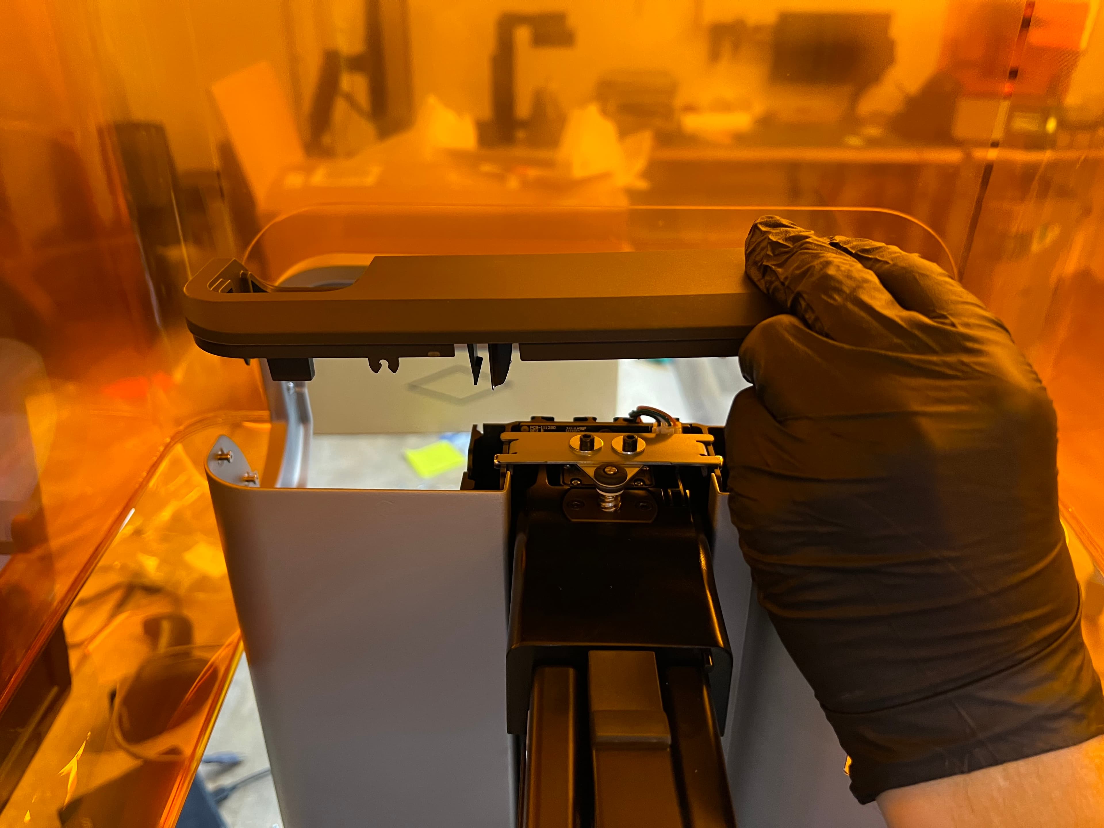
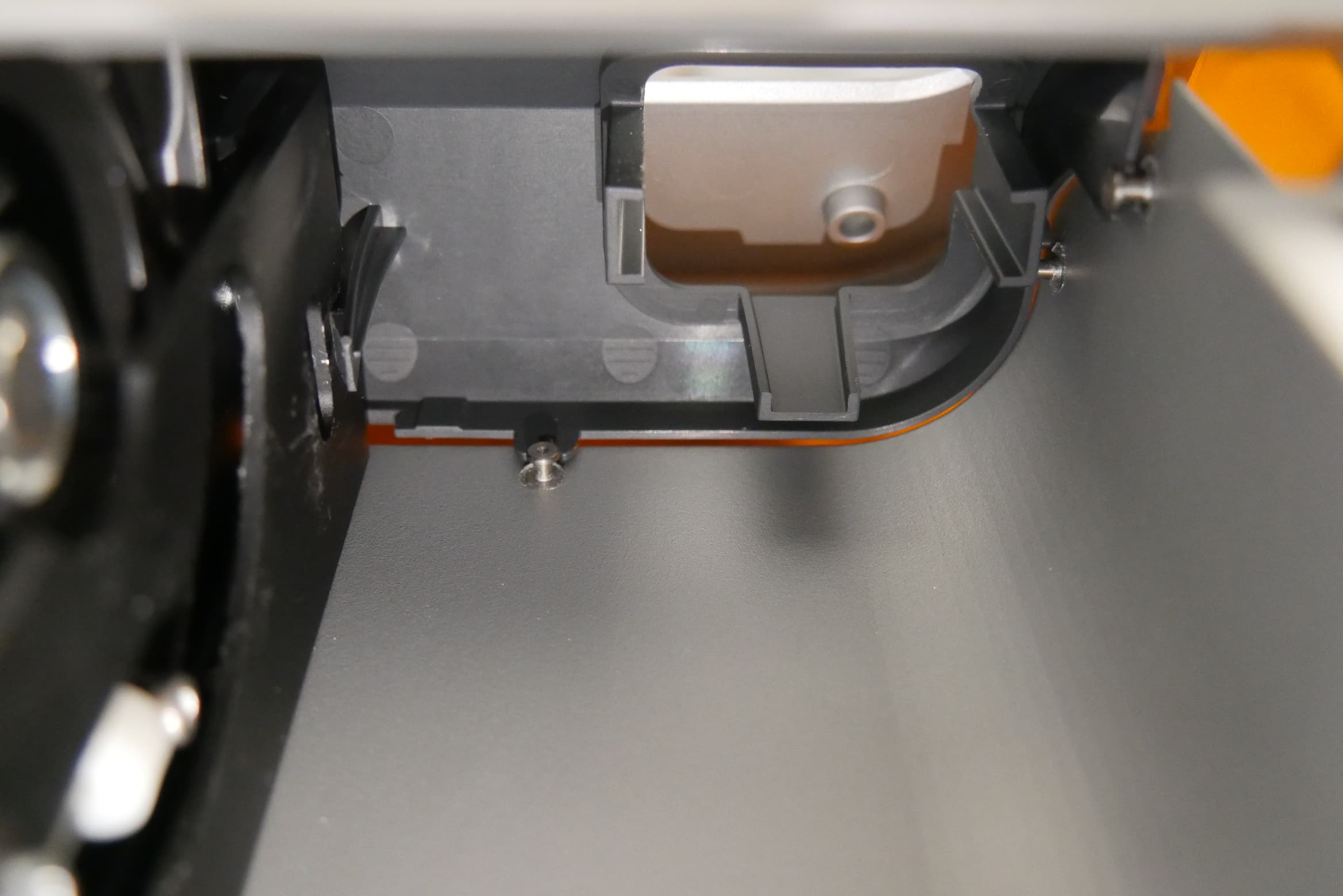
Place the tower cap on top of the Z-tower. From below, check that the clips align with the outside of the Z-tower and the retention features on the tower cap align with the pins in the printer.
Step 2: Secure the tower cap
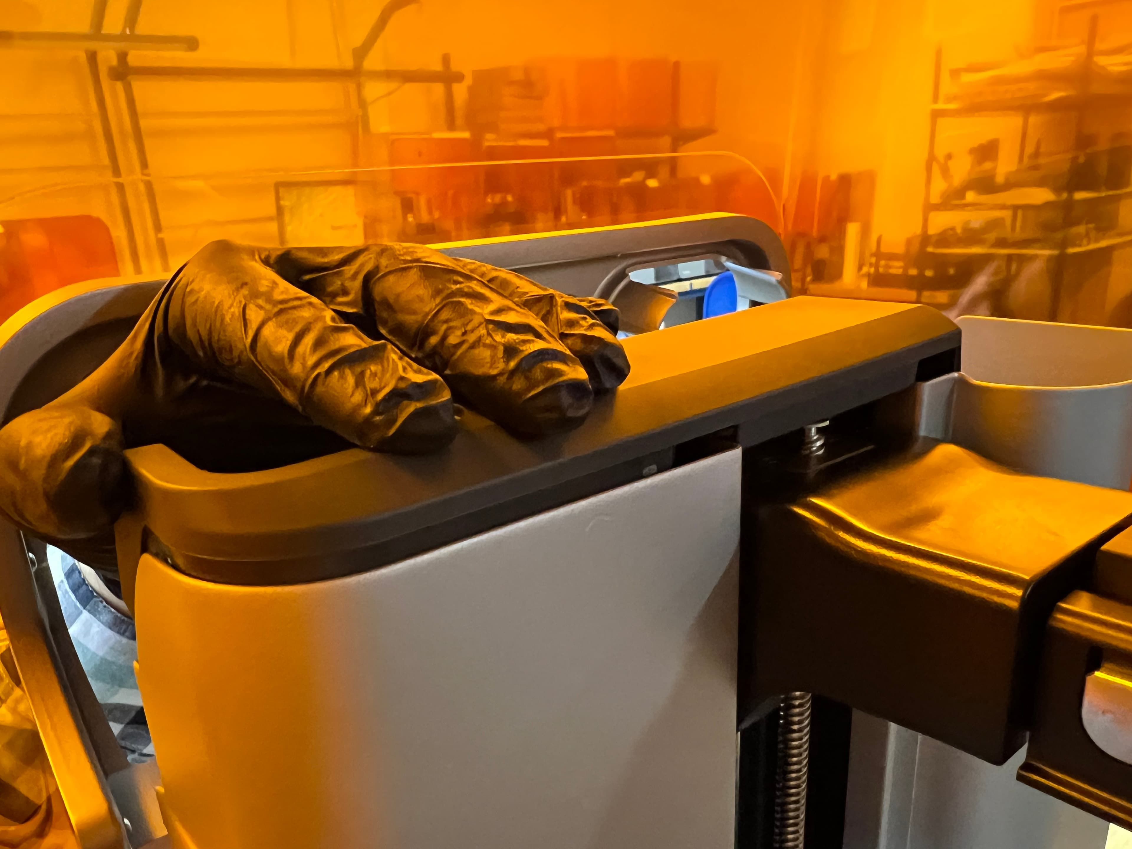
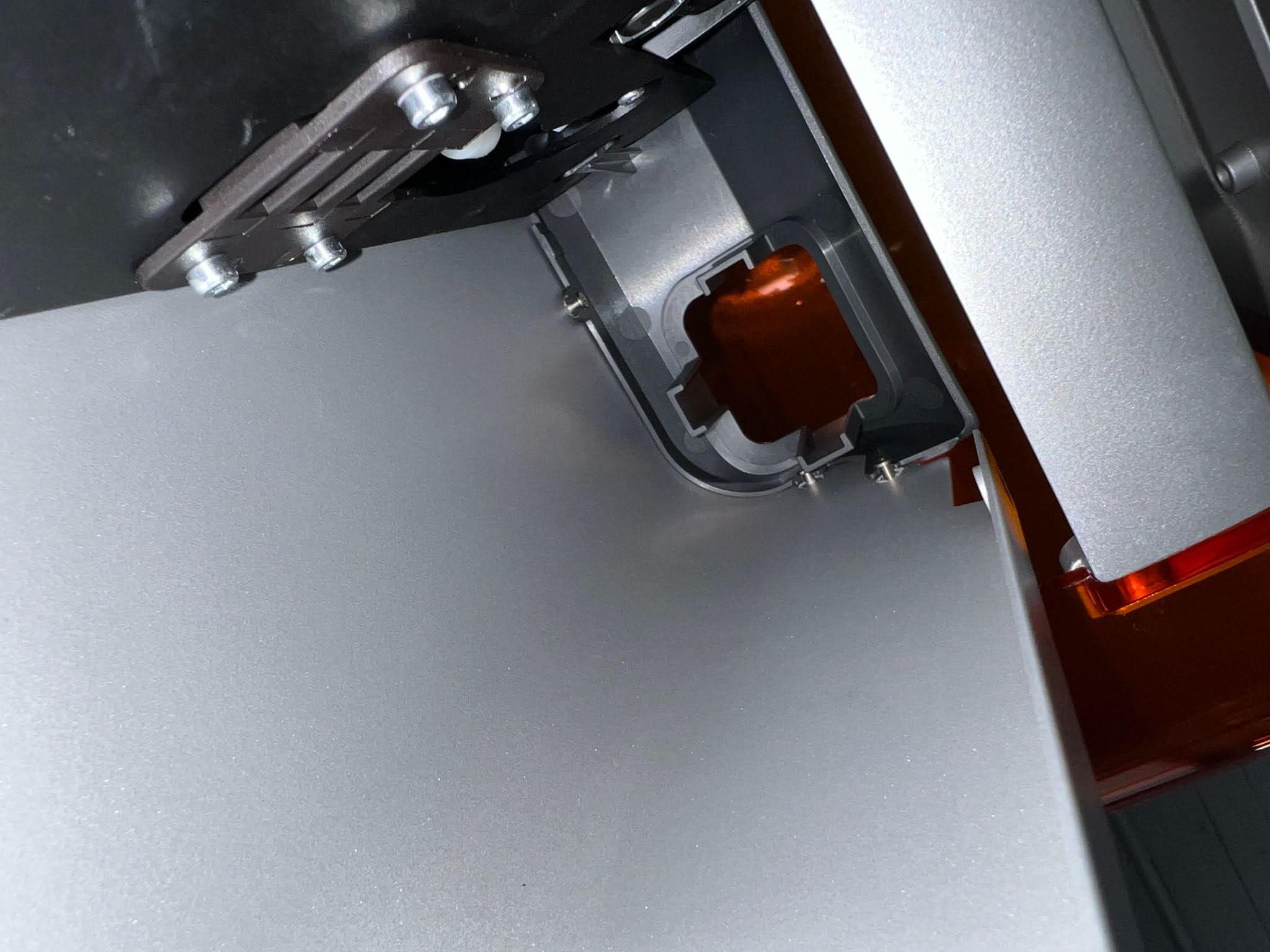
Press down on the tower cap to engage the clips. The tower cap sits flush against the Z-tower when properly installed.
Step 3: Replace the tool caddy
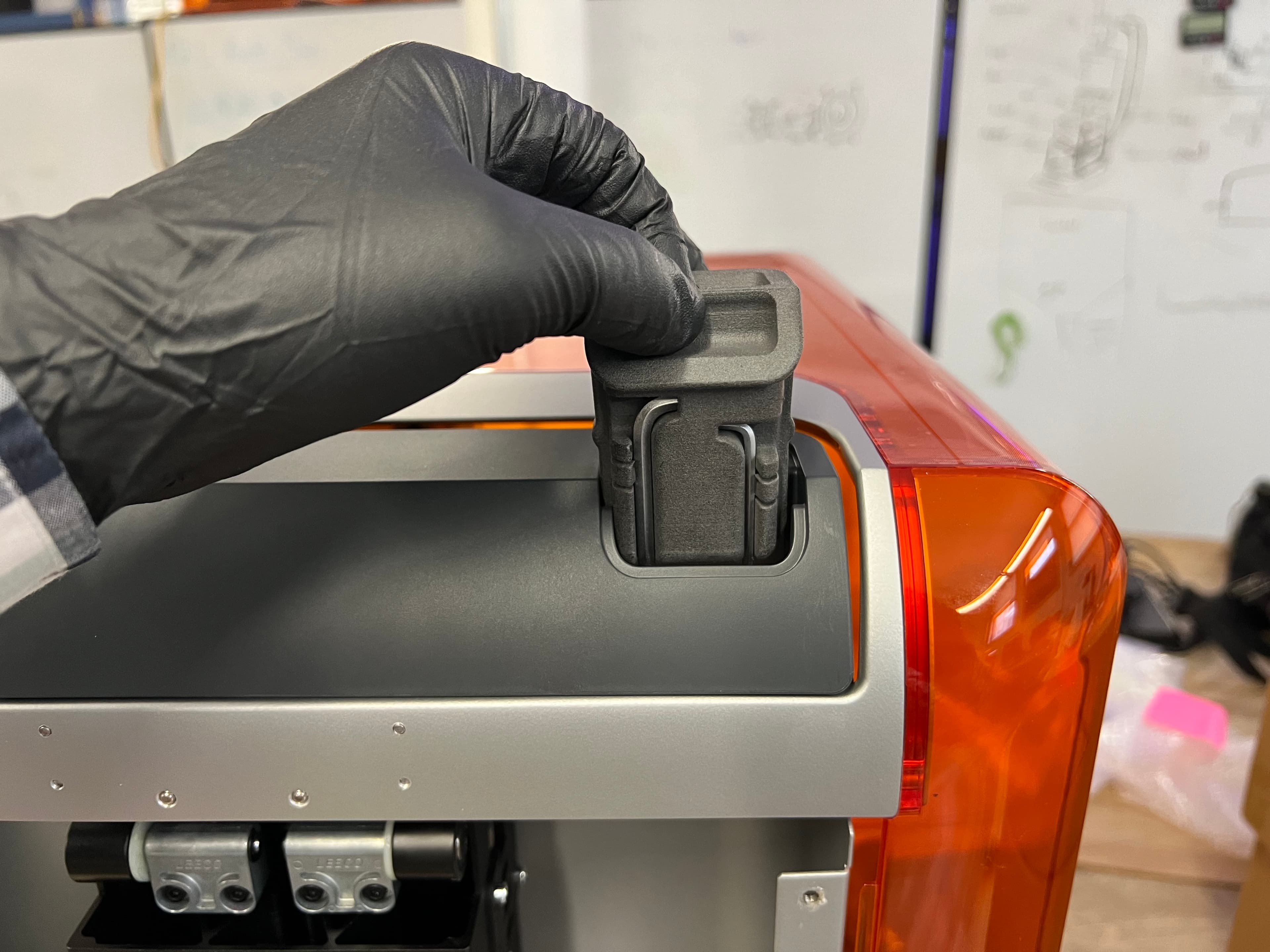
Place the tool caddy back into its slot in the tower cap.
Reinstalling the back panel
Overview: After reinstalling the tower cap, reinstall and secure the back panel.
Step 1: Close the printer cover
Close the printer cover before reinstalling the back panel.
Step 2: Mount the back panel
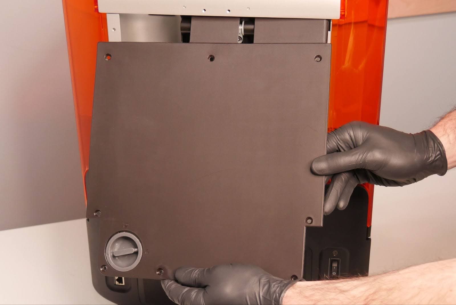
Slide the top edge of the back panel under the cover bracket. Ensure that the eight screw holes in the back panel align with the corresponding holes in the printer and the back panel sits flush with the sides of the cover.
Step 3: Secure the back panel

Thread one back panel screw into each of the eight screw holes in the back panel. Use a 2.5 mm hex driver to tighten until snug.
Finalizing the repair
Overview: After installing the new Z-axis limit switch, power on the printer and perform final checks.
Step 1: Power on the printer
Connect the power cable to the printer and the power supply. Turn on the switch at the back of the printer. The printer initializes.
Step 2: Run a test print
Insert any missing consumables and run a test print. Check that the print starts normally and the parts print successfully. Contact Formlabs Support or your authorized reseller to share the results of the procedure.