
Required Supplies:
Formlabs:
- Cover assembly
- 2.5 mm hex driver (included in the Form 4 tool caddy)
Third-party:
- Flathead screwdriver
- Nitrile gloves

The cover is the upper enclosure of a Form 4 generation printer. It is made of a strong, orange-tinted material which blocks UV light from the Backlight Unit and protects liquid resin from curing due to ambient light. Large cracks or other damage to the cover can affect print quality or allow stray UV light to escape the printer.
Use this guide to replace the cover on a Form 4 generation printer.
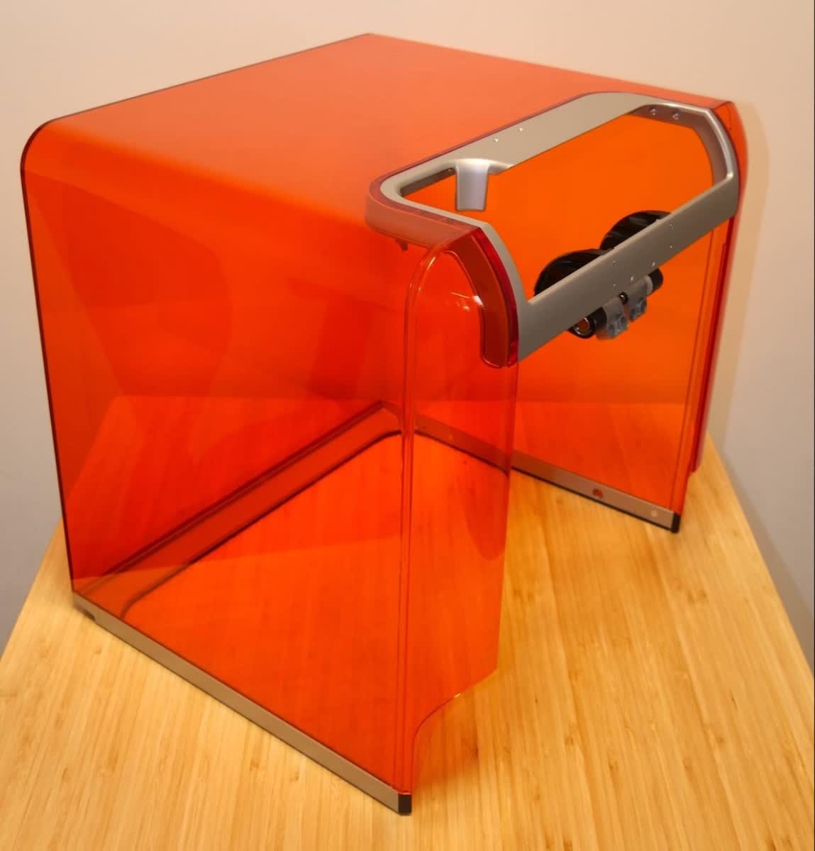
Required Supplies:
Formlabs:
Third-party:
Estimated time: 30 minutes
Preparing the workspace
Overview: Prepare the printer and a dust-free workspace for replacing the cover.
Step 1: Remove the build platform
Remove the build platform first to avoid dripping resin onto the Light Processing Unit (LPU).
Step 2: Remove the resin cartridge
Remove the resin cartridge and close the vent cap to prevent resin from dripping off of the bite valve and into the printer.
Step 3: Remove and store the resin tank and mixer
Unlatch the mixer and resin tank. Remove the resin tank and cover it with its lid. Set the tank aside on a clean, flat surface.
NOTICE:
Wear gloves and hold the resin tank by the tank grips on either side to avoid contamination or damage to the underside of the tank.
Step 4: Prepare the workspace
Clear a workspace around your printer. Ensure that the workspace is well-ventilated and free of dust. Prepare additional space for storing the back panel of the printer during maintenance.
Step 5: Clean the printer
WARNING:
Resin may cause skin irritation or an allergic skin reaction. Wear gloves when handling liquid resin or resin-coated surfaces. Wash skin with plenty of soap and water.
Open the printer cover and clean any resin pooled on and around the LPU with paper towels. Dampen the paper towels with isopropyl alcohol if necessary to fully remove the resin.
DANGER:
Fire hazard. IPA is flammable. Keep containers closed, and keep out of the reach of children.
Step 6: Unplug the printer
Disconnect the power cable before continuing with maintenance. Do not perform maintenance on the printer while it is connected to power. Wait five minutes after disconnecting the printer from power before proceeding.
DANGER:
Performing maintenance on the printer while it is plugged in increases the risk of electric shock. Never remove the back panel of the printer while the printer is plugged in. Never reconnect the printer to power while the back panel is uninstalled.
Removing the back panel
Overview: Remove the back panel to access the cover hinges.
NOTICE:
Formlabs printers contain sensitive electronic components. Ground yourself before touching any electronics in the printer by using a grounding strap or touching a grounded piece of metal.
Step 1: Remove the back panel screws
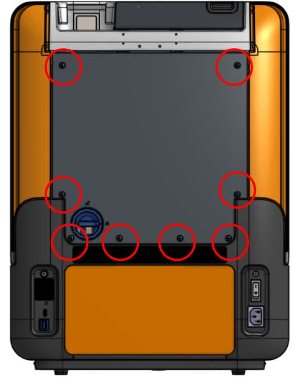
Use a 2.5 mm hex driver to remove the eight screws securing the back panel to the printer. Set the screws aside.
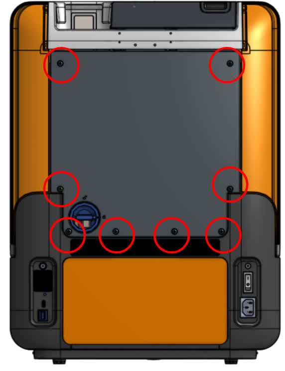
Step 2: Remove the back panel
Remove the back panel by sliding it down and away from the back of the printer. Set the back panel aside.

Removing the cover
Overview: After preparing the printer and workspace, remove the cover.
Step 1: Remove the tool caddy
If you have not done so already, remove the tool caddy from the tower cap to access the 2.5 mm hex driver provided with the printer. Set the tool caddy aside.
Step 2: Open the printer cover
Open the printer cover for easy access to the cover damper, hinges, and the underside of the tower cap.

Step 3: Remove the tower cap
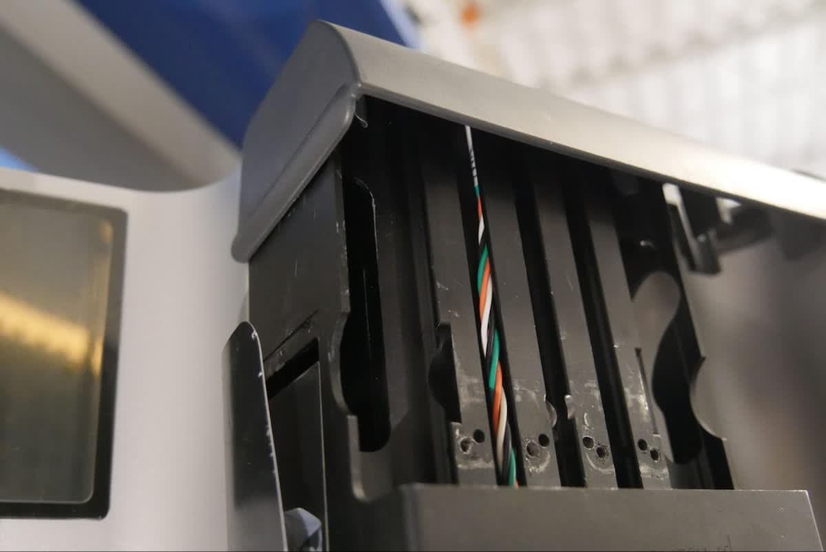
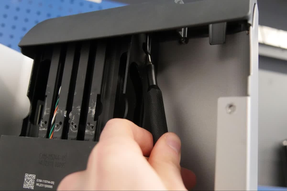
The tower cap is secured to the Z-tower via two clips, one on each side of the Z-tower. From below the tower cap, use a flathead screwdriver or other similar tool to gently pry the clips away from the Z-tower. Lift the tower cap straight up to separate it from the printer. Set the tower cap aside.


Step 4: Locate the cover damper
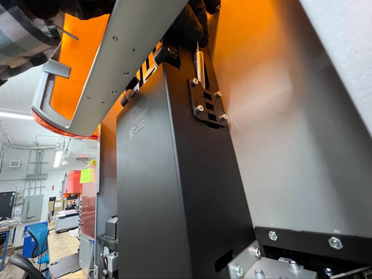
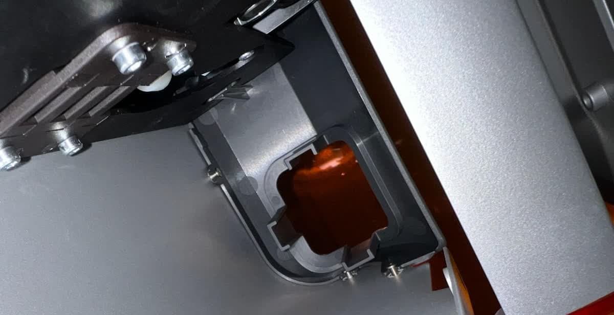
The cover damper on the Form 4 generation printer is located on the right side of the Z-tower, as seen when facing the back of the printer. It is a small piston secured behind a rectangular bracket.
Step 5: Remove the cover damper
The cover damper sits in a bracket that is secured to the Z-tower. Slide the cover damper upwards and out of its slot. Set the cover damper aside.
Step 6: Remove the cover hard stop screw
The cover's range of motion is constrained by a screw at the end of the hinge assembly that interacts with the cover damper. Using a 2.5 mm hex driver, loosen and remove the hard stop screw. Be careful not to drop the screw into the Z-tower. Set the hard stop screw aside.
Step 7: Remove the hinge screws
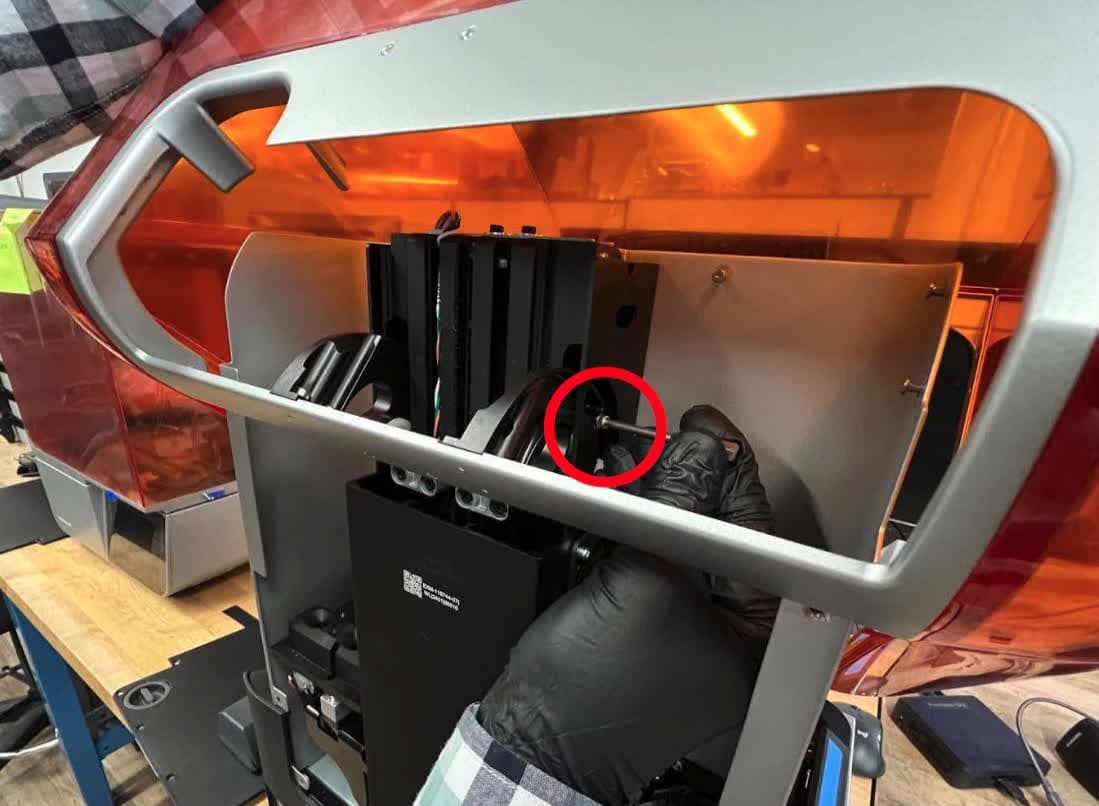
The two cover hinges are secured to the printer with two screws. Close the cover to better access these screws. Using a 2.5 mm hex driver, loosen and remove the four hinge screws. Be careful not to drop the screws into the Z-tower. Set the hinge screws aside.
Step 8: Remove the cover
Lift the cover away from the printer. Set the cover aside for disposal.
Installing the replacement cover
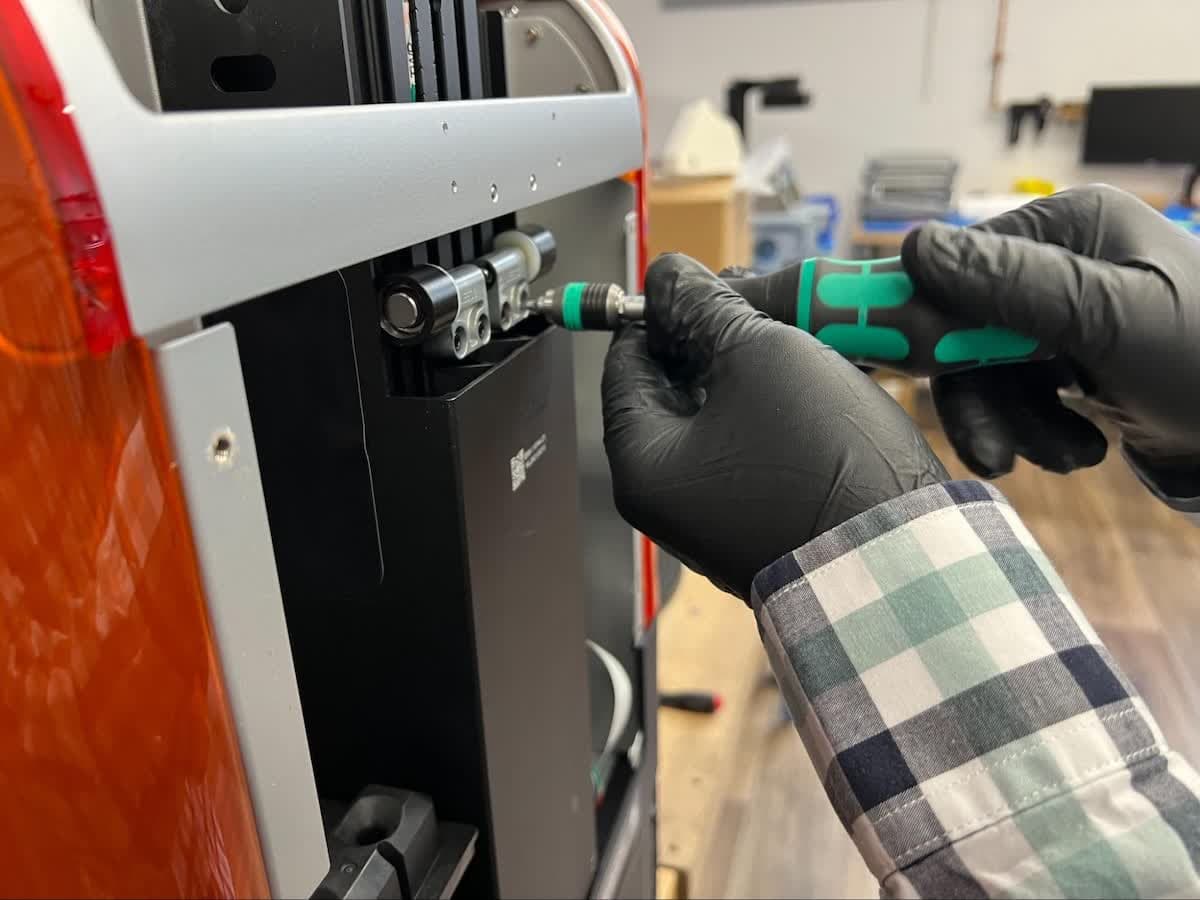
Overview: Mount and secure the replacement printer cover.
Step 1: Position the cover hinges
Place the new cover upside down on your work surface, with the hinges facing you. Rotate the hinges so they are parallel and angle slightly forward from vertical. Note that the hinges only rotate in one direction.

Step 2: Mount the cover
Carefully lower the cover onto the printer. Check that the hinges are parallel and sit flat against the Z-tower. If not, remove the cover and repeat the previous step.
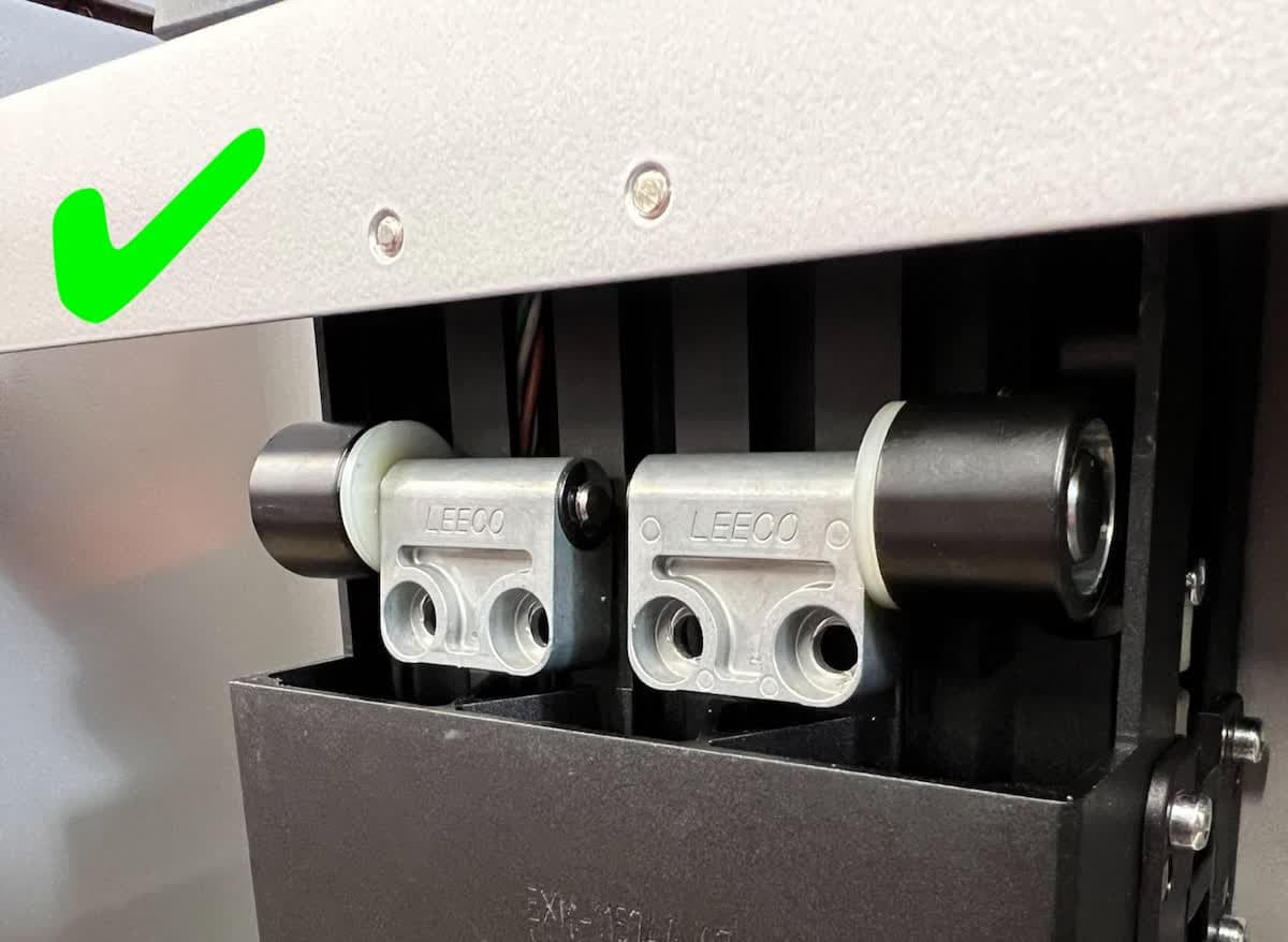

Properly-positioned cover hinges
Improperly-positioned cover hinges
Step 3: Loosely secure the cover
Thread the four cover hinge screws into the screw holes in the two cover hinges. Do not fully tighten the screws at this time.
Step 4: Shim the cover
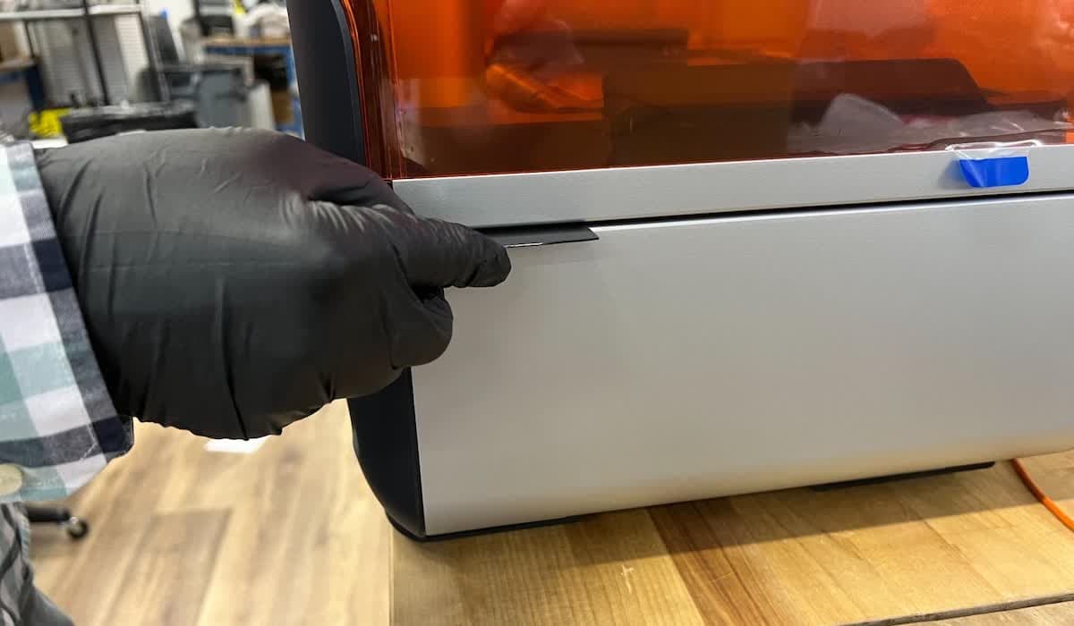

Open the tool caddy and remove eight alignment shims. Arrange the shims in two stacks of four. Lift upon the cover and insert a stack of shims under both of the rear corners of the cover.
Step 5: Adjust the cover


Properly-aligned printer cover
Improperly-aligned printer cover
Press down on the cover. While pressing on the cover, shift it left or right as needed to align the corners of the cover with the printer shells.
Step 6: Secure the cover
Using a 2.5 mm hex driver, tighten the four cover hinge screws until snug.
Step 7: Remove shims
Remove the shims and store them in the tool caddy.
Step 8: Reinstall the cover damper

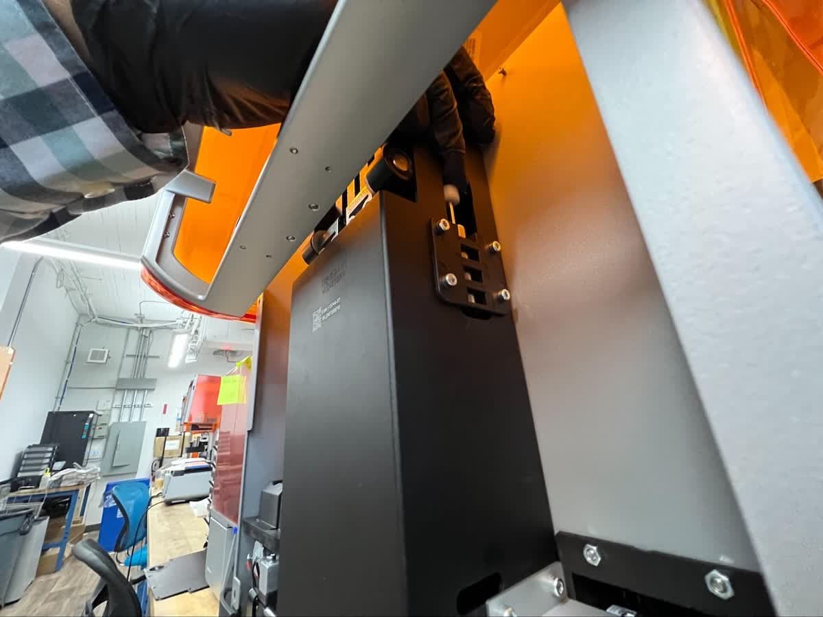
Step 10: Reinstall the cover hard stop screw
Thread the hard stop screw into its screw hole at the end of the hinge assembly above the cover damper. Using a 2.5 mm hex driver, tighten until snug.

Step 11: Align the tower cap
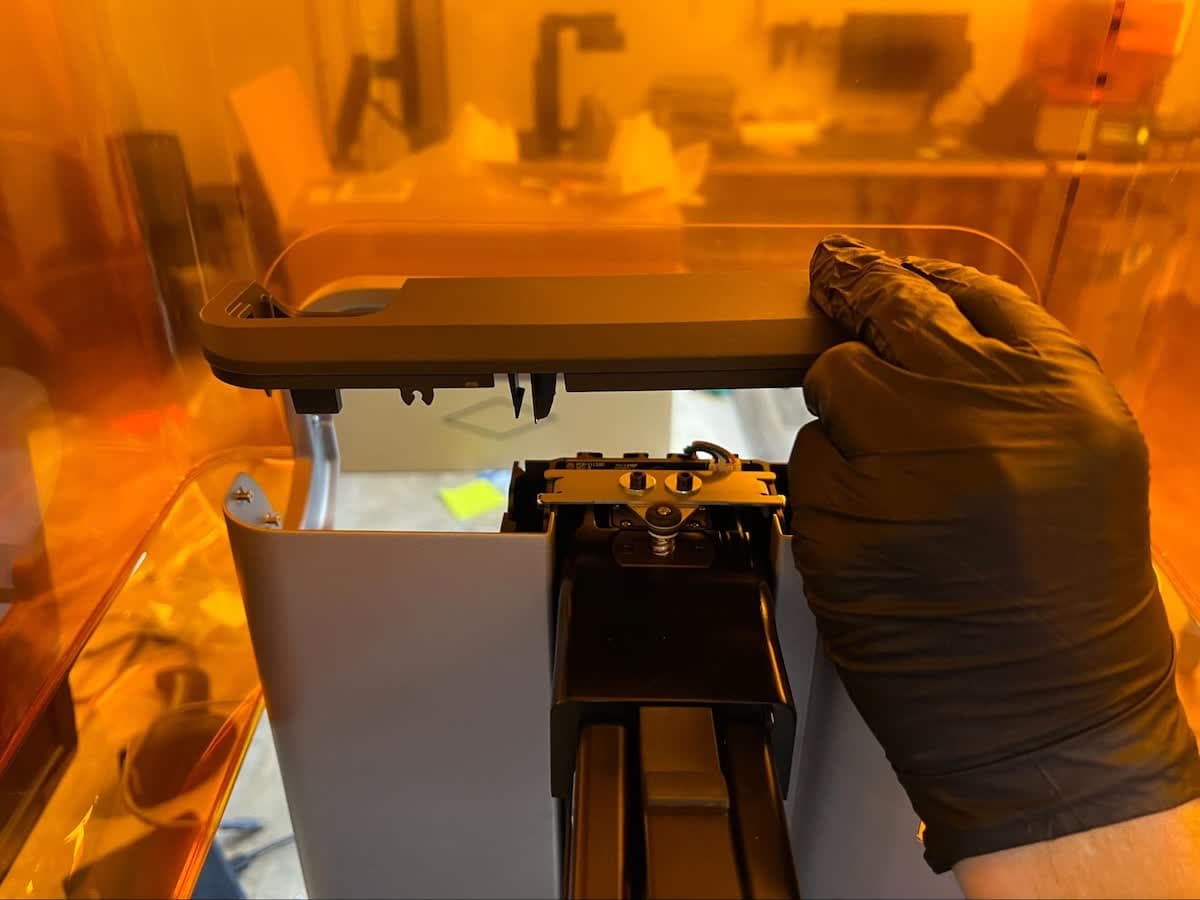
Place the tower cap on top of the Z-tower. From below, check that the clips align with the outside of the Z-tower and the retention features on the tower cap align with the pins in the printer.
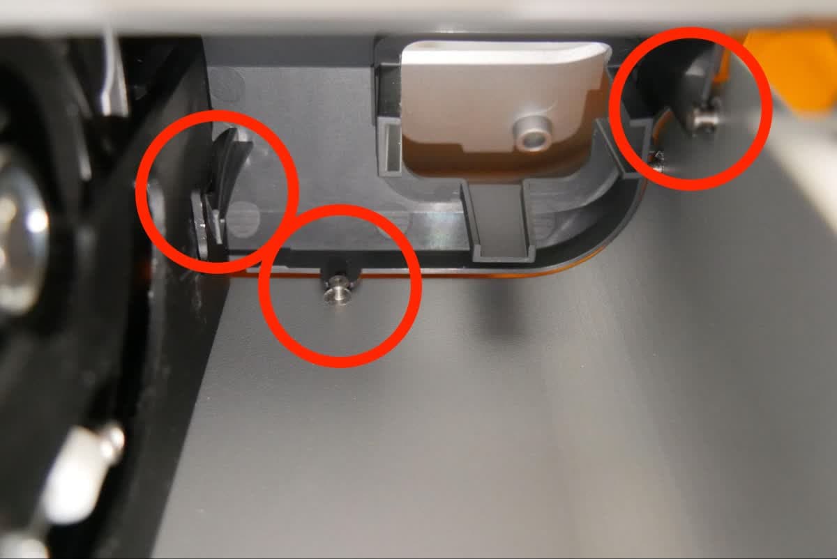
Step 12: Secure the tower cap
Press down on the tower cap to engage the clips. The tower cap sits flush against the Z-tower when properly installed.

Step 13: Replace the tool caddy
Place the tool caddy back into its slot in the tower cap.

Reinstalling the back panel
Overview: After replacing the cover, reinstall and secure the back panel.
Step 1: Close the printer cover
Close the printer cover before reinstalling the back panel.
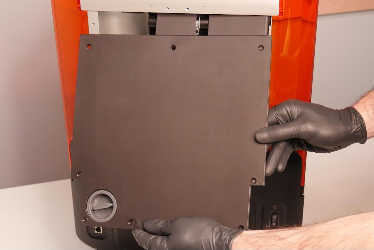
Step 2: Mount the back panel
Slide the top edge of the back panel under the cover bracket. Ensure that the eight screw holes in the back panel align with the corresponding holes in the printer and the back panel sits flush with the sides of the cover.
Step 3: Secure the back panel
Thread one back panel screw into each of the eight screw holes in the back panel. Use a 2.5 mm hex driver to tighten until snug.
Finalizing the repair
Overview: After installing the new cover, power on the printer and perform final checks.
Step 1: Power on the printer
Connect the power cable to the printer and the power supply. Turn on the switch at the back of the printer. The printer initializes.
Step 2: Test the cover
Open and close the cover several times. Check that it moves smoothly and the printer properly detects when the cover is open or closed. Contact Formlabs Support or your authorized reseller to share the results of the procedure.