
Required Supplies:
Formlabs:
- Diffuser panel
- 2.5 mm hex driver (included in the Form 4 tool caddy)
Third-party:
- Philips screwdriver
- Nitrile gloves

The diffuser panel lies sandwiched between the Backlight Unit and the Light Processing Unit (LPU) on Form 4 generation printers. It evenly distributes the light from the Backlight Unit and is necessary for a functioning optical system. A damaged diffuser panel may prevent the printer from printing properly.
Use this guide to replace the diffuser panel on a Form 4 generation printer.
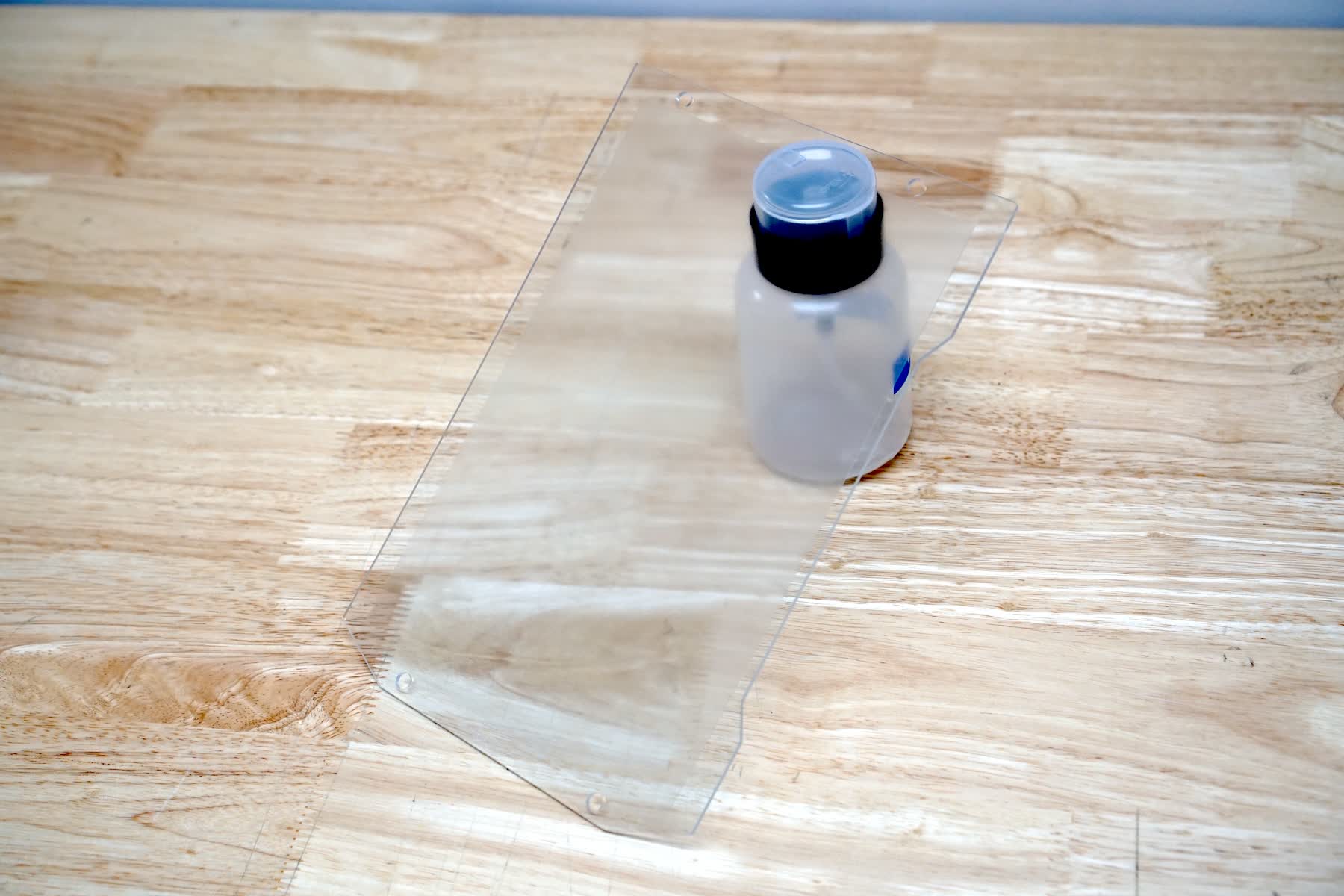
Required Supplies:
Formlabs:
Third-party:
Estimated time: 30 minutes
Preparing the workspace
Overview: Prepare the printer and a dust-free workspace for replacing the diffuser panel.
Step 1: Remove the build platform
Remove the build platform first to avoid dripping resin onto the Light Processing Unit (LPU).
Step 2: Remove the resin cartridge
Remove the resin cartridge and close the vent cap to prevent resin from dripping off of the bite valve and into the printer.
Step 3: Remove and store the resin tank and mixer
Unlatch the mixer and resin tank. Remove the resin tank and cover it with its lid. Set the tank aside on a clean, flat surface.
NOTICE:
Wear gloves and hold the resin tank by the tank grips on either side to avoid contamination or damage to the underside of the tank.
Step 4: Prepare the workspace
Clear a workspace around your printer. Ensure that the workspace is well-ventilated and free of dust.
Step 5: Clean the printer
WARNING:
Resin may cause skin irritation or an allergic skin reaction. Wear gloves when handling liquid resin or resin-coated surfaces. Wash skin with plenty of soap and water.
Open the printer cover and clean any resin pooled on and around the LPU with paper towels. Dampen the paper towels with isopropyl alcohol if necessary to fully remove the resin.
DANGER:
Fire hazard. IPA is flammable. Keep containers closed, and keep out of the reach of children.
Step 6: Unplug the printer
Disconnect the power cable before continuing with maintenance. Do not perform maintenance on the printer while it is connected to power. Wait five minutes after disconnecting the printer from power before proceeding.
DANGER:
Performing maintenance on the printer while it is plugged in increases the risk of electric shock. Never remove the back panel of the printer while the printer is plugged in. Never reconnect the printer to power while the back panel is uninstalled.
Removing the Backlight Unit
Overview: Remove the Backlight Unit to access the diffuser panel.
NOTICE:
Performing maintenance with the Backlight Unit removed increases the risk of contamination inside the optical cavity. Take care to prevent dust or debris from falling inside the printer.
Step 1: Position the printer
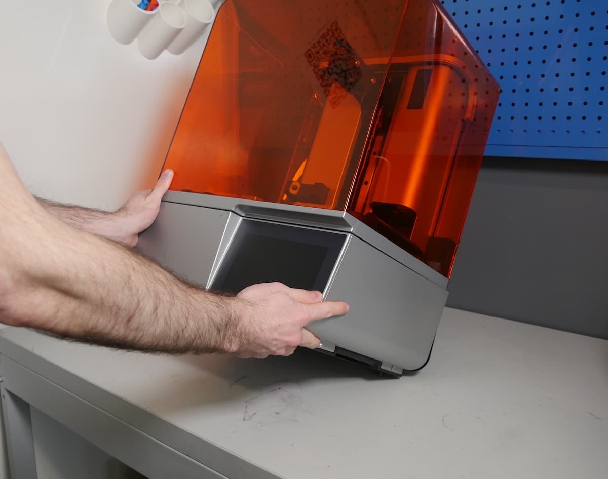
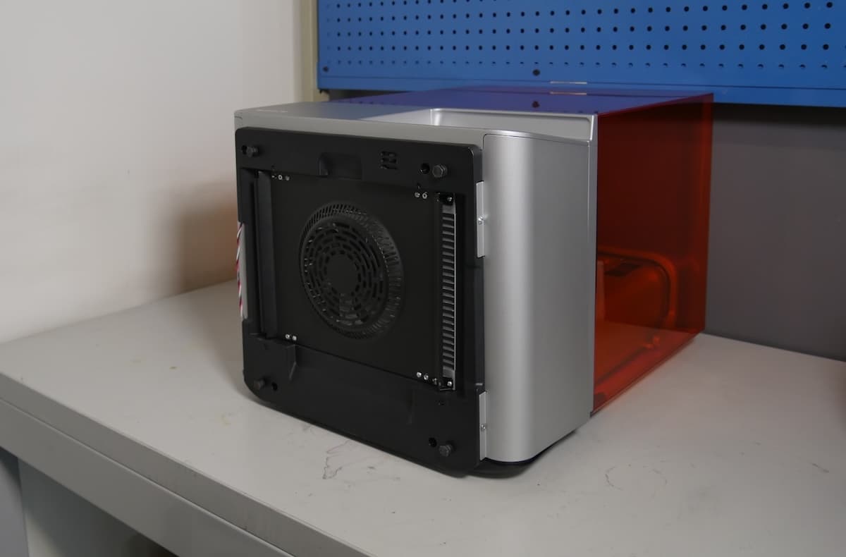
Ensure that the build platform, resin cartridge, resin tank, and mixer have been removed from the printer to prevent damage. Carefully rotate the printer so that it is resting on the back surface with the bottom facing you. Leave at least 15 cm (6 in) of clear tabletop in front of the printer when it is lying down.
Step 2: Remove the Backlight Unit screws
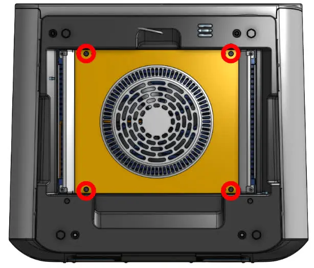
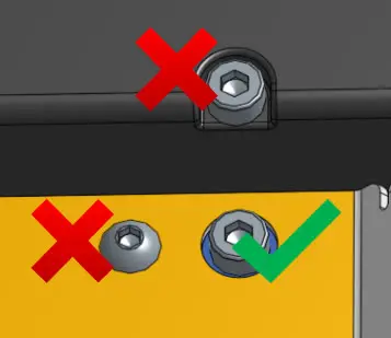
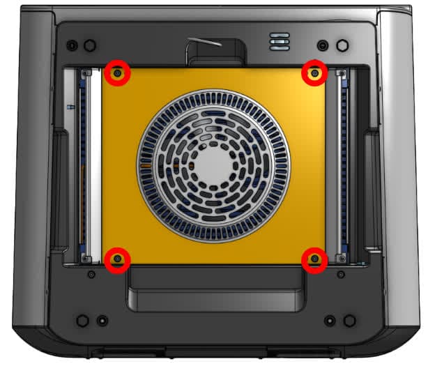
Use a 2.5 mm hex driver to remove the four socket cap screws that secure the Backlight Unit to the bottom of the printer. Do not remove the button head screws. Set the screws aside.
Step 3: Separate the Backlight Unit from the printer
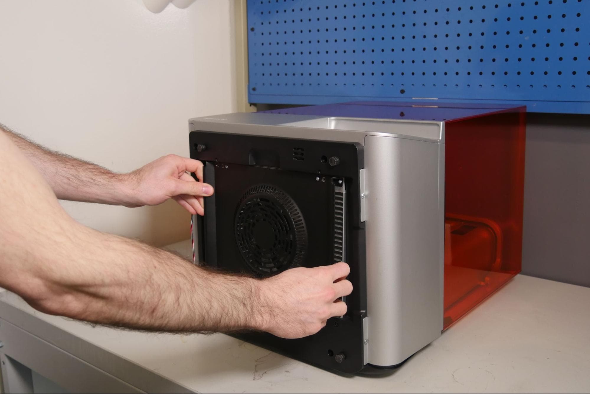
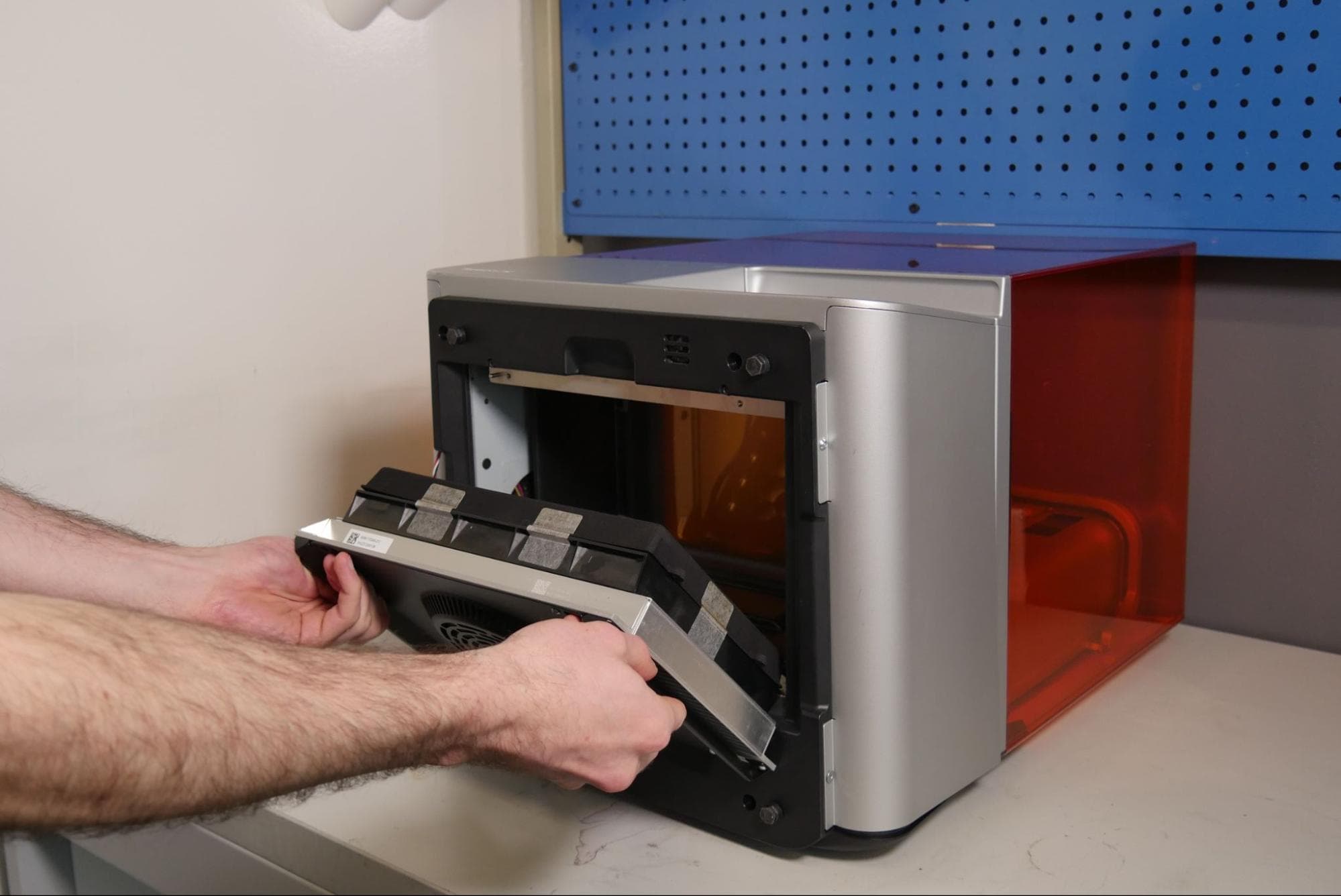
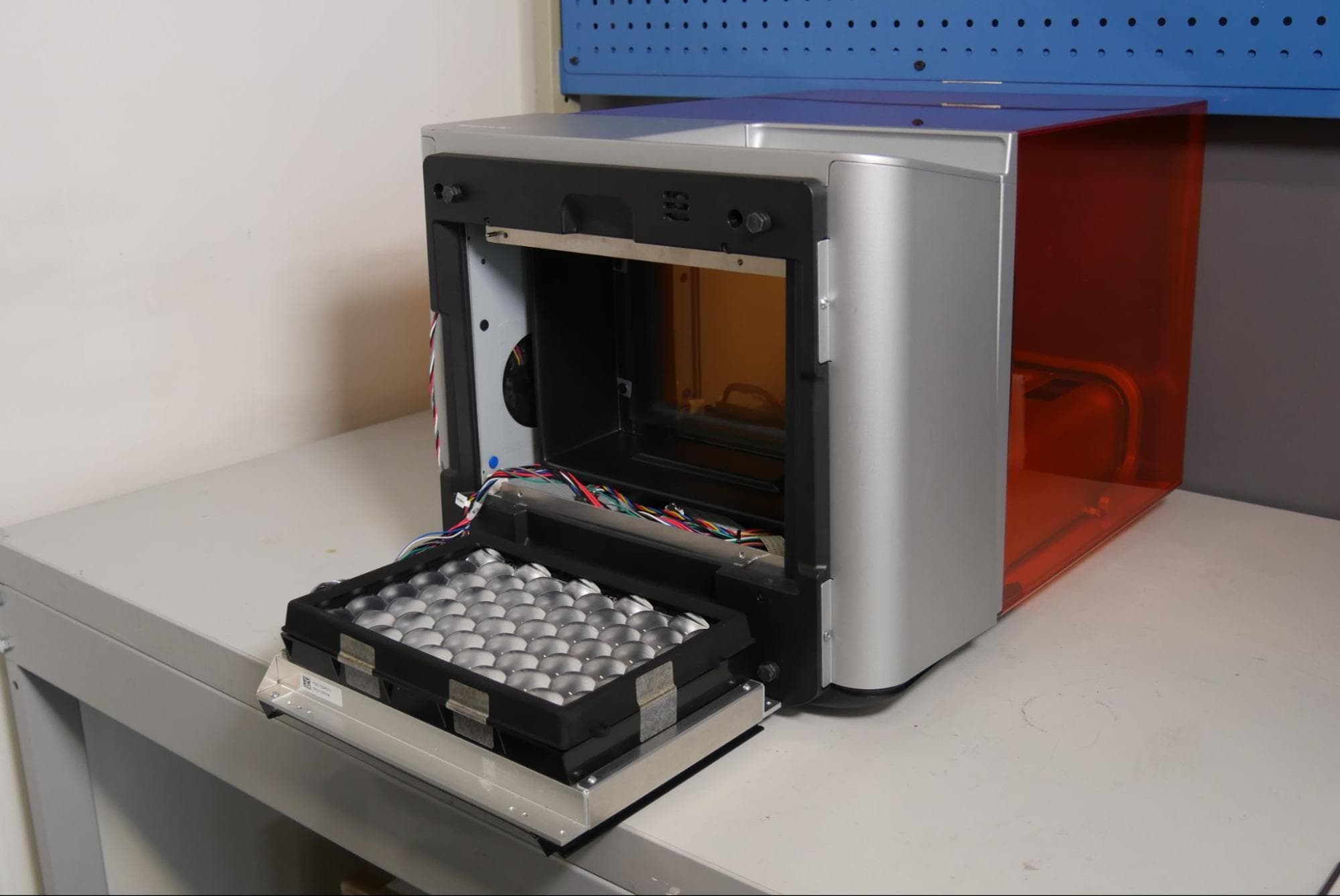
Grip the two handles on the Backlight Unit. Carefully pull the Backlight Unit away from the printer and pivot it until it rests on the work surface.
NOTICE:
Take care not to touch the components inside the exposed optical cavity.
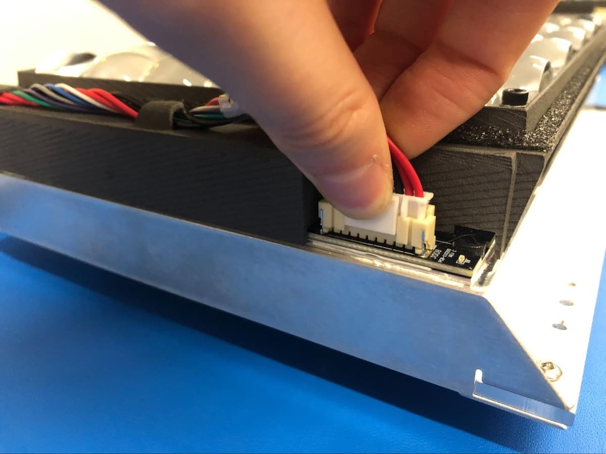
Hold the connector by its plastic housing and gently squeeze the plastic tab to unplug the backlight driver cable from the Backlight Unit. Do not pull on the individual wires.
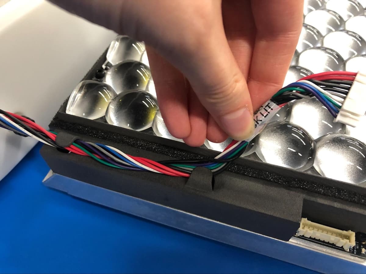
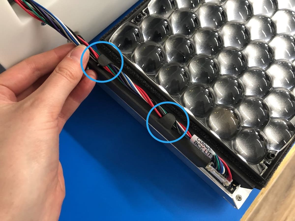
Unhook the backlight driver cable from the clips along the side of the Backlight Unit.
The LED fan cable is located in the bottom-left of the optical cavity. Squeeze the plastic retaining clip and unplug the LED fan cable from the printer. Do not pull on the wires.
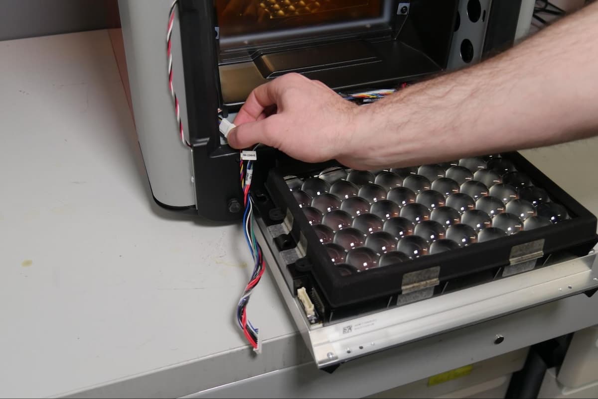
Step 7: Remove the Backlight Unit
Once all the cables are disconnected, remove the Backlight Unit from the printer. Set aside for disposal with electronic waste.
Removing the diffuser panel
Overview: After removing the Backlight Unit, remove the diffuser panel.
Step 1: Remove the diffuser panel screws
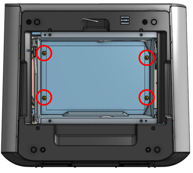
Use a Phillips head screwdriver to remove the four screws that secure the diffuser panel to the printer. Set the screws aside.
Step 2: Remove the diffuser panel
Remove the diffuser panel from the printer. Set aside for disposal.
Notice:
Take care not to touch the components inside the exposed optical cavity. Doing so may contaminate the LPU and lead to repeated print failures.
Installing the replacement diffuser panel
Overview: Mount and install the replacement diffuser panel.
Step 1: Remove protective liners from the diffuser panel
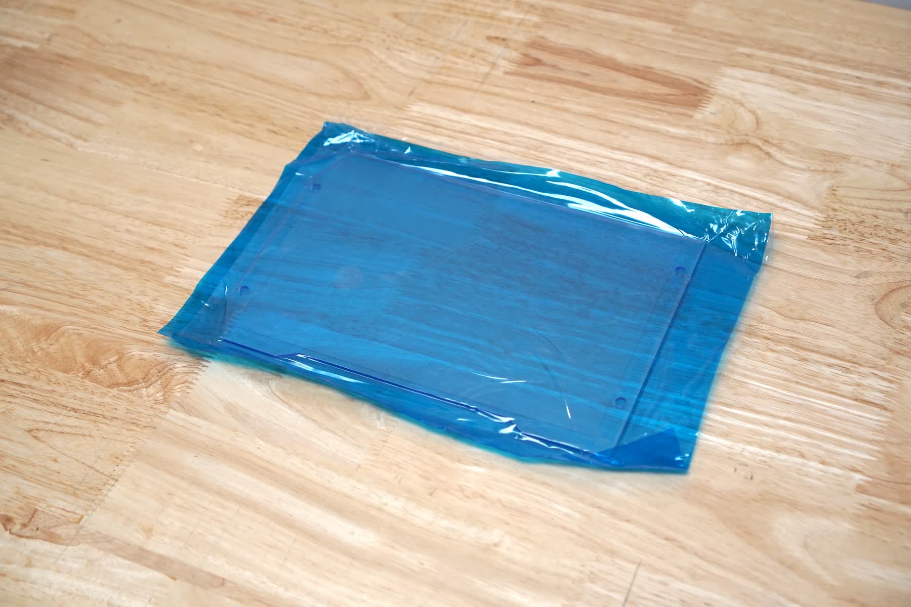
The diffuser panel ships with plastic liners to protect the part from scratches or contamination during shipping. While wearing gloves and holding the diffuser panel at the edges, remove the protective liners from both sides of the diffuser panel. Do not set the diffuser panel down once the protective liners have been removed.
Notice:
If the diffuser panel is contaminated during the repair procedure, apply a small amount of clean IPA to a lint-free cloth and wipe the surface of the diffuser panel to remove contamination or resin. Allow the diffuser panel to air dry before installing it.
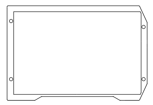
Taking care to only handle the diffuser panel at the edges, insert the replacement diffuser panel into the printer. The diffuser panel can only be installed in one orientation. Align the screw holes in the diffuser panel with the screw holes in the printer.
Step 3: Secure the replacement diffuser panel
Thread the four Phillips head screws into the screw holes. Using a Phillips head screwdriver, hand-tighten the four screws to secure the diffuser panel to the printer. Do not overtighten.
Notice:
Use care when installing the screws to avoid scratching the diffuser panel. Scratching the diffuser panel may lead to persistent print failures.
Installing the Backlight Unit
Overview: Once the replacement diffuser panel is installed, connect and reinstall the Backlight Unit.
Step 1: Position the Backlight Unit in front of the printer
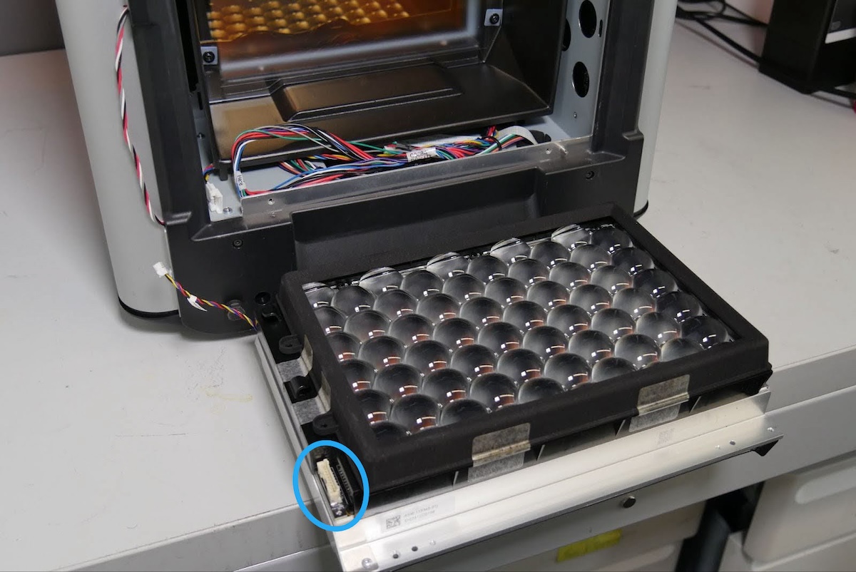
Place the Backlight Unit on the workspace in front of the printer. Orient the Backlight Unit with the backlight driver cable connected at the front-left.
NOTICE:
Do not touch the exposed lenses. Doing so may contaminate the lenses and lead to repeated print failures.
Step 2: Connect the LED fan cable
Connect the LED fan cable connector to the LED fan cable at the back of the printer. The connector makes an audible and tactile click when secured.
Connect the backlight driver cable to the Backlight Unit. The connector makes an audible and tactile click when secured.
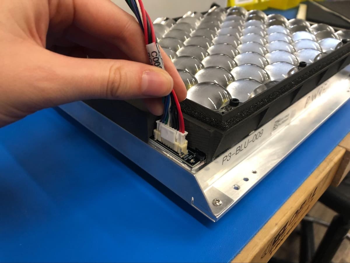
Route the cable along the edge of the Backlight Unit and push it gently under the cable clips until the cable is flush with the surface of the Backlight Unit.
Step 5: Organize cables
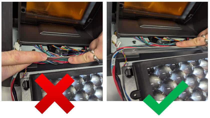
Some internal cables may have moved during the repair procedure. Move any loose cables so they are positioned alongside the metal tab in the optical cavity.
Step 6: Install the Backlight Unit
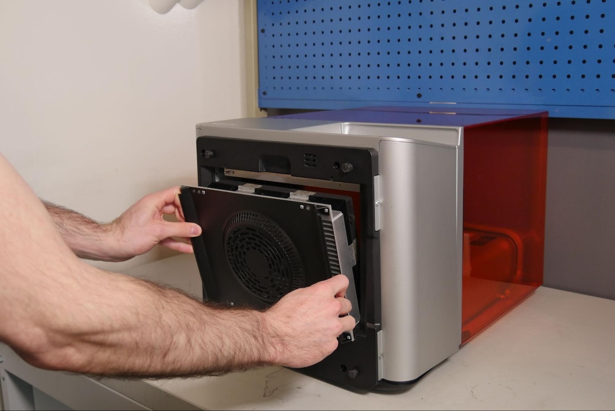
Lifting with the two handles, gently slide the Backlight Unit into the printer. Ensure the Backlight Unit is fully seated.
Notice:
Using a 2.5 mm hex driver, hand-tighten the four socket cap screws on the bottom of the printer to secure the Backlight Unit.
Finalizing the repair
Overview: After securing the Backlight Unit, power on the printer and perform final checks.
Step 1: Power on the printer
Connect the power cable to the printer and the power supply. The printer initializes.
Step 2: Run a test print
Insert any missing consumables and upload and start a print. Perform a small test print to ensure that the printer works normally. Contact Formlabs Support or your authorized reseller to share the results of the procedure.