WHITE PAPER
Formlabs Logo

Replacing the Form 4L SOM

Replacing the Form 4L SOM

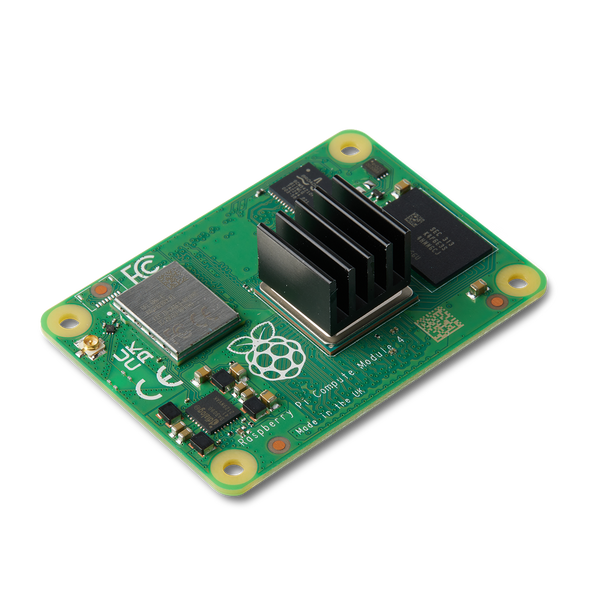
The Form 4L system on a module (SOM) plugs in to the motherboard and runs firmware on the printer. A malfunctioning SOM may cause the printer to freeze during initialization or fail to turn on.

Use this guide to replace the Form 4L SOM.

Form 4L SOM

Required Supplies:

Formlabs:

  • System on module (SOM)
  • 2 mm hex driver (included in the Form 4L tool cap assembly)
  • 2.5 mm hex driver (included in the Form 4L tool cap assembly)

Third-party:

  • ESD-safe tweezers
  • Piece of printer paper
  • Nitrile gloves
  • Anti-static grounding strap

Estimated time: 30 minutes

Danger:

Read and follow all safety instructions and warnings in the operator manual. Replacement with incorrect parts can lead to burns, shock, fire, or explosion. Dispose of all parts in accordance with local regulations.

Preparing the workspace

Overview: Prepare the Form 4L and a dust-free workspace for replacing the SOM.

Step 1: Remove the build platform

Remove the build platform first to avoid dripping resin onto the optical surfaces.

Step 2: Remove the resin cartridges

Remove the resin cartridges and close the vent caps to prevent resin from dripping off of the bite valve and into the printer.

Step 3: Remove and store the resin tank and mixer

Unlatch the mixer and resin tank. Remove the resin tank and cover it with its lid. Set the tank aside on a clean, flat surface.

Notice:

Wear gloves and hold the resin tank by the tank grips on either side to avoid contamination or damage to the underside of the tank.

Step 4: Prepare the workspace

Clear a workspace around your printer. Ensure that the workspace is well-ventilated and free of dust.

Step 5: Clean the printer cavity

Warning:

Resin may cause skin irritation or an allergic skin reaction. Wear gloves when handling liquid resin or resin-coated surfaces. Wash skin with plenty of soap and water.

Open the printer cover and clean any resin pooled on and around the LPU with paper towels. Dampen the paper towels with isopropyl alcohol if necessary to fully remove the resin.

Danger:

IPA is flammable and presents a fire hazard. Keep containers closed, and keep out of the reach of children.

Step 6: Unplug the printer

Disconnect the power cable from the printer before continuing with maintenance. Do not perform maintenance on the printer while it is connected to power. Wait five minutes after disconnecting the printer from power before proceeding.

Removing the left side panels

Overview: Remove the left side panels to access the camera.Uninstall the lower left side panel to access the motherboard.

Notice:

Formlabs printers contain sensitive electronic components. Ground yourself before touching any electronics in the machine by using an antistatic wrist band or touching a grounded piece of metal.

Step 1: Remove the lower left panel

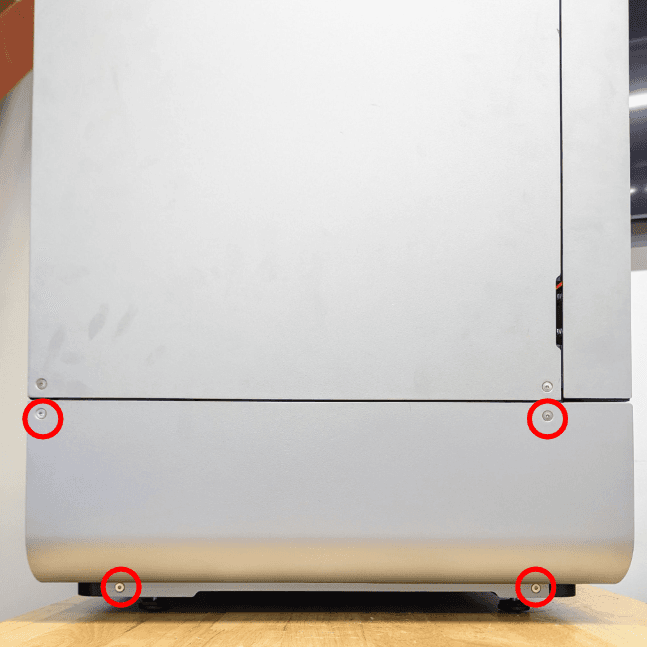
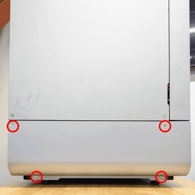
Lower left side panel screws annotated

Using a 2.5 mm hex driver, remove the four screws that secure the lower left panel to the printer.

Step 2: Remove the lower left side panel

Pull the side panel directly away from the printer. Set the panel aside.

Removing the SOM

Overview: Access the motherboard and remove the SOM.

Step 1: Ground yourself with an antistatic wrist band

Put on an antistatic wrist band, then connect it to a known ground point.

Notice:

The Form 4L motherboard and SOM are sensitive circuit assemblies and must be treated with care. Any damage from mishandling or exposure to static electricity may render the motherboard or SOM, and thus the printer, inoperable. Do not ground yourself with any surfaces that are powder-coated or painted.

Step 2: Locate the SOM

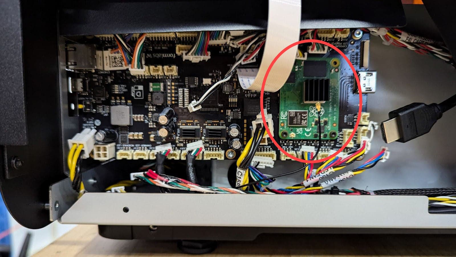
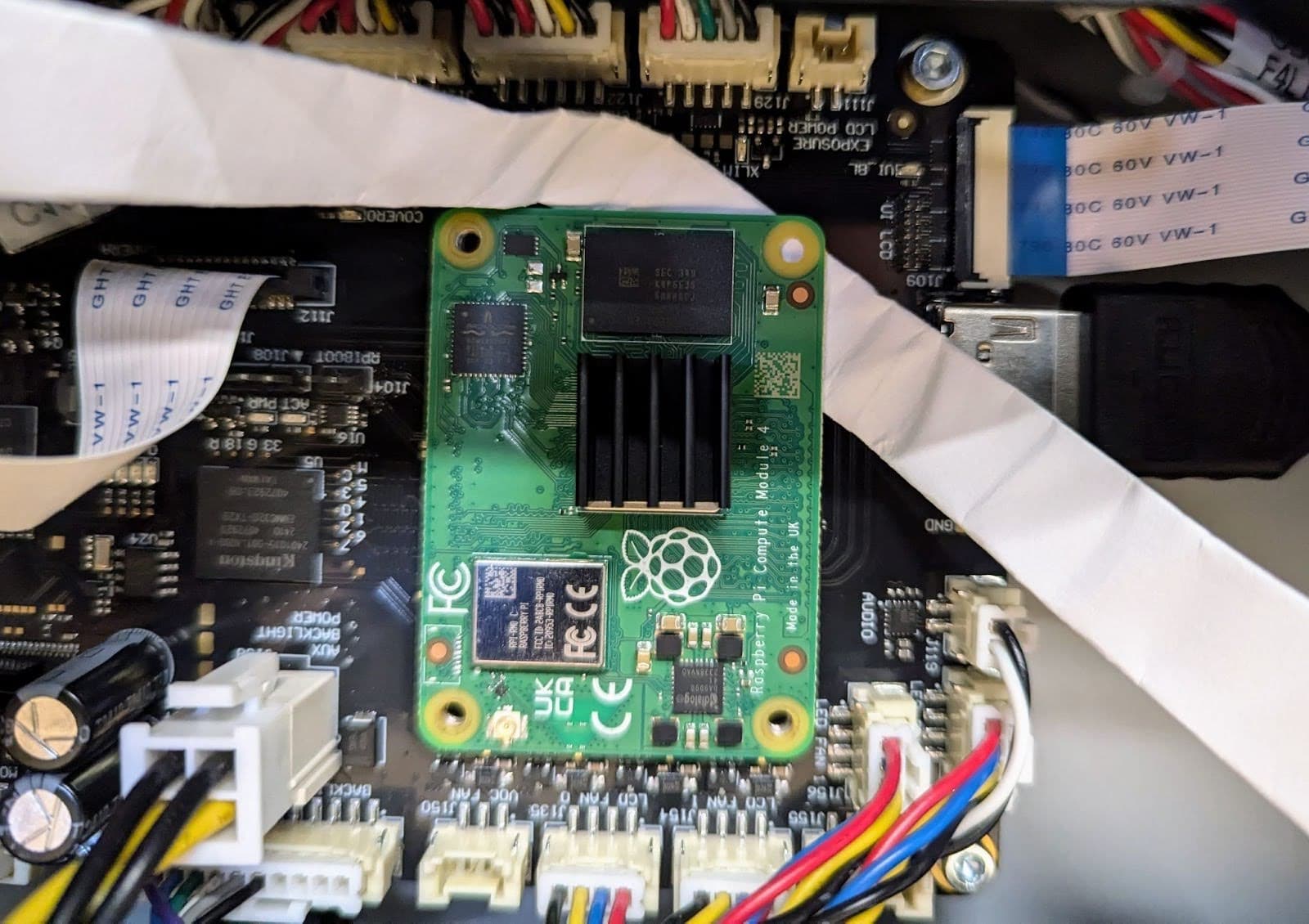
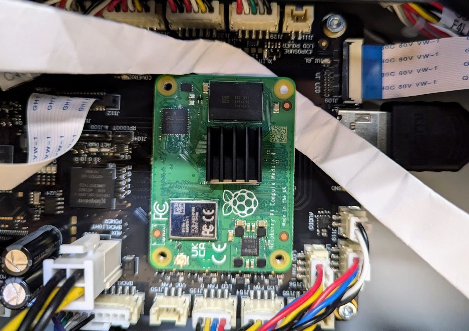
Locate the SOM

Locate the motherboard on the left side of the printer. The SOM is located on the right side of the board.

Step 3: Disconnect the Wi-FI antenna cable from the SOM

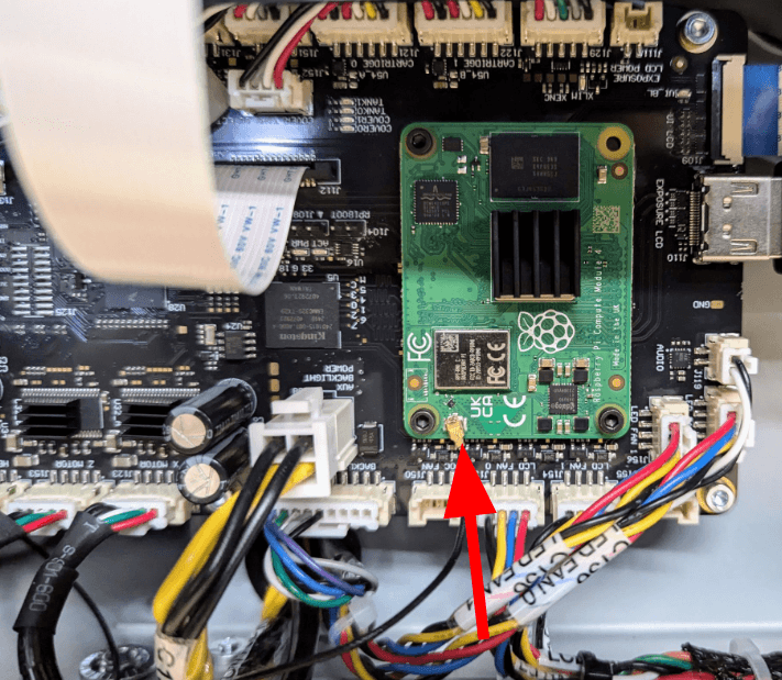
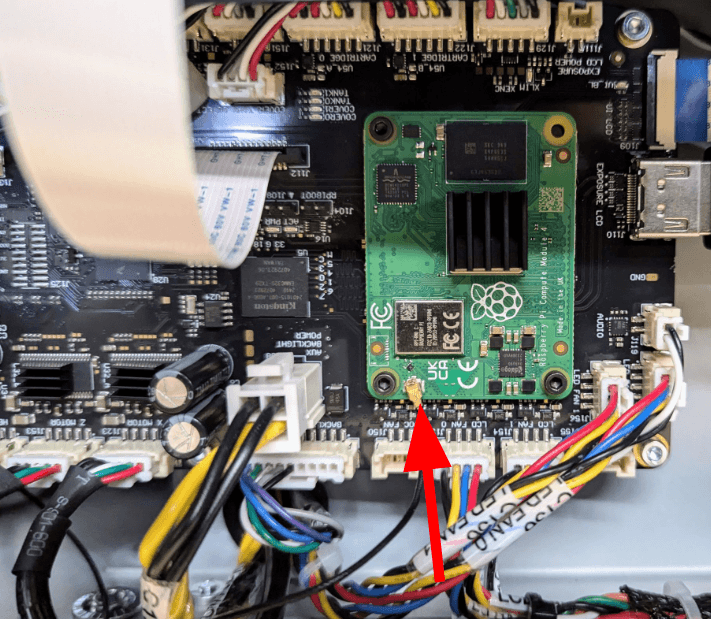
Disconnect the Wi-FI antenna cable from the SOM

Using a pair of ESD-safe tweezers, disconnect the Wi-Fi antenna cable. Take care removing the Wi-Fi antenna cable, as it is extremely fragile and may bend or break if improperly handled.

Step 4: Remove the SOM mounting screws

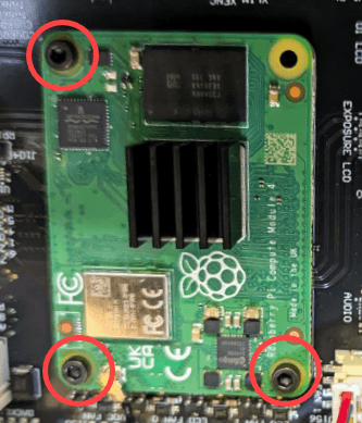
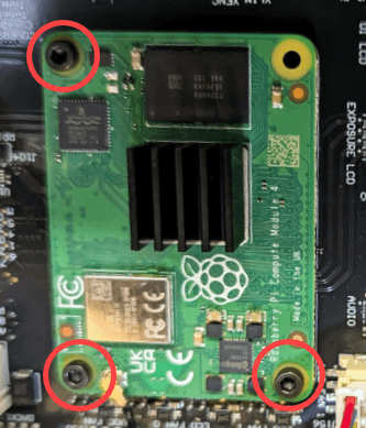
Remove the SOM mounting screws

Using a 2 mm hex driver, remove the three retention screws securing the SOM to the motherboard. Set the screws aside.

Step 5: Prepare the SOM removal tool

Prepare the SOM removal tool

The SOM is securely connected to the motherboard with two press-fit connectors. A folded piece of paper works well to assist in the removal of the SOM without damaging the motherboard. Cut an approximately 2 inch (50 mm) strip of paper. Fold the paper three times to form a 1/2 inch (12 mm) wide strip.

Step 6: Position the SOM removal tool

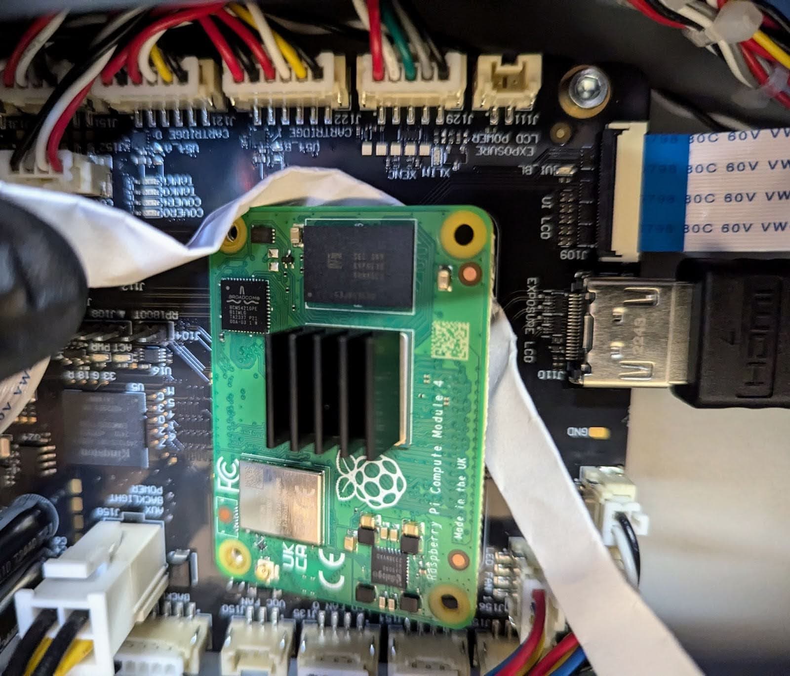
Position the SOM removal tool

Gently slide the folded paper under the upper-right corner of the SOM as shown.

Step 7: Disconnect the right side of the SOM from the motherboard

Disconnect the right side of the SOM from the motherboard

Gently pull on both sides of the paper to unseat the right side of the SOM. The right side of the SOM releases from the motherboard with steady pressure. Once the right side of the SOM has been loosened from the motherboard, set the paper strip aside.

Step 8: Remove the SOM

Grip the SOM by the top and bottom edges. Gently separate the SOM from the motherboard. Set the SOM aside for disposal with electronic waste.

Installing the replacement SOM

Overview: After removing the SOM, mount and secure the replacement SOM.

Step 1: Install the SOM

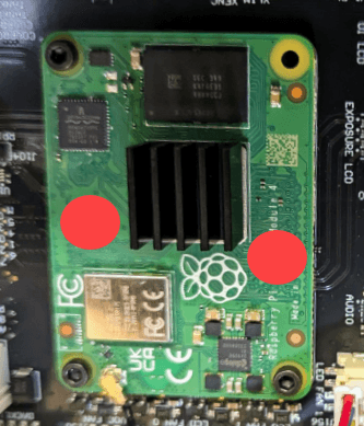
Install the SOM

Using the mounting screw holes, align the SOM with the motherboard with the Wi-Fi antenna socket at the bottom and the heatsink facing outward. Press on the left and right edges of the SOM towards the middle of the board, as annotated above, to fully seat it in the motherboard connectors.

Step 2: Secure the SOM to the motherboard

Secure the SOM to the motherboard

Using a 2 mm hex driver, screw in the three retention screws until finger tight.

Step 3: Connect the Wi-Fi antenna cable

Connect the Wi-Fi antenna cable

Align the connector housing on the end of the antenna cable over the socket on the SOM. Using a finger or the tip of a small flat-head screwdriver, push gently to seat the antenna cable.

Reinstalling the lower left side panel

Overview: Reinstall and secure the lower left side panel.

Step 1: Mount the lower left side panel

Place the lower left side panel on the printer. Ensure that the screw holes in the panel align with those in the printer frame and that it sits flush with the touchscreen assembly and the back of the machine.

Step 2: Install the lower left side panel screws

Install the lower left side panel screws

Finalizing the procedure

Overview: After replacing the SOM, power on the printer and perform final checks.

Step 1: Power on the printer

Close the printer cover and connect the power cable to the printer and the power supply. The printer initializes and displays a series of onboarding steps on the touchscreen. Follow these steps to prepare the printer for use.

Step 2: Update the printer's firmware

Update the printer's firmware. Run a test print to ensure that the printer operates normally. Contact Formlabs Support or your authorized reseller to share the results of the procedure.