
Required Supplies:
Formlabs:
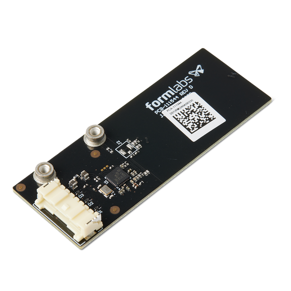
- Resin cartridge RFID board
- 2 mm hex driver (included in the Form 4L tool cap assembly)
- 2.5 mm hex driver (included in the Form 4L tool cap assembly)
Third-party:
- Nitrile gloves

On Form 4L generation printers, the resin cartridge RFID boards read resin type and volume information from the resin cartridge. A malfunctioning resin cartridge RFID board may prevent the printer from printing properly.
Use this guide to replace one or both Form 4L resin cartridge RFID boards.
Required Supplies:
Formlabs:
Third-party:
Estimated time: 30 minutes
Preparing the workspace
Overview: Prepare the Form 4L and a dust-free workspace for replacing the Form 4L resin cartridge RFID boards.
Step 1: Remove the build platform
Remove the build platform first to avoid dripping resin onto the optical surfaces.
Step 2: Remove the resin cartridges
Remove the resin cartridges and close the vent caps to prevent resin from dripping off of the bite valve and into the printer.
Step 3: Remove and store the resin tank and mixer
Unlatch the mixer and resin tank. Remove the resin tank and cover it with its lid. Set the tank aside on a clean, flat surface.
Notice:
Wear gloves and hold the resin tank by the tank grips on either side to avoid contamination or damage to the underside of the tank.
Step 4: Prepare the workspace
Clear a workspace around your printer. Ensure that the workspace is well-ventilated and free of dust. You will need to access the right side of the printer during maintenance, so rotate the printer or prepare at least 61 cm (24 in) of additional space to the right of the machine.

Step 5: Clean the printer cavity
Warning:
Resin may cause skin irritation or an allergic skin reaction. Wear gloves when handling liquid resin or resin-coated surfaces. Wash skin with plenty of soap and water.
Open the printer cover and clean any resin pooled on and around the LPU with paper towels. Dampen the paper towels with isopropyl alcohol if necessary to fully remove the resin.
Danger:
IPA is flammable and presents a fire hazard. Keep containers closed, and keep out of the reach of children.
Step 6: Unplug the printer
Disconnect the power cable from the printer before continuing with maintenance. Do not perform maintenance on the printer while it is connected to power. Wait five minutes after disconnecting the printer from power before proceeding.
Removing the side panels
Overview: Remove the right side panels to access the cartridge floor.
Notice:
Formlabs printers contain sensitive electronic components. Ground yourself before touching any electronics in the printer by using a grounding strap or touching a grounded piece of metal.
Step 1: Remove the mesh filter

Remove the mesh filter from the right side of the printer. Set the filter aside.
Step 2: Remove the lower right panel
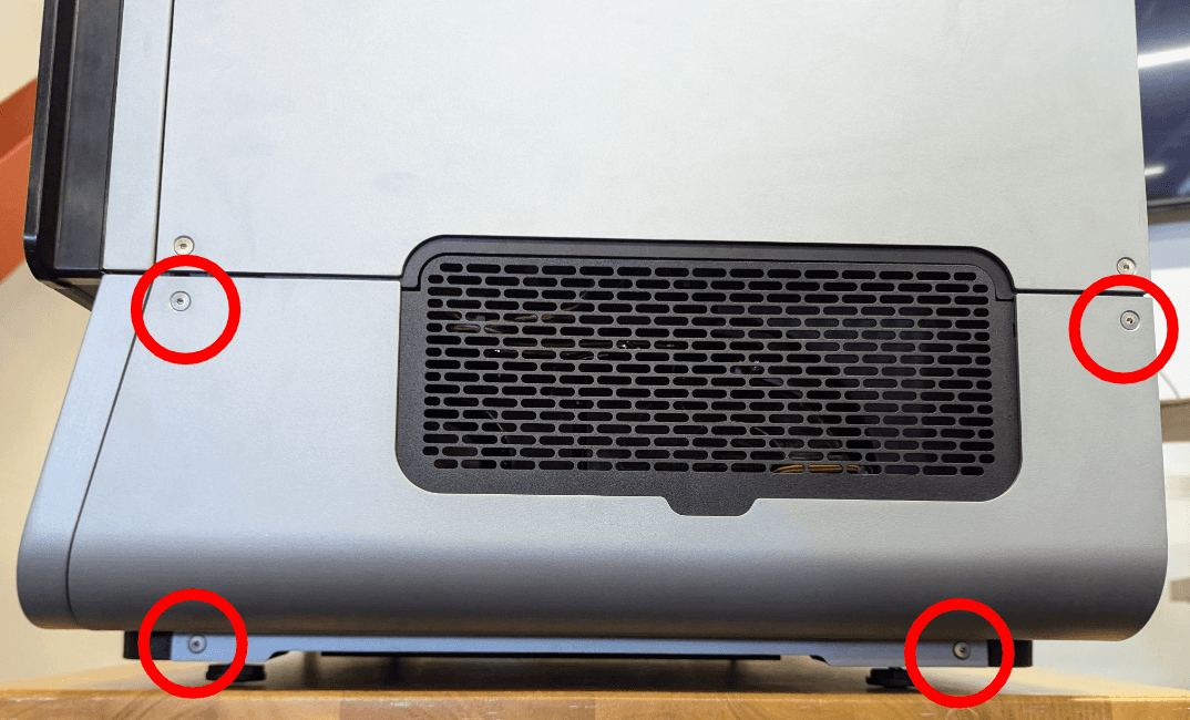
Use a 2.5 mm hex driver to remove the four screws securing the lower right panel to the printer. Remove the screws and the panel and set them aside.
Step 3: Remove the LPU fan filter

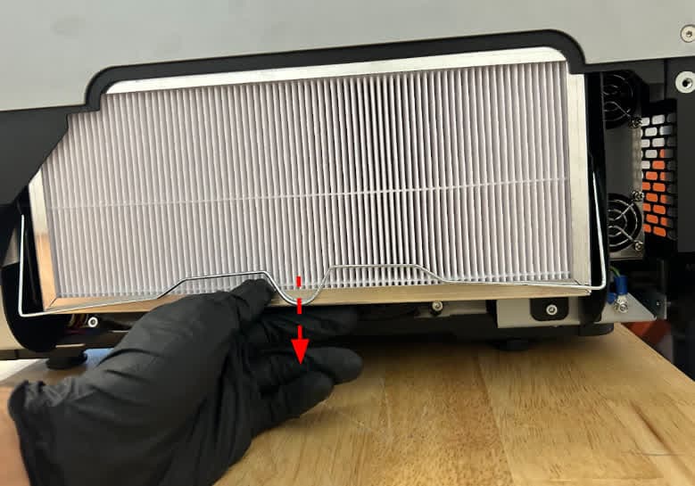
Disengage the fan retainer by pulling downwards and swinging the wire arm towards you. Remove the LPU fan filter by pulling straight down on the filter’s body. Set the filter aside.
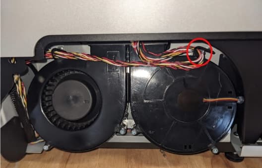
The dispense cable harness is held in place with bendable cable ties. Bend the right-hand cable tie to unhook the harness to allow more slack for the replacement process.
Step 5: Remove the upper right panel screws

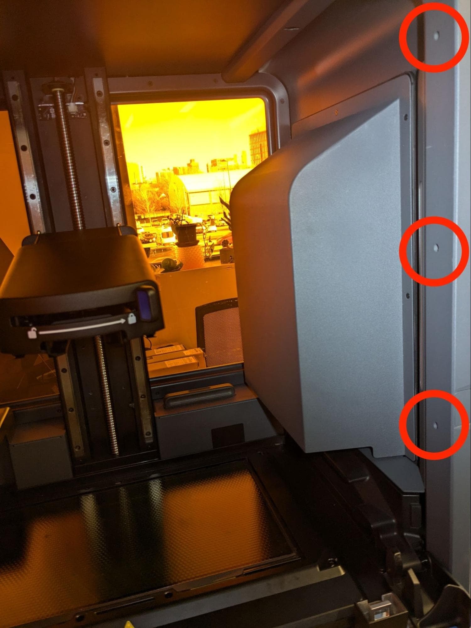
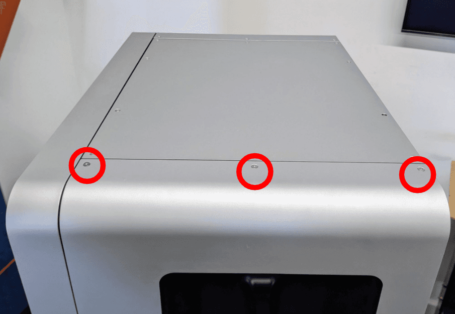
Use a 2.5 mm hex driver to remove the eight screws securing the upper right panel to the printer: three screws on the top of the panel, two screws on the bottom of the panel, and three on the front edge of the panel inside the printer.
Step 6: Separate the upper right panel from the printer


With the help of a second person, push the upper right panel straight up to release the studs on the panel from the slots in the printer frame. Carefully rotate the top of the panel down and away from the printer.
Notice:
The panel is still connected to the printer via the cartridge floor cables at this time, so support the panel to avoid straining or damaging the cables.
Step 7: Disconnect the cartridge floor cables


While continuing to support the upper right panel, unplug all the connectors to fully separate the upper right panel from the printer, then lay the panel flat. Gently squeeze the plastic tabs to unplug the cables. Do not pull on the individual wires. For reference, both cartridge floors have a cable for the dispense motor (with two wires) and the load cell (with three wires). There are also two cables for the cartridge RFID boards. For your reference, the panel is labeled F and R for the front and rear cartridge slots, respectively. Similarly, the front cartridge floor wires are labeled 0 and the rear cartridge floor wires are labeled 1.
Removing the resin cartridge RFID board
Overview: Remove the resin cartridge RFID boards.
Step 1: Remove the cartridge cavity assembly screws

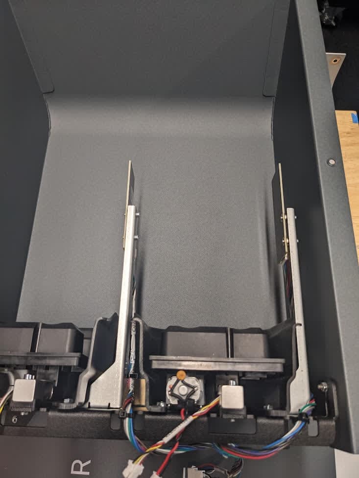
Use a 2 mm hex driver to loosen and remove the seven screws that secure the cartridge cavity assembly to the printer. Set the screws aside. Remove the cartridge cavity assembly and flip it over to access the RFID boards. Note that there is a black cover under the cavity—do not flip that over with the assembly.
Step 2: Remove the RFID mount retaining screws (right-hand RFID board only)
Each resin cartridge RFID board is attached to a RFID mount secured to the bottom bracket of the cartridge cavity assembly. If you are replacing the right-hand RFID board, use a 2 mm hex driver to remove the two mount retaining screws. Set the screws aside.

Step 3: Remove the resin cartridge RFID board retention screws

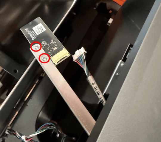
Use a 2 mm hex driver to remove the two retention screws securing the resin cartridge RFID board you are replacing to the RFID mount. If you are replacing the right-hand RFID board, tilt the mount up as shown to access the screws. Set the screws aside.
Step 4: Disconnect the resin cartridge RFID cable
Squeeze the plastic retaining clip and unplug the resin cartridge RFID cable from the board. Do not pull on the wires.
Step 5: Remove the resin cartridge RFID board
Once the cable is unplugged, the resin cartridge RFID board is separated from the printer. Set the RFID board aside for disposal with electronics waste.
Step 6: Remove the second resin cartridge RFID board
If replacing both boards, repeat steps 3–5 for the second resin cartridge RFID board.
Installing the replacement resin cartridge RFID board
Overview: Mount and secure the replacement resin cartridge RFID boards.
Step 1: Connect the resin cartridge RFID cable
Connect the resin cartridge RFID cable to the replacement RFID board. The connector makes an audible and tactile click when secured.
Step 2: Mount and secure the replacement resin cartridge RFID board

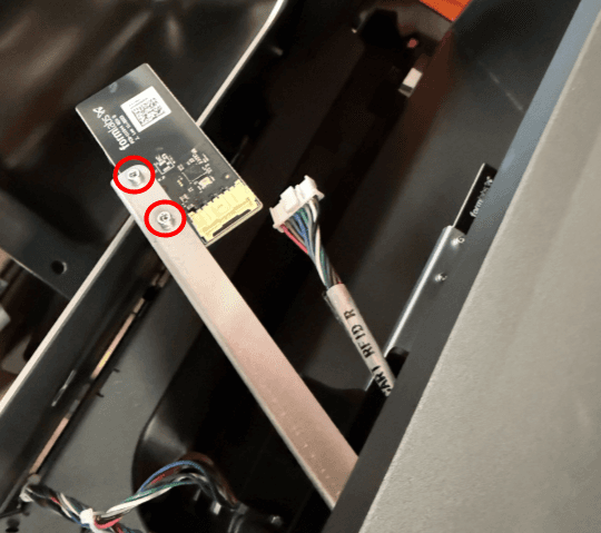
Align the replacement resin cartridge RFID board with the screw holes in the RFID mount. Ensure the board sits behind the bracket tab. Press on the far side of the RFID board with a finger to pivot the threaded side of the board against the screw holes.
Thread the resin cartridge RFID board retention screws into the screw holes. Use a 2 mm hex driver to tighten the two screws until finger tight.
If you are replacing the right-hand RFID board, use a 2 mm hex driver to secure the two RFID mount retaining screws.
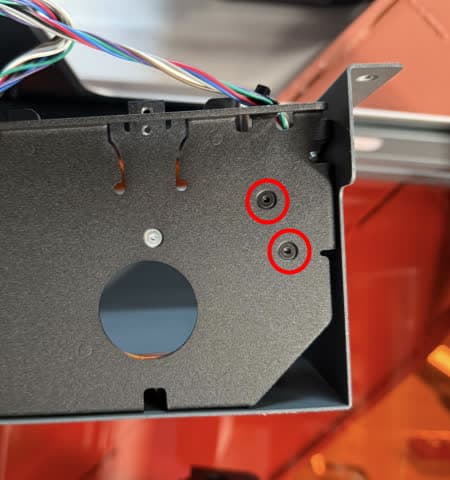
Step 4: Secure the second replacement resin cartridge RFID board
If you are replacing both boards, repeat steps 1–3 for the second replacement resin cartridge RFID board.
Step 5: Position the cartridge cavity assembly
Flip the cartridge cavity assembly into its original position and align its screw holes with their respective screw holes on the printer. Note the black cover that goes in between the assembly and the panel.
Step 6: Secure the cartridge cavity assembly
Thread one cartridge cavity assembly screw into each of the seven screw holes in the printer frame. Use a 2 mm hex driver to tighten until snug.

Reinstalling the side panels
Overview: Reinstall and secure the right side panels.
Step 1: Connect the cartridge floor cables


With the help of a second person, position the upper right panel next to the ride side of the printer. While supporting the panel, connect the cables. Make sure to connect the cables correctly according to the labeled stickers. As noted above, both cartridge floors have a cable for the dispense motor (with two wires) and the load cell (with three wires). There are also two cables for the cartridge RFID boards. For your reference, the panel is labeled F and R for the front and rear cartridge slots, respectively. Similarly, the front cartridge floor wires are labeled 0 and the rear cartridge floor wires are labeled 1.
Step 2: Mount the upper right panel

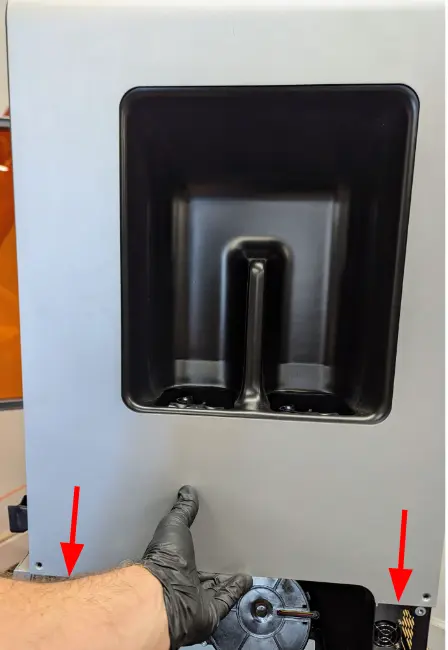
Once all cables are connected, rotate the panel upwards until it rests against the side of the printer. Check that the studs on the panel are aligned with the key slots in the printer frame, then slide the panel straight down. Ensure that the eight screw holes in the panel align with the corresponding holes in the printer.
Step 3: Secure the upper right panel


Thread one mounting screw into each of the eight screw holes in the upper right panel. Use a 2.5 mm hex driver to tighten until snug.
Bend the right cable tie to secure the dispense cable harness.

Step 5: Install the LPU fan filter


Slide the fan filter under the wire filter retainer and push upwards until fully seated. Pull downwards on the filter retainer and swing it beneath the filter to secure the filter in place.
Step 6: Mount and secure the lower right panel

Align the screw holes in the lower right panel with those in the printer frame. Thread one mounting screw into each of the four screw holes. Use a 2.5 mm hex driver to tighten until snug.
Step 7: Reinstall the mesh filter

Place the mesh filter over the grate on the right side of the printer.
Finalizing the repair
Overview: After installing the new resin cartridge RFID boards, power on the printer and perform final checks.
Step 1: Power on the printer
Connect the power cable to the printer and the power supply. The printer initializes.
Step 2: Test the resin cartridge RFID boards
Insert a resin cartridge and check that the printer recognizes it properly. Insert a second resin cartridge into the second slot and check that the printer recognized it properly. Contact Formlabs Support or your authorized reseller to share the results of the procedure.