
Required supplies:
Formlabs:
- Replacement heater control board (RP-FS1-PORO-02)
Third-party:
- 2.5 mm hex driver (flat-end)
- 3 mm hex driver (flat-end)
- Computer with PreForm
- USB A to B cable
- Antistatic wrist band

On Fuse 1 generation printers, the heater control board (also known as the Post Rock board) controls the various heaters in the printer. A faulty or malfunctioning heater control board will prevent the printer from working properly.
Use this guide to replace the heater control board on a Fuse 1 generation printer.
Required supplies:
Formlabs:
Third-party:
Estimated time: 15–30 minutes
Danger:
Read and follow all safety instructions and warnings in the operator manual. Replacement with incorrect parts can lead to burns, shock, fire, or explosion. Dispose of all parts in accordance with local regulations.
Preparing the workspace
Overview: Prepare the printer and a dust-free workspace for replacing the heater control board.
Notice:
Fuse 1 generation printers contain sensitive electronic components. Ground yourself before touching any electronics in the printer by using a grounding strap or touching a grounded piece of metal.
Step 1: Prepare the workspace
Clear a workspace around your printer. Ensure that the workspace is well-ventilated and free of dust.
Step 2: Unplug the printer
Disconnect the power cable before continuing with maintenance. Do not perform maintenance on the printer while it is connected to power. Wait five minutes after disconnecting the printer from power before proceeding.
Danger:
Performing maintenance on the printer while it is plugged in increases the risk of electric shock. Never remove the back panel of the printer while the printer is plugged in. Never reconnect the printer to power while the back panel is uninstalled.
Step 3: Remove the Wi-Fi antenna
Unscrew and remove the Wi-Fi antenna, if it is connected.
Step 4: Disconnect the nitrogen source (Fuse 1+ 30W only)
Disconnect the nitrogen hose from the quick-disconnect fitting, if connected.
Removing the lower rear panel
Overview: Remove the lower rear panel to access the interior of the printer.
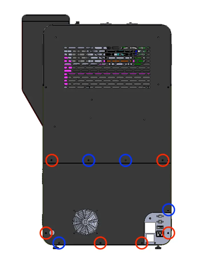
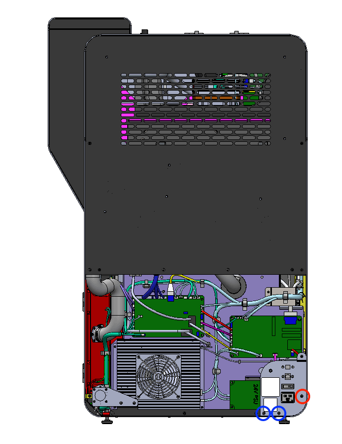
The six black lower rear panel screws are circled in red. The four chrome lower rear panel grounding screws are circled in blue.
Using a 2.5 mm hex driver, remove the six black panel screws and the four chrome panel grounding screws securing the lower rear panel to the printer. Set the screws aside, taking care to separate the black and chrome screws for later reinstallation.
Pull the lower rear panel straight back and away from the printer. Lay it down on a flat, clean surface.
Using a 2.5 mm hex driver, remove the one black and two chrome 8 mm M4 button screws securing the I/O bulkhead panel to the printer.
To avoid damaging the Wi-Fi coaxial cable, do not pull the I/O bulkhead panel away from the printer.

Removing the original heater control board
Overview: Disconnect and remove the original heater control board.
Put on an antistatic wrist band and connect it to a known ground point. Do not connect the wristband any surfaces that are powder-coated or painted.
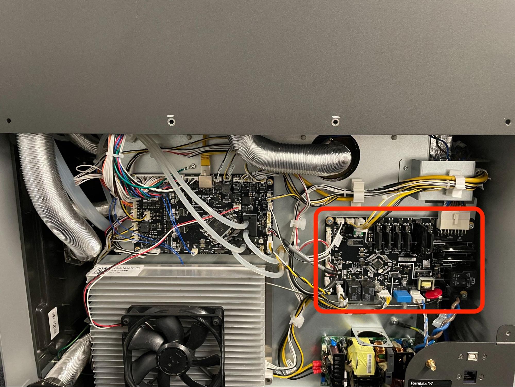
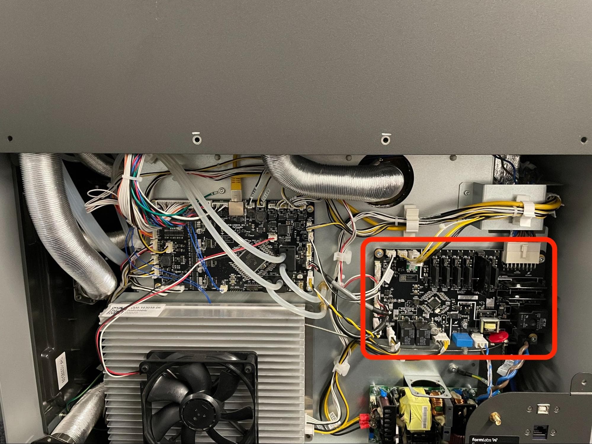
Locate the heater control board, positioned directly above the power supply.
Step 2: Disconnect the cables from the heater control board
Disconnect all cables from the heater control board. For cables that have a locking tab, make sure to disengage the locking tab first, then pull the connector away from the board via its plastic housing.
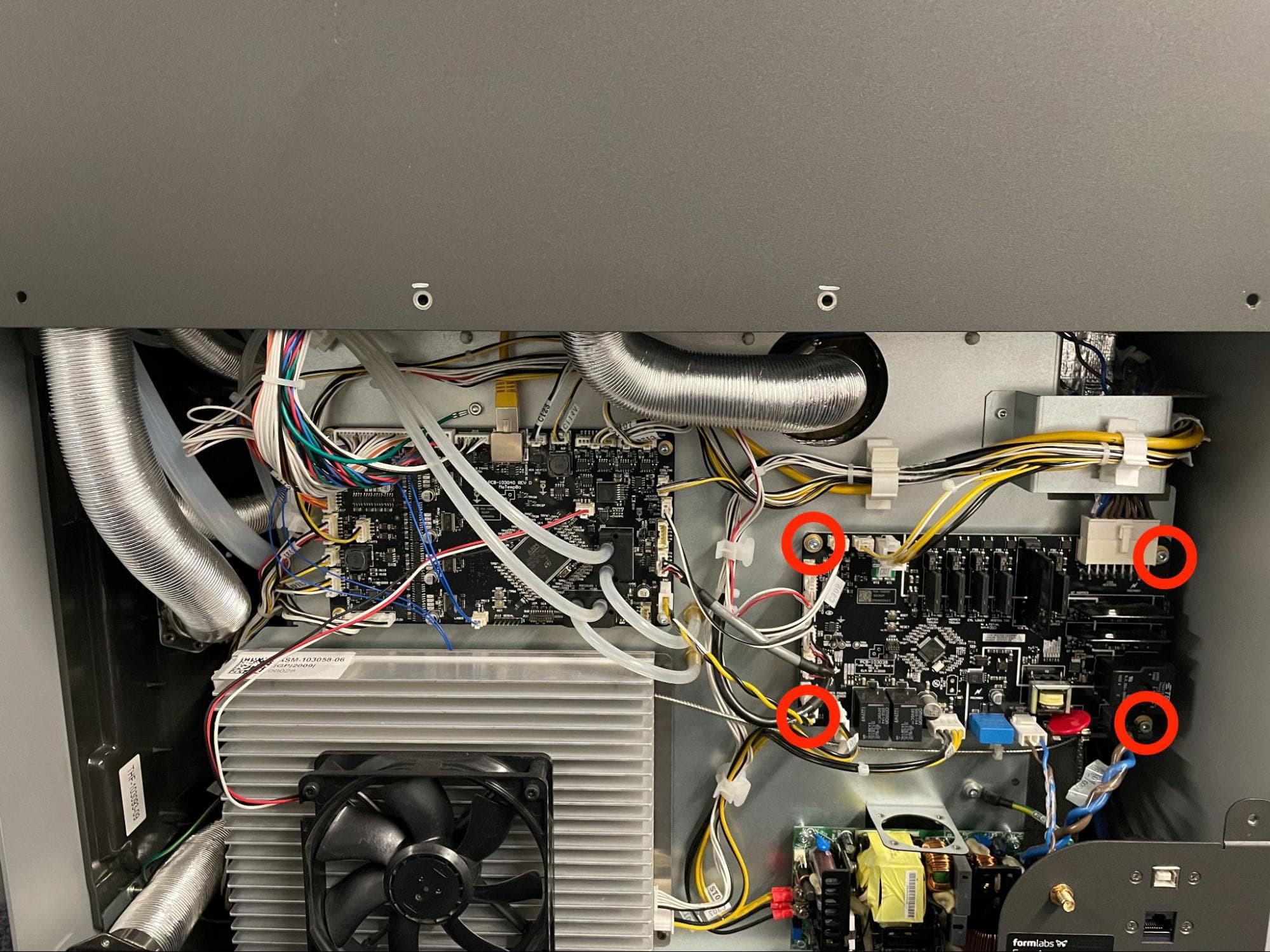
Using a 3 mm hex driver, loosen and remove the four 10 mm M4 socket head screws that secure the board to the printer. Set the screws aside. Maneuver the original heater control board away from the rear panel, being careful not to snag or pull any of the loose connectors. Set the board aside for disposal with electronic waste.
Installing the replacement heater control board
Overview: Mount, secure, and connect the replacement heater control board.
Step 1: Prepare the new heater control board
If you have not already, put on an antistatic wrist band and connect it to a known ground point. Do not connect the wristband any surfaces that are powder-coated or painted. Remove the replacement board from its packaging and locate the glass fuses included with the board.

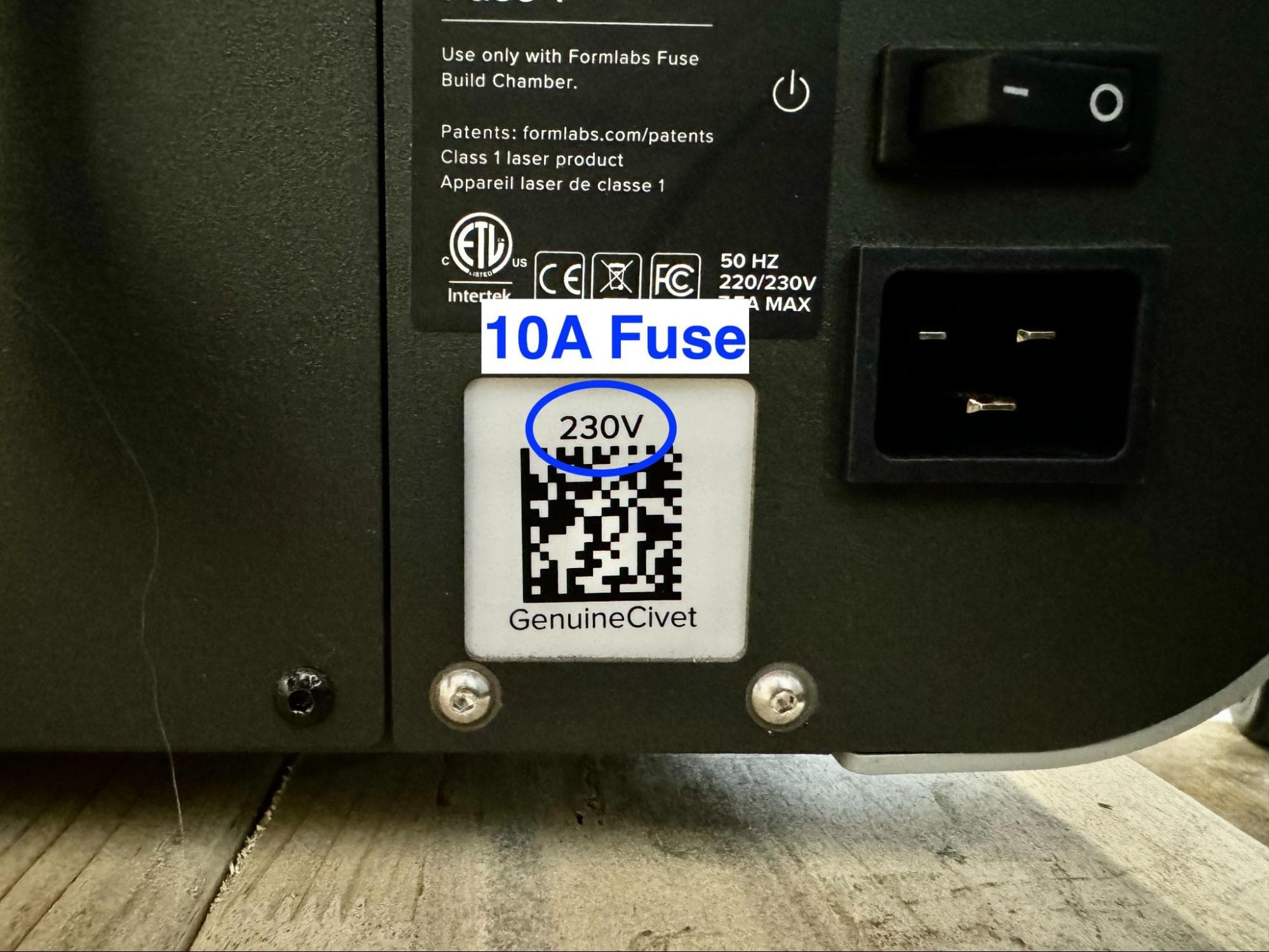
Refer to the serial name sticker on the back of the printer to confirm the printer’s voltage configuration, and thus which glass fuse to install into the replacement board:
Insert the correct glass fuse into the fuse holder on the replacement heater control board.

Step 2: Mount the heater control board
Orient the heater control board with the large AC harness connector at the top-right corner. Align the four screw holes in the board with the standoffs on the back of the printer. Ensure that none of the loose cables are trapped behind the board.
Step 3: Secure the heater control board
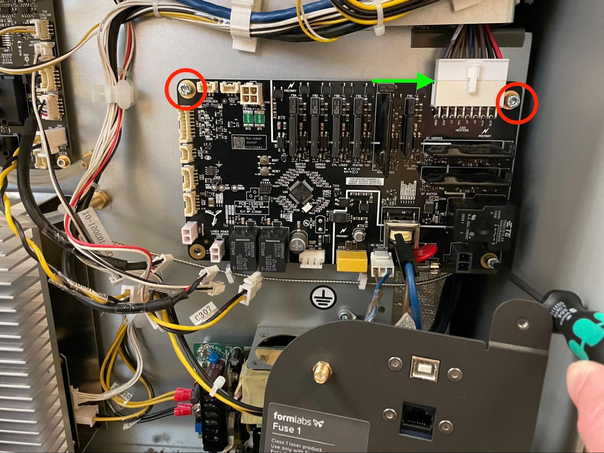
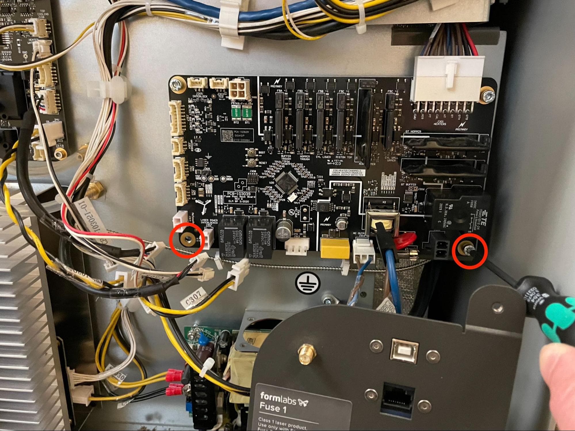
Connect the AC harness to help hold the heater control board in place. Thread one 10 mm M4 socket head screw into each of the screw holes. Using a 3 mm hex driver, tighten until snug.
Step 4: Reconnect the cables to the heater control board
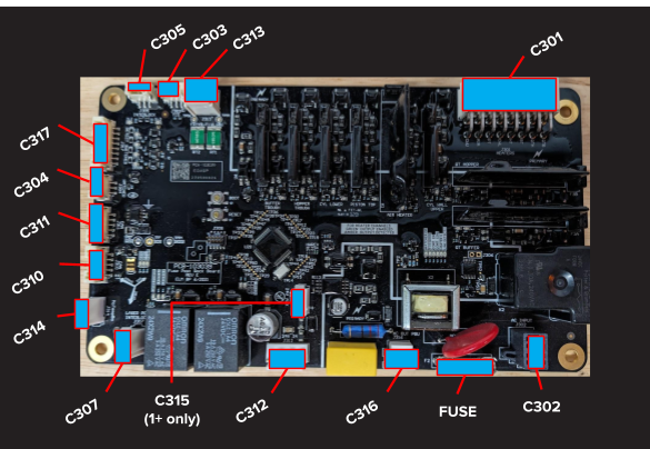
Connect all remaining cables to the new heater control board. Refer to the image here to map each connector with its socket.
Note:
Connector C315 is only used Fuse 1+ 30W printers. On Fuse 1 printers, this socket on the board is not used and stays empty.
Reinstalling the lower rear panel
Overview: After installing the replacement heater control board, reinstall and secure the lower rear panel.
Lift the I/O bulkhead panel and align the three screw holes with the corresponding screw holes in the printer frame. Thread one black 6 mm M4 button head screw into the screw hole on the right of the panel. Thread two chrome 6 mm M4 button head screws into the screw holes on the bottom of the panel. Using a 2.5 mm hex driver, tighten the screws until snug.
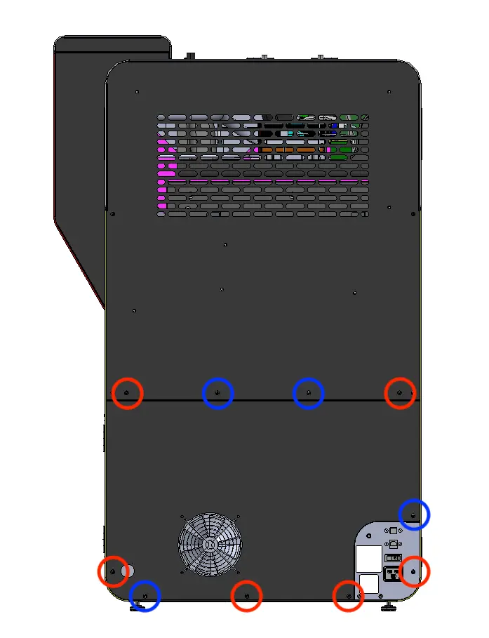
The six black lower rear panel screws are circled in red. The four chrome lower rear panel grounding screws are circled in blue.
Thread the panel screws into the indicated screw holes on the lower rear panel. Refer to the image for the correct locations of the black and chrome screws. Using a 2.5 mm hex driver, screw in the six black panel screws and four chrome panel grounding screws securing the lower rear panel to the printer.
Notice:
The placement of the chrome screws is critical to the printer's electrical grounding. Incorrect placement may lead to printer damage.
Step 3: Reinstall the Wi-Fi antenna (optional)
Screw the Wi-Fi antenna onto the jack on the back of the unit.
Step 4: Reconnect the nitrogen supply (Fuse 1+ 30W only)
Reconnect the nitrogen hose to the quick-disconnect fitting, if it was previously connected.
Finalizing the repair
Overview: After installing the replacement heater control board, power on the printer and perform final checks.
Step 1: Power on the printer
Connect the power cable to the printer and the power supply. The printer initializes.
Step 2: Update the printer's firmware
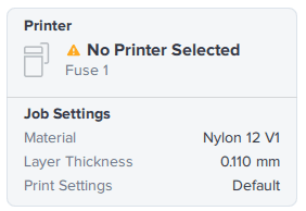
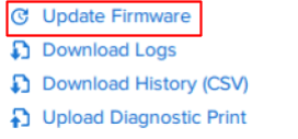
Open PreForm and connect to the printer via USB (preferred) or a local network. Download the latest firmware version from Formlabs. Manually update the printer’s firmware in PreForm by clicking the Printer box on the top right, selecting the printer from the list, clicking Update Firmware, then following the instructions in the dialog box that appears.
When the printer is ready, proceed with the update prompts on the touchscreen.
Step 3: Test the repair
Start a print. Monitor the printer to ensure that the print proceeds normally. Contact Formlabs Support or your certified service provider to share the results of the procedure.