
Tools:
Formlabs:
- Replacement Fuse Blast chamber LED module
- T20 Torx driver (provided with the Fuse Blast)
Third-party:
- T10 Torx driver
- 7 mm box wrench or needle nose pliers

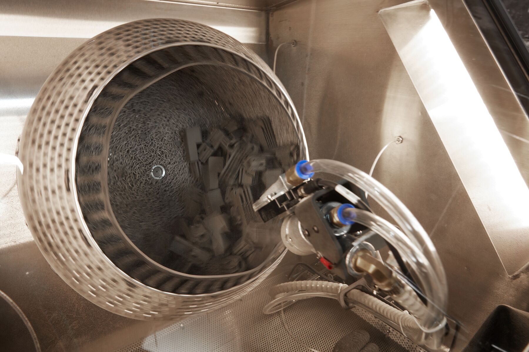
The Fuse Blast uses two banks of LEDs to light the blasting chamber during use. If one or both of these LED modules are faulty or malfunctioning, it will be more difficult to see your printed parts while you post-process them.
Use this guide to replace the chamber lights on a Fuse Blast.
Tools:
Formlabs:
Third-party:
Estimated time: 20–30 minutes per module
Warning:
The Fuse Blast is designed to contain fine particulate matter from media blasting and SLS 3D printing. Always wear an N95 respiratory mask when performing maintenance on a Fuse Blast unit.
Preparing the workspace
Overview: Prepare the Fuse Blast and a clean workspace for replacing the chamber lights.
Step 1: Prepare the workspace
Clear a workspace. Ensure that the workspace is well-ventilated, level, and clean.
Step 2: Unplug the machine
Disconnect the power cable from the machine before continuing with maintenance. Do not perform maintenance on the machine while it is connected to power. Wait five minutes after disconnecting the printer from power before proceeding.
Danger:
Performing this procedure on the Fuse Blast while it is plugged in increases the risk of electric shock. Never remove any external paneling while the Fuse Blast is plugged in. Never reconnect the Fuse Blast to power while the external paneling is uninstalled.
Step 3: Determine the LED module to be replaced
The Fuse Blast chamber is lit by two LED modules: one on the left wall and one on the right. If you are replacing the right-hand lights, continue. If you are replacing the left-hand lights, skip to Removing the left panel.
Removing the right-hand panels
Overview: Remove the right-rear and right-front panels to access the right-hand chamber lights.
Step 1: Unscrew the right-rear panel mounting screws
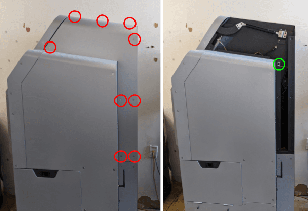
Using a T20 Torx driver, loosen and remove the nine silver T20 Torx screws securing the right-rear panel to the Fuse Blast. Set the screws aside.
Step 2: Remove the right-rear panel
Slide the panel up to free its locating feature, then remove the panel and set it aside.
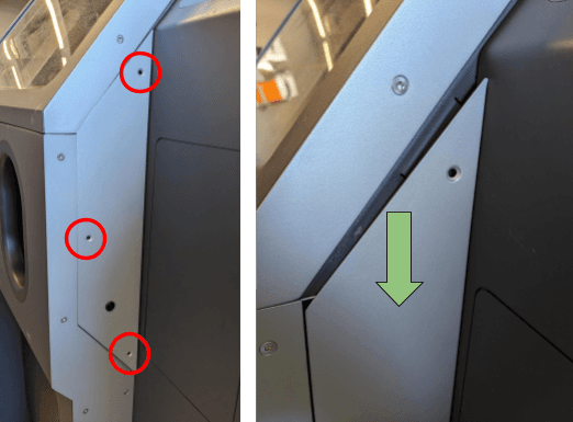
Using a T20 Torx driver, loosen and remove the three silver T20 Torx screws securing the right-front panel to the Fuse Blast. Set the screws aside.
Slide the panel down to release it, then tilt it to reveal its inner face.
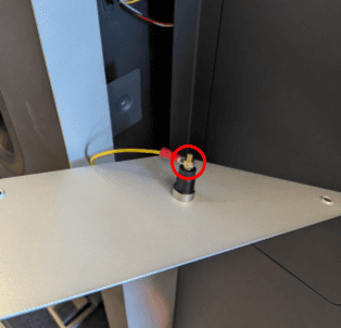
Using a 7 mm box wrench or needle nose pliers, unscrew the nut securing the grounding wire to the wrist strap socket on the right-front panel. Set the nut aside. Remove the grounding wire and set the panel aside.
Removing the right LED board
Overview: Unplug and remove the original right-hand LED board.
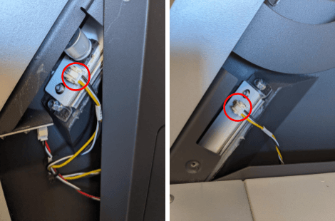
Locate the right-hand LED board. It is positioned partially behind the sidecar, with its ends visible behind the panels you removed in the previous steps. Unplug the cables from both ends of the LED board.
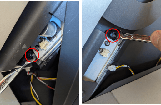
Using a 7 mm box wrench or needle nose pliers, carefully remove the two hex nuts securing the LED board to the Fuse Blast. Set the nuts aside.
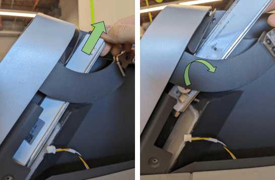
With the nuts removed, slide the LED board assembly upwards. Rotate the assembly to remove it through the top of the machine. You may have to flex the door bracket to provide enough clearance for the assembly to slide through.
Installing the replacement right LED board
Overview: Mount, secure, and connect the new right-hand LED board.
Step 1: Mount the LED board
Orient the LED board with the cable connectors facing you and the large round component at the bottom. Slide the assembly in through the top of the machine and position it into place, with the slots at the ends of the LED board frame over the threaded posts in the Fuse Blast.
Step 2: Secure the LED board
Thread one 7 mm hex nut onto both posts, then tighten until snug with a 7 mm box wrench or needle nose pliers.
Step 3: Reconnect the LED board cables
Reattach the connectors to either side of the new LED board.
Reinstalling the right-hand panels
Overview: Mount and secure the right-rear and right-front panels.
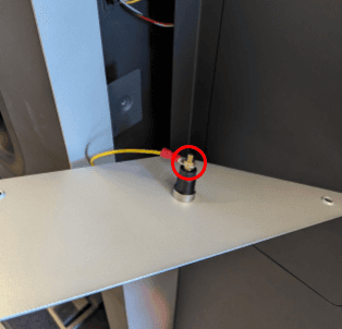
Attach the grounding wire to the post on the back of the right-front panel. Thread a 7 mm nut onto the post, then use a 7 mm box wrench or needle nose pliers to tighten until finger-tight.
Hold the right-front panel against the side of the Fuse Blast, and push it upwards into place. Make sure that the three screw holes in the panel align with the corresponding screw holes in the machine. Thread one T20 Torx screw into each of the screw holes, then use a T20 Torx driver to tighten until snug.
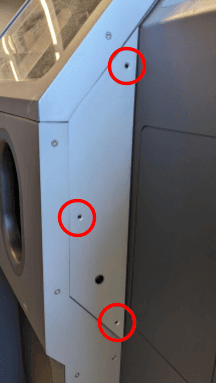
Step 3: Reinstall the right-rear panel
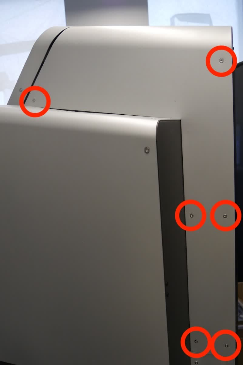
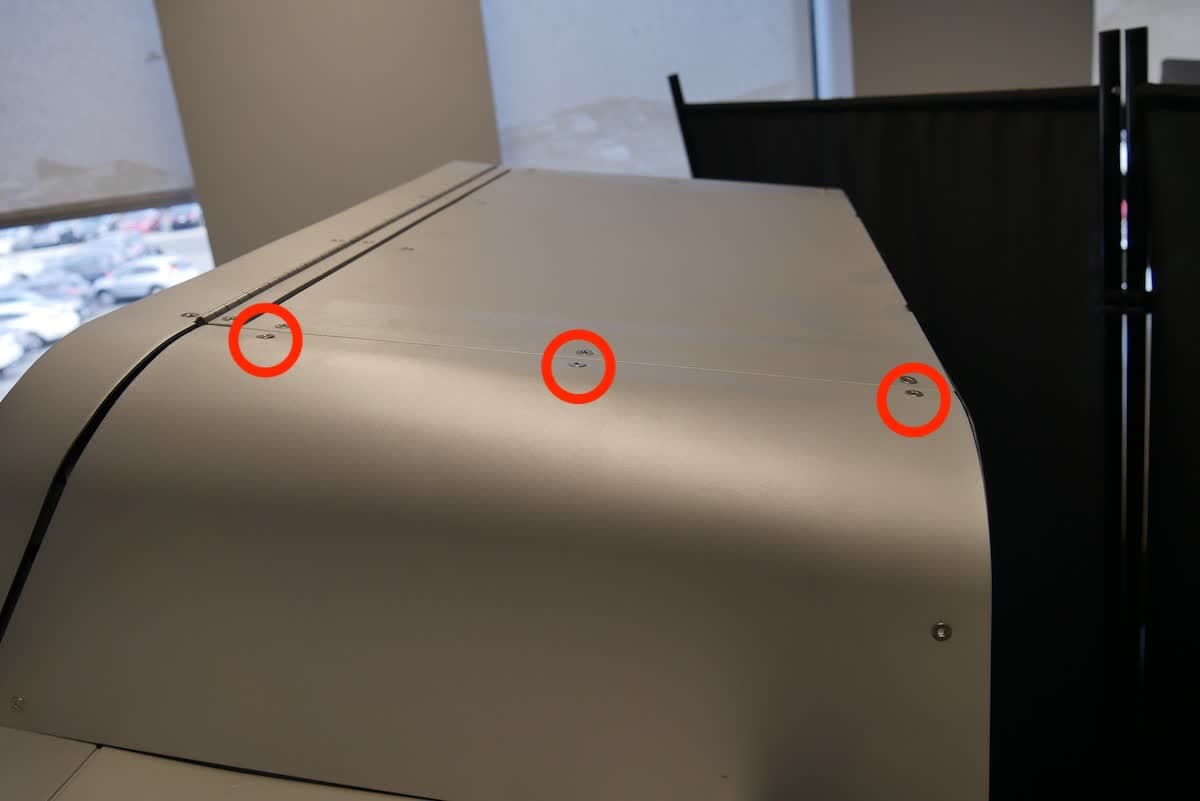
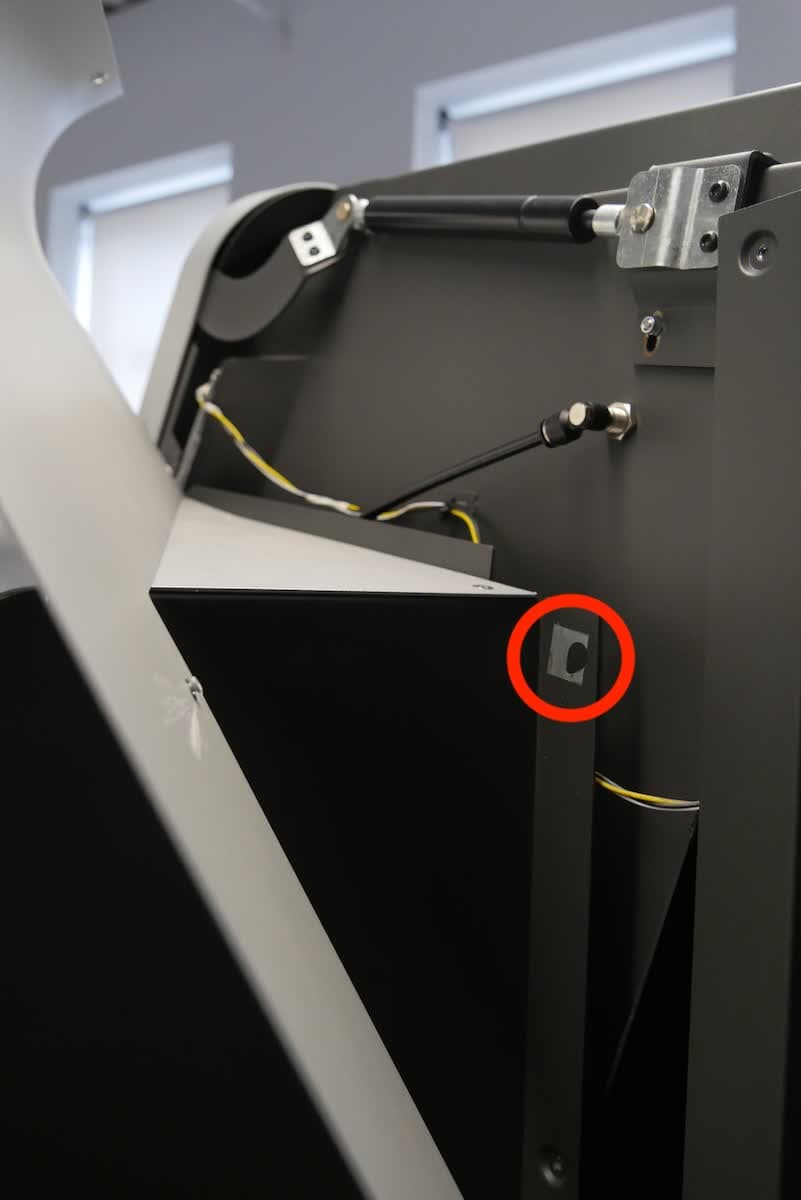
Mount the right-rear panel onto the machine, ensuring the locating feature on the shell aligns with the keyhole slot. Align the nine screw holes in the panel with the corresponding screw holes in the frame. Thread one T20 torx screw into each of the screw holes, then use a T20 Torx driver to tighten until snug.
If you are also replacing the left-hand LED board, continue. Otherwise, skip to Finalizing the repair.
Removing the left panel
Overview: Remove the left panel to access the left-hand chamber lights.
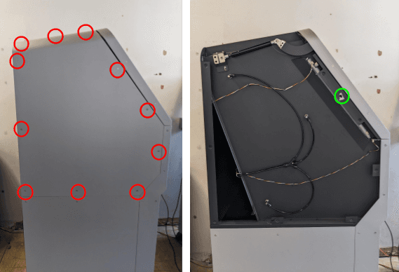
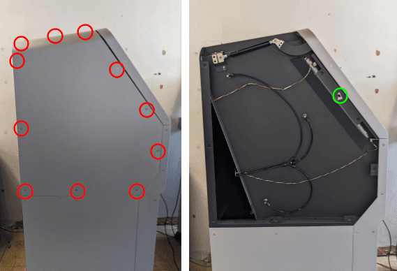
Using a T20 Torx driver, loosen and remove the 11 silver T20 screws securing the left panel to the Fuse Blast. Set the screws aside.
Slide the panel up to free its locating feature, then remove the panel and set it aside.
Removing the left LED board
Overview: Unplug and remove the original left-hand LED board.
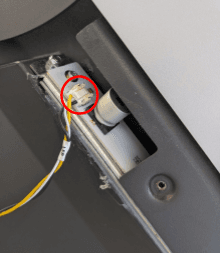
Locate the left-hand LED board. It is positioned partially behind the Fuse Blast frame, next to the chamber door. Unplug the cables from both ends of the LED board.
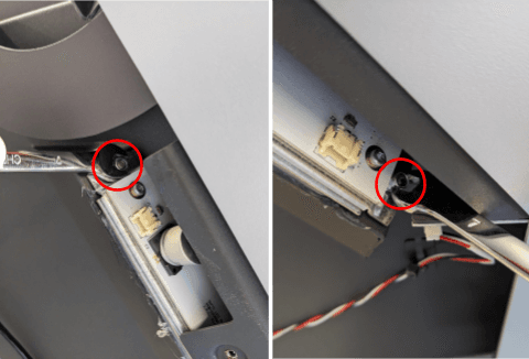
Using a 7 mm box wrench or needle nose pliers, carefully remove the two hex nuts securing the LED board to the Fuse Blast. Set the nuts aside.
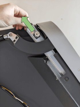
With the nuts removed, slide the LED board assembly upwards. Rotate the assembly to remove it through the top of the machine. You may have to flex the door bracket to provide enough clearance for the assembly to slide through.
Installing the replacement left LED board
Overview: Mount, secure, and connect the new left-hand LED board.
Step 1: Mount the LED board
Orient the LED board with the cable connectors facing you and the large round component at the top. Slide the assembly in through the top of the machine and position it into place, with the slots at the ends of the LED board frame over the threaded posts in the Fuse Blast.
Step 2: Secure the LED board
Thread one 7 mm hex nut onto both posts, then tighten until snug with a 7 mm box wrench or needle nose pliers.
Step 3: Reconnect the LED board cables
Reattach the connectors to either side of the new LED board.
Reinstalling the left panel
Overview: Mount and secure the left panel.
Mount the left panel onto the machine, ensuring the locating feature on the shell aligns with the keyhole slot. Align the 11 screw holes in the panel with the corresponding screw holes in the frame.
Thread one T20 Torx screw into each of the 11 screw holes, then use a T20 Torx driver to tighten until snug.
Finalizing the repair
Overview: After replacing the chamber lights, power on the machine and perform final checks.
Step 1: Power on the machine
Connect the power cable to the machine and the power supply. Flip the power switch on the back of the machine to the ON position. The machine initializes.
Step 2: Test the repair
Activate the chamber lights, either by tapping the light icon on the touchscreen or by starting a blasting cycle. Check that the LEDs turn on and the chamber is well-lit.