WHITE PAPER
Formlabs Logo

Replacing the Fuse Blast ionizer

Replacing the Fuse Blast ionizer

The Fuse Blast has an inline ionizer on the blast gun that rinses abrasive dust and residual powder from printed parts. If the ionizer or its cable is faulty or damaged, the Fuse Blast will be unable to clean parts effectively.

Use this guide to replace the Fuse Blast ionizer and cable.

Required supplies:

Required supplies:

Formlabs:

  • Replacement ionizer kit (RB-FB-IONZ-01)
    • Ionizer
    • Ionizer cable
    • T25 Torx screws (2x)
    • Cable clamp
  • T20 Torx driver (provided with the Fuse Blast)

Third-party:

  • T25 Torx driver
  • Slotted screwdriver or similar tool
  • Zip ties
  • Pliers (optional)
  • Nitrile gloves
Estimated time: 20–30 minutes

Danger:

Read and follow all safety instructions and warnings in the operator manual. Replacement with incorrect parts can lead to burns, shock, fire, or explosion. Dispose of all parts in accordance with local regulations.

Preparing the workspace

Overview: Prepare the Fuse Blast and a clean workspace for replacing the ionizer and cable.

Step 1: Prepare the workspace

Clear a workspace. Ensure that the workspace is well-ventilated, level, and clean.

Step 2: Unplug the machine

Disconnect the power cable from the machine before continuing with maintenance. Do not perform maintenance on the machine while it is connected to power. Wait five minutes after disconnecting the printer from power before proceeding.

Danger:

Performing this procedure on the Fuse Blast while it is plugged in increases the risk of electric shock. Never remove any external paneling while the Fuse Blast is plugged in. Never reconnect the Fuse Blast to power while the external paneling is uninstalled.

Removing the upper sidecar panel

Overview: Uninstall the upper sidecar panel to access one end of the ionizer cable.

Notice:

The Fuse Blast contains sensitive electronic components. Ground yourself before touching any electronics in the machine by using an antistatic wrist band or touching a grounded piece of metal.

Step 1: Remove the upper sidecar panel retention screws

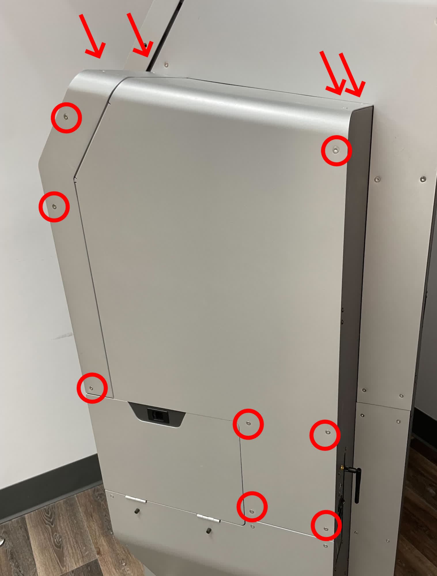
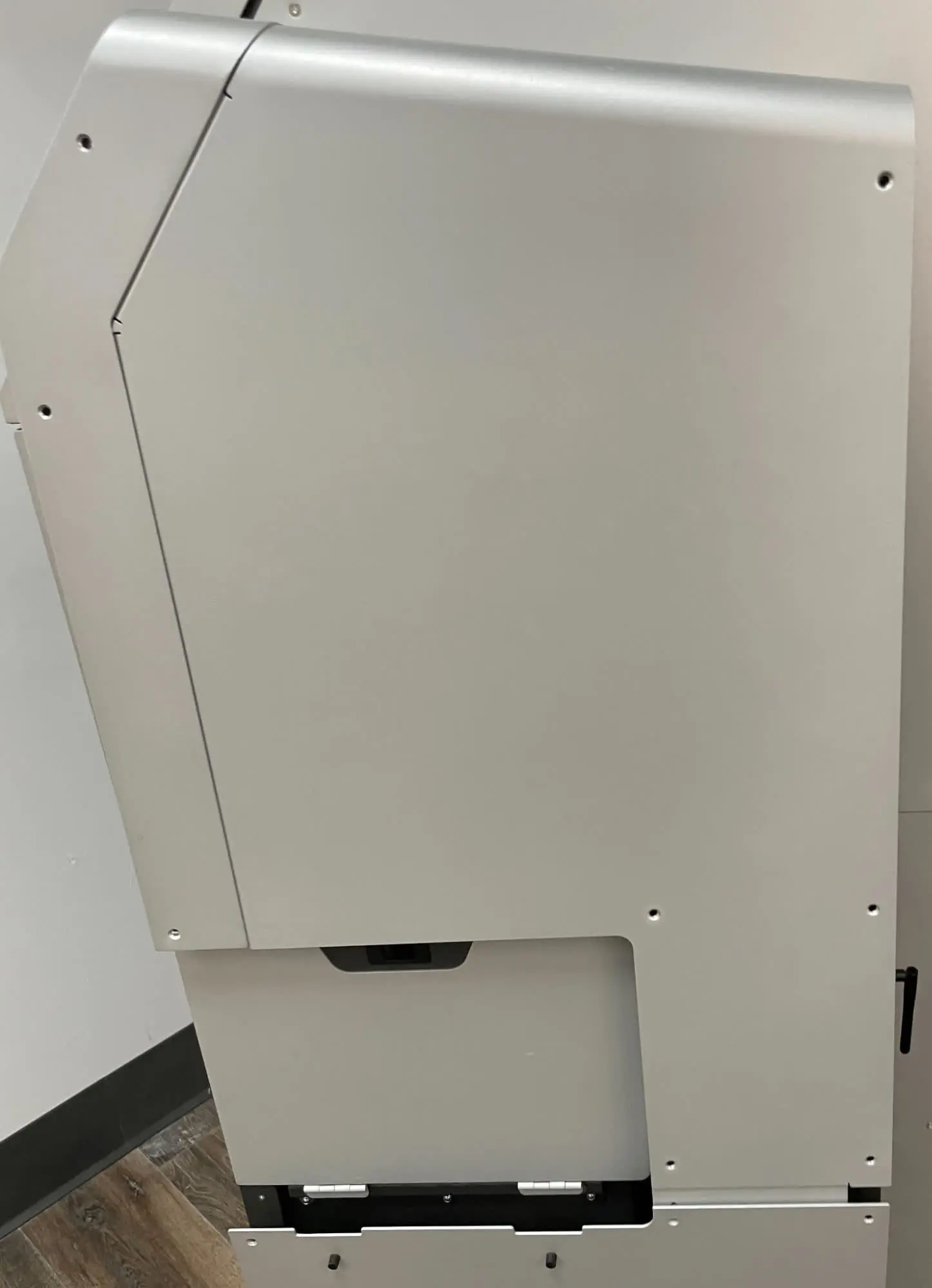
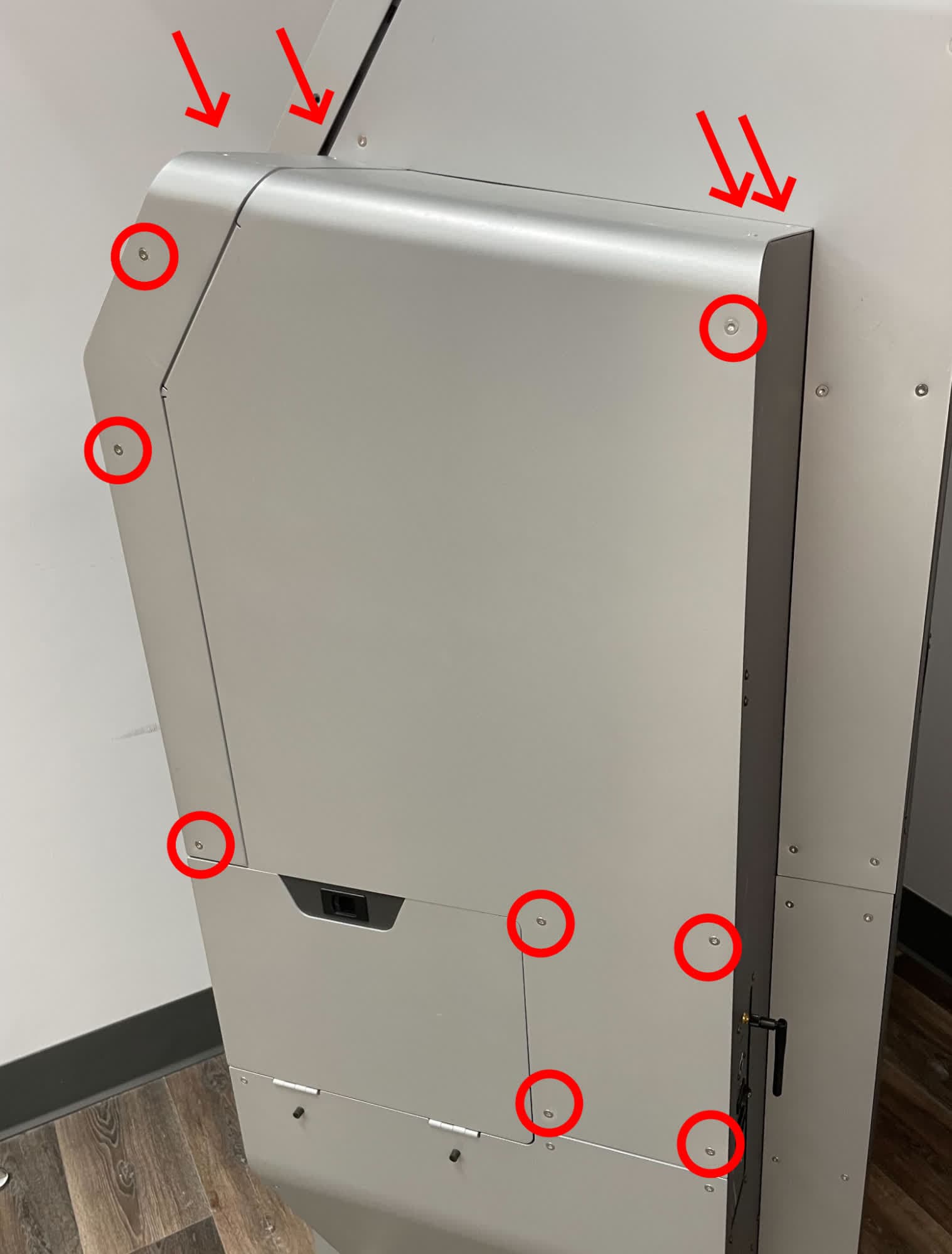
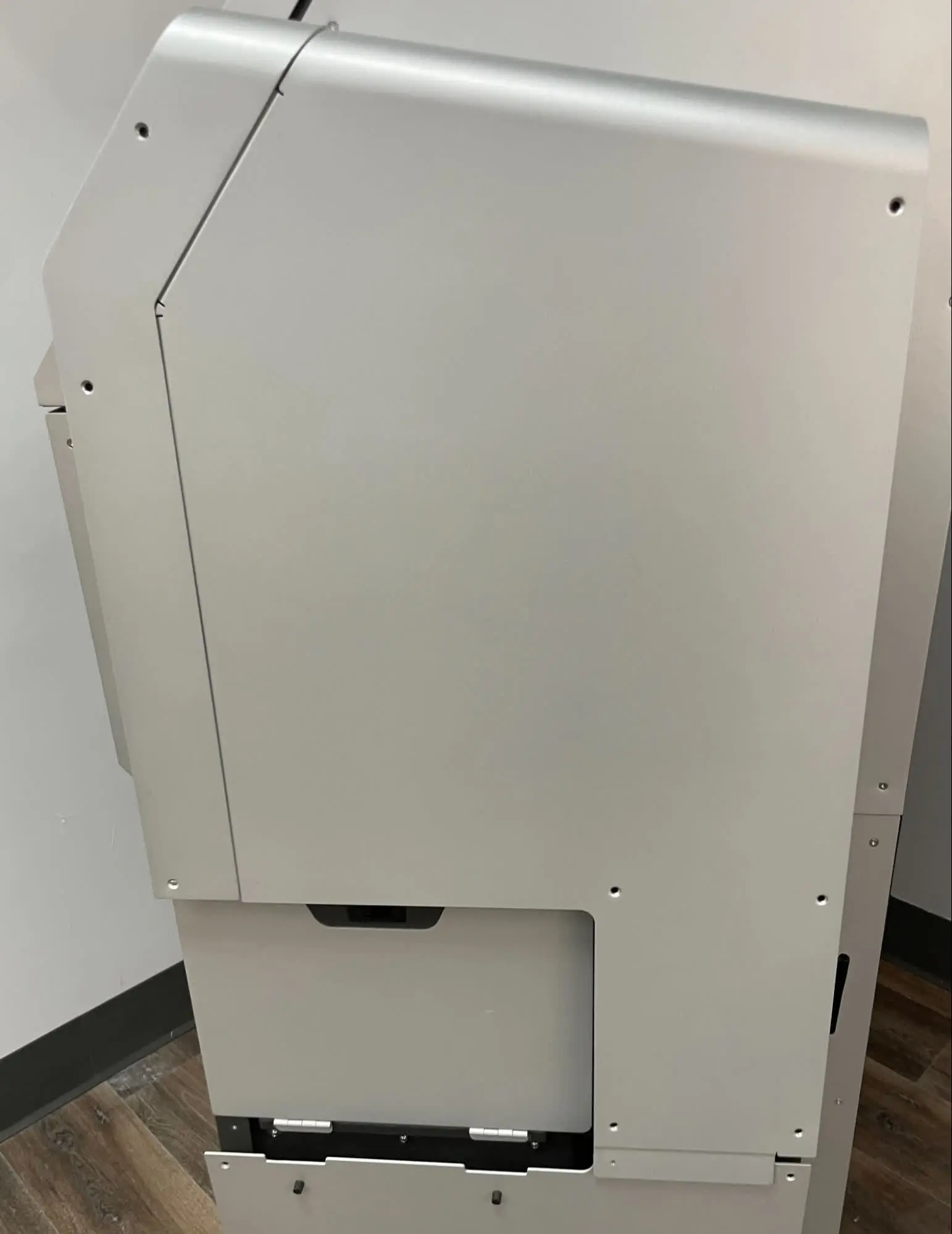
The air metering valve is located in the sidecar on the right side of the machine. Using a T20 Torx driver, loosen and remove the 12 T20 Torx screws securing the upper sidecar panel to the Fuse Blast. Set the screws aside.

Step 1: Remove the upper sidecar panel retention screws

Step 2: Remove the lower sidecar panel retention screws

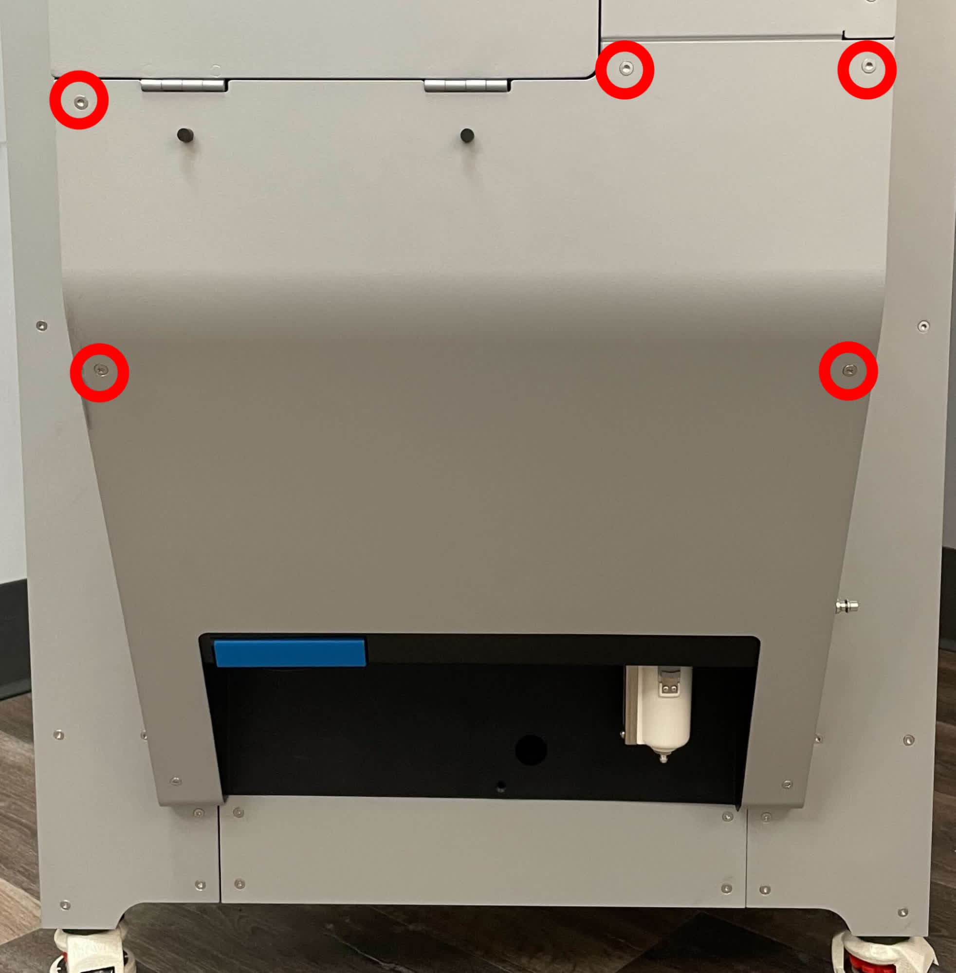
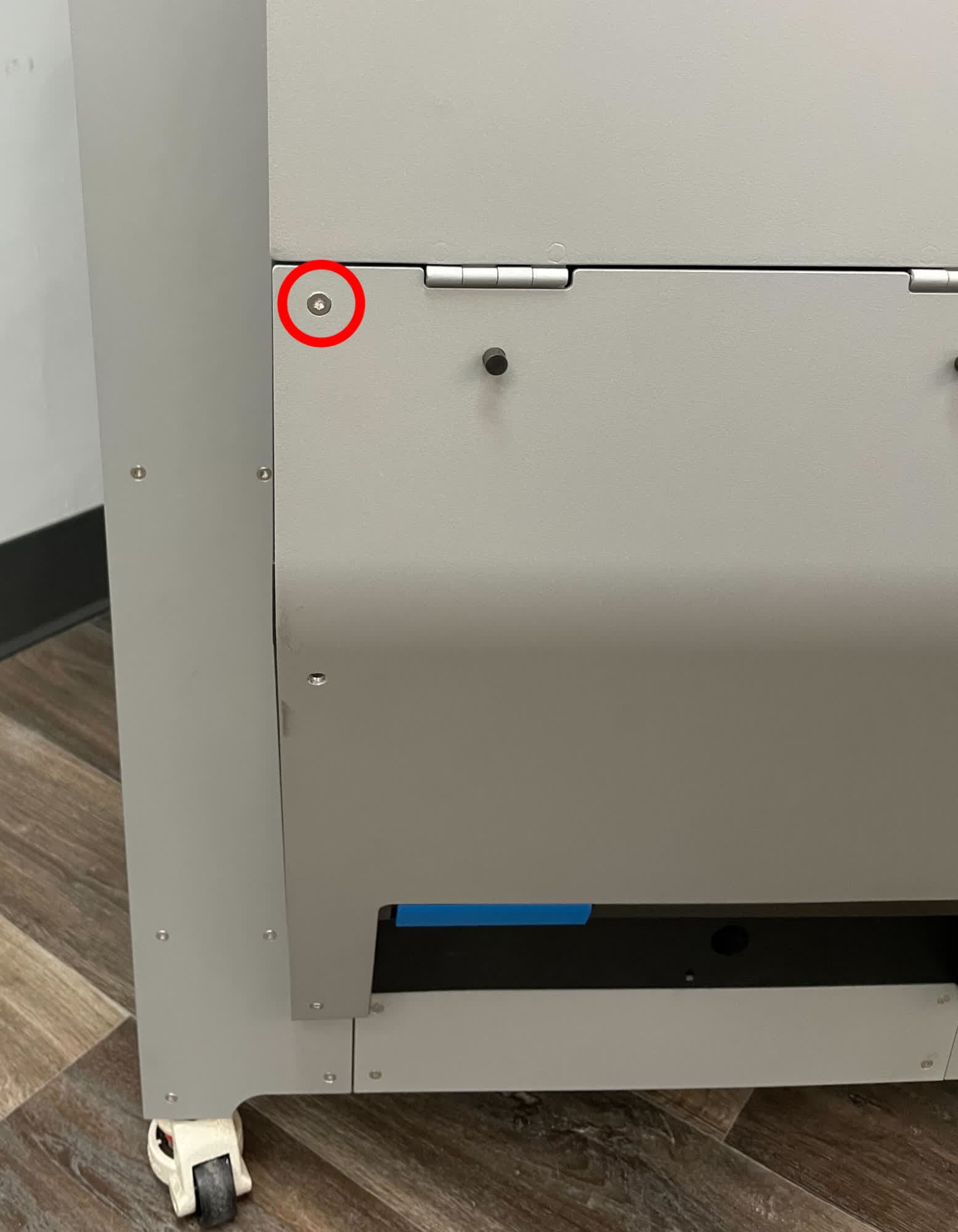
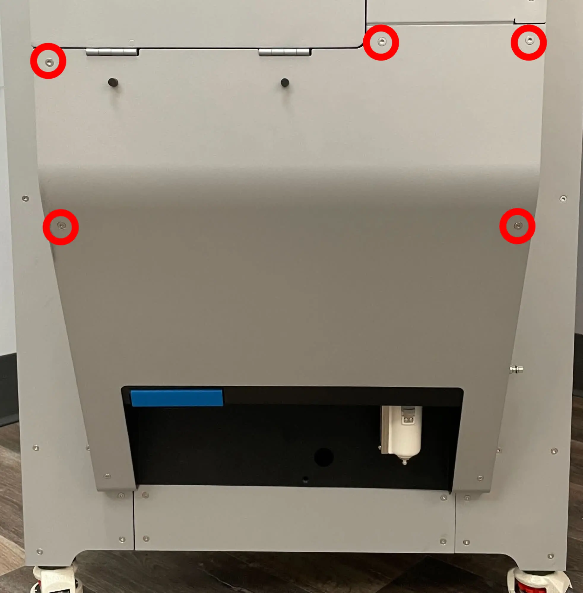
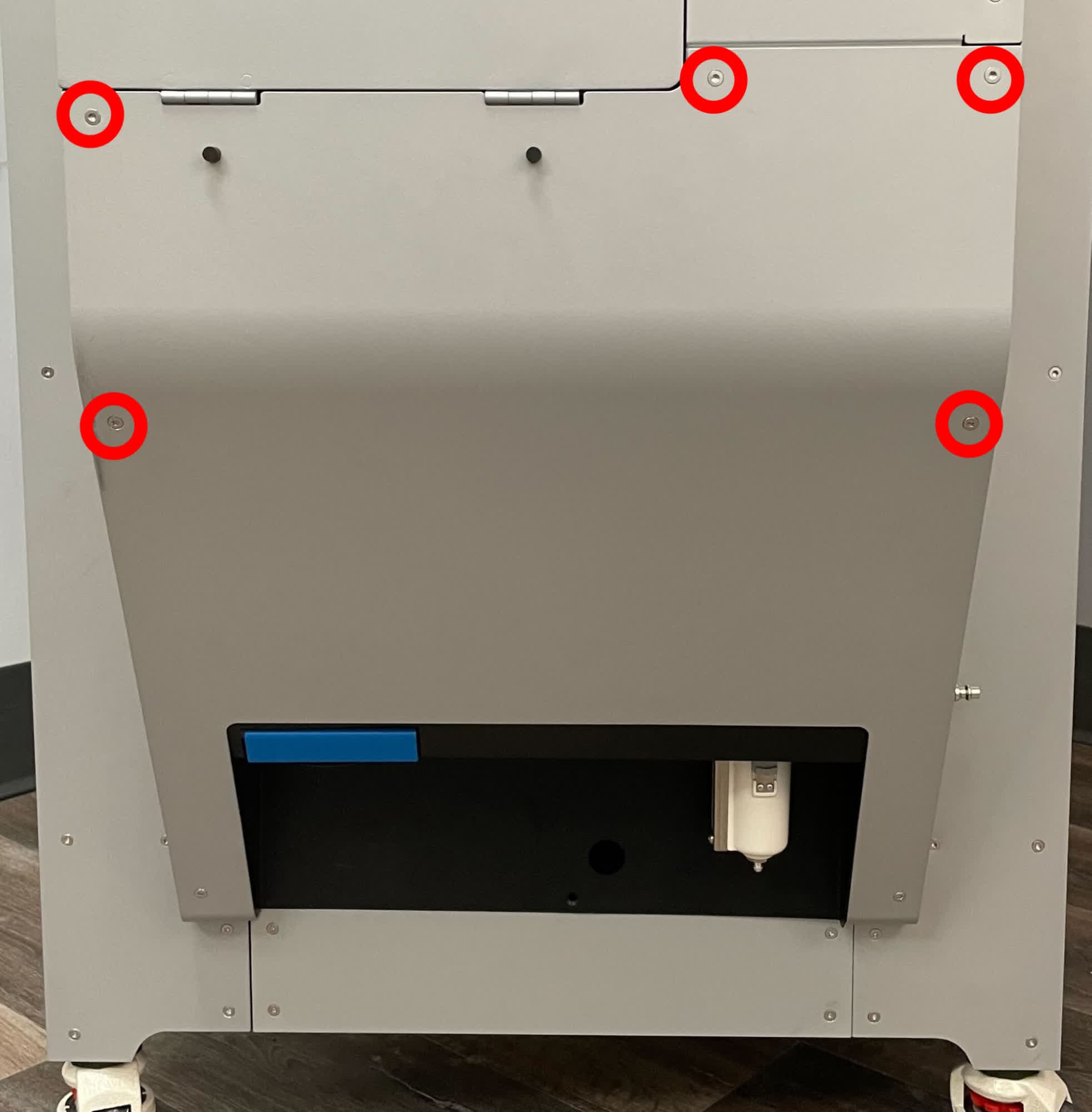
The lower sidecar panel must be moved slightly to free the upper sidecar panel. Using a T20 Torx driver, loosen and remove the five T20 Torx screws shown above. Set the screws aside. Do not remove the two screws at the bottom of the lower sidecar panel.

Step 2: Remove the lower sidecar panel retention screws

Step 3: Remove the upper sidecar panel

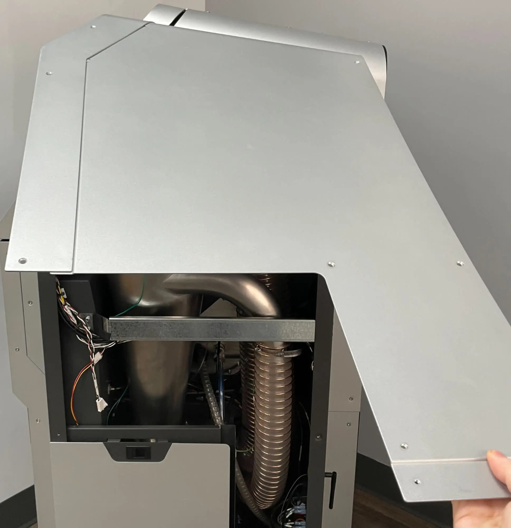
Step 3: Remove the upper sidecar panel

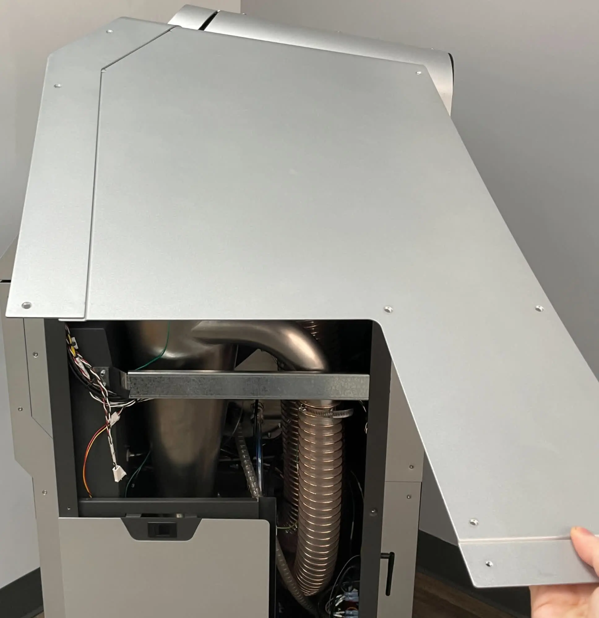
Untuck the bottom of the upper sidebar panel from behind the lower sidecar panel. Rotate the panel upwards until it is horizontal. Once it is horizontal, pull forward to disengage it. Set the upper sidecar panel aside.

Step 4: Partially secure the lower sidecar panel

Thread at least one of the lower sidecar panel retention screws back into the lower sidecar panel to avoid inadvertently bending it.

Step 4: Partially secure the lower sidecar panel

Removing the ionizer and cable

Overview: Uninstall the original ionizer and its cable.

Step 1: Disconnect the part rinse tubing

Step 1: Disconnect the part rinse tubing

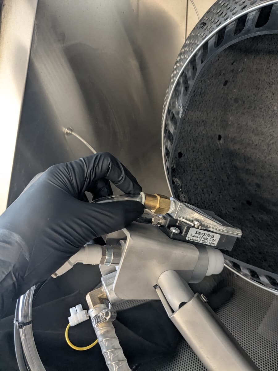
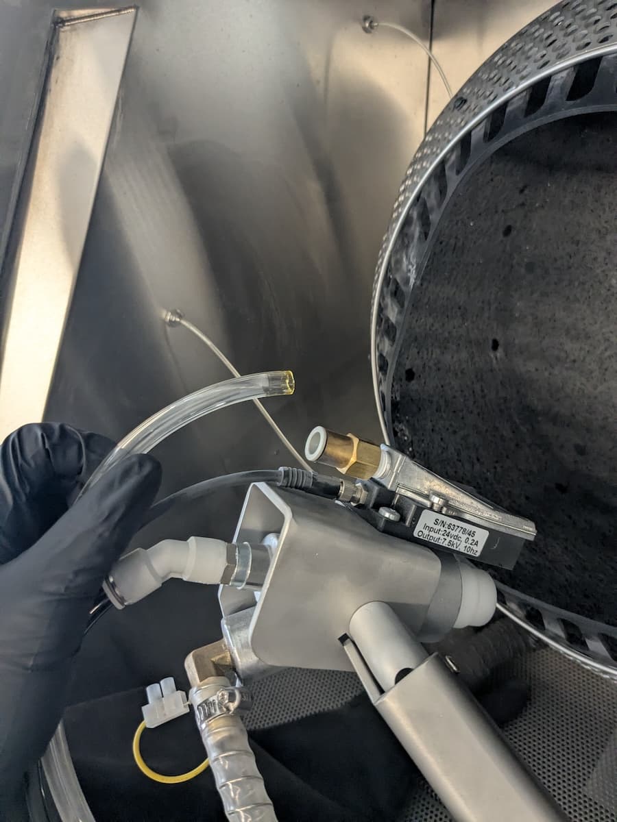
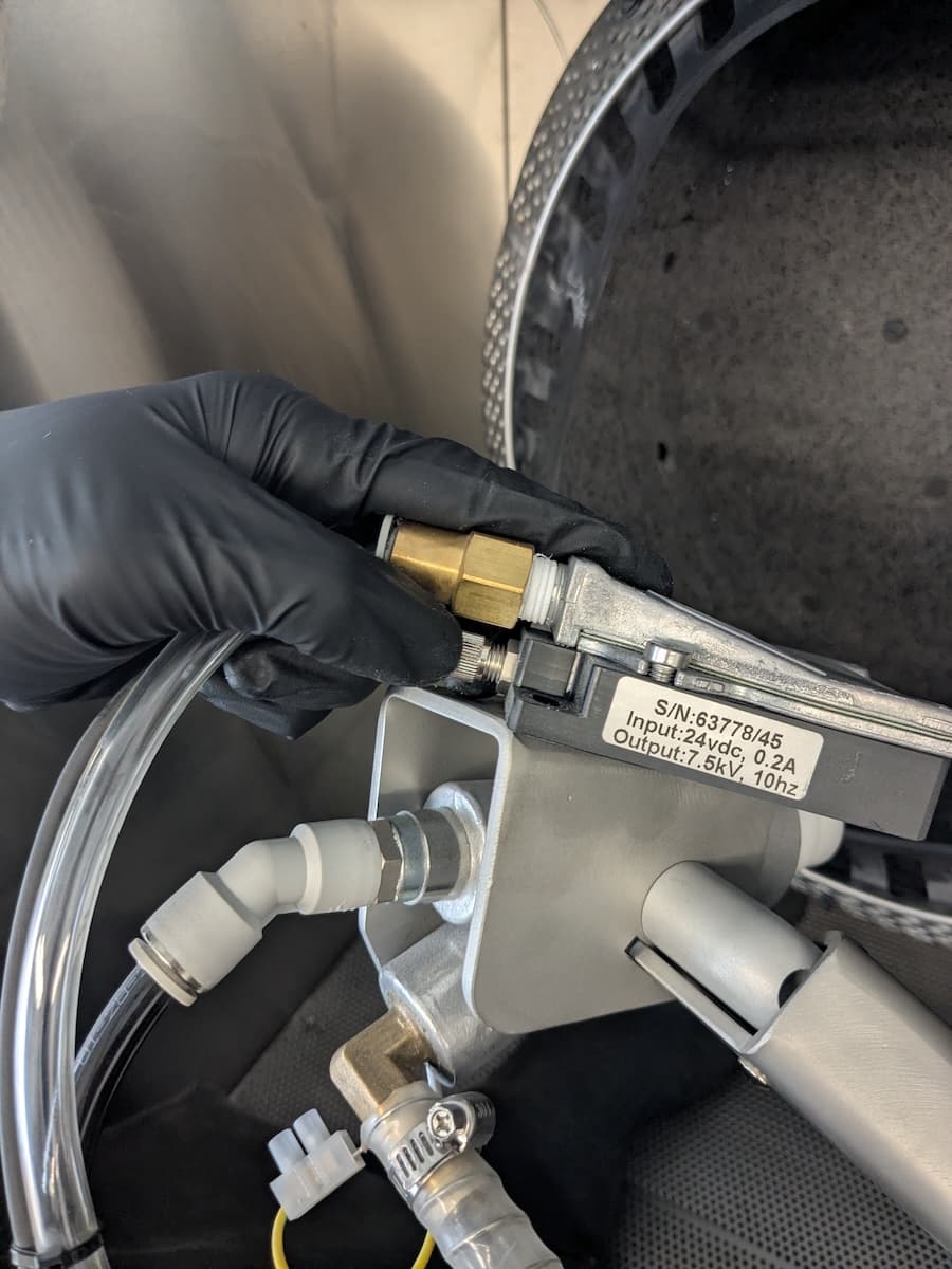
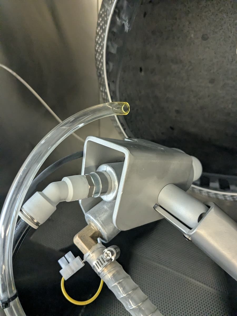
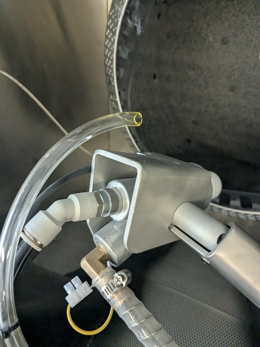
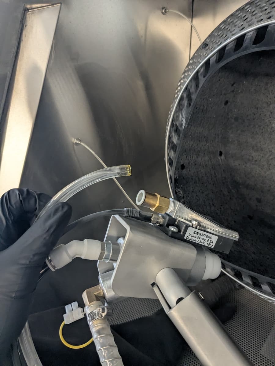
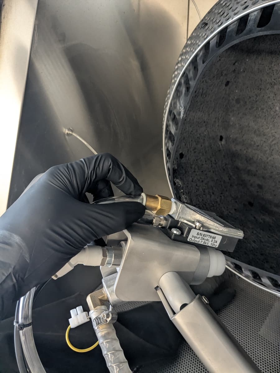
Open the blasting chamber door. Disconnect the part rinse tubing from the ionizer by pressing on the push-to-connect fitting and pulling out the tubing.

Step 2: Disconnect the ionizer cable from the ionizer

Step 2: Disconnect the ionizer cable from the ionizer

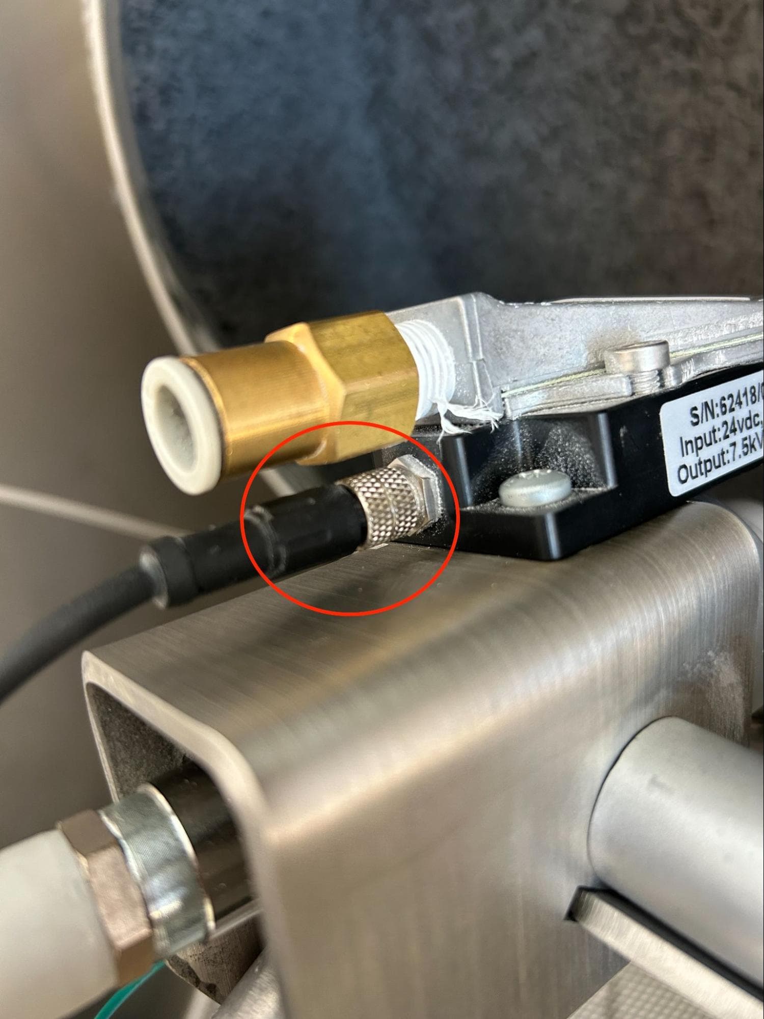
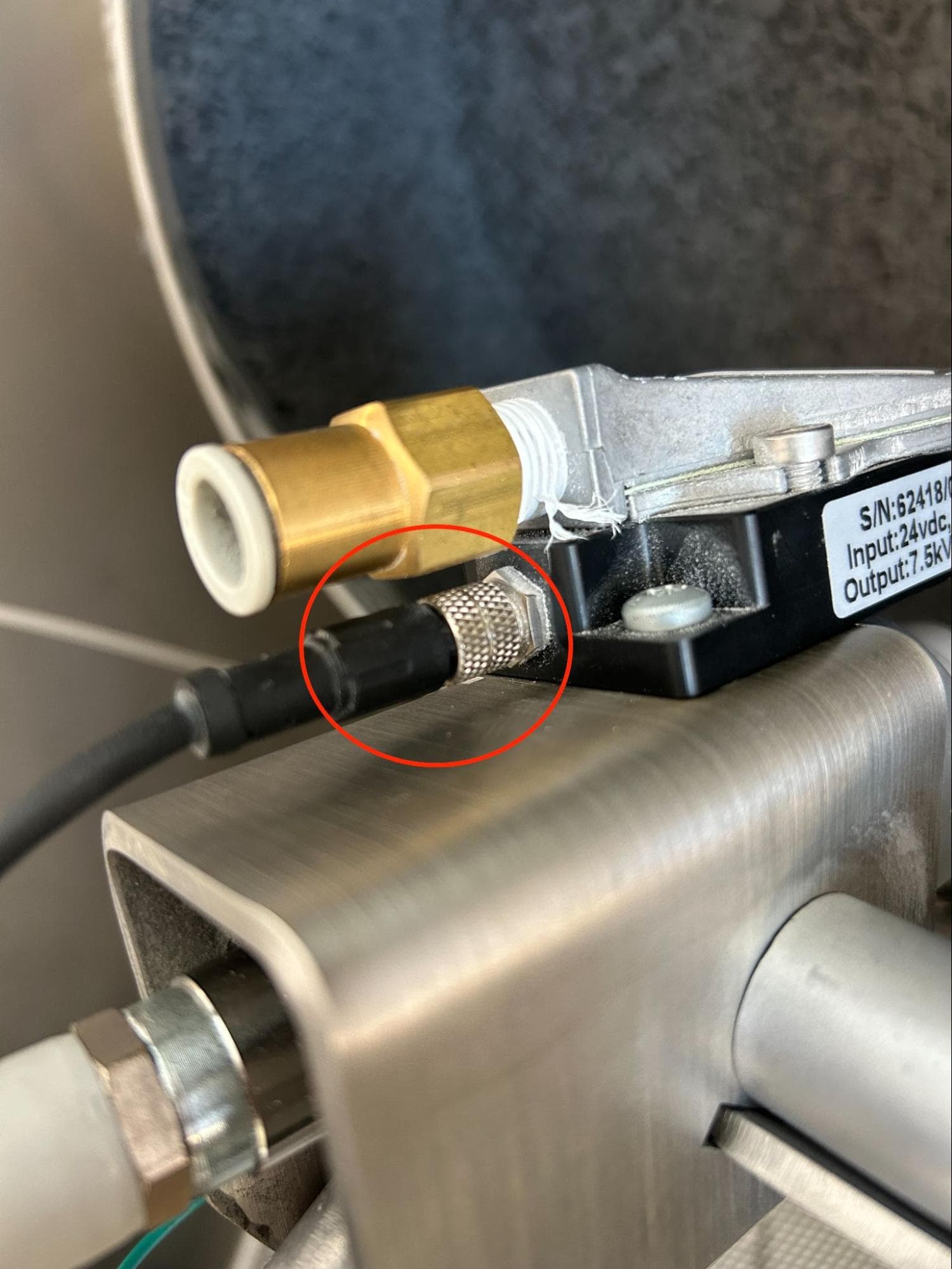
Disconnect the ionizer cable by unscrewing the threaded connector completely and pulling out the cable. It may be easier to access the threaded connector after separating the ionizer from the blast gun.

Step 3: Remove the ionizer

Step 3: Remove the ionizer

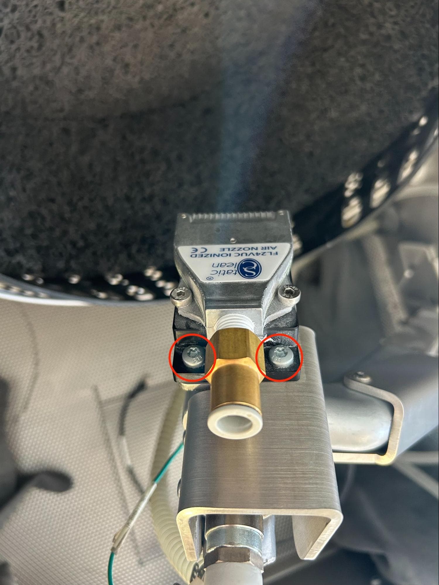
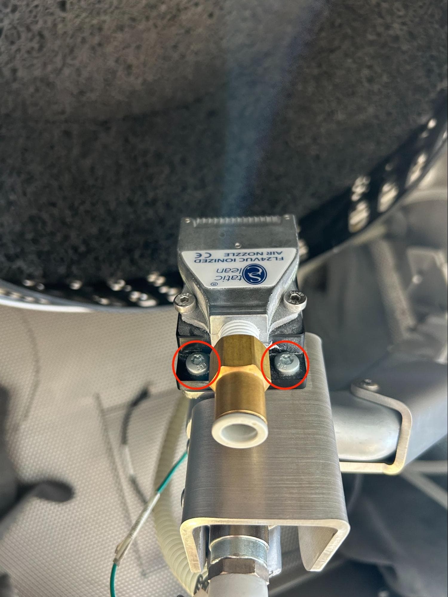
The ionizer is secured to the blast gun with two screws. Using a T25 Torx driver, loosen and remove the screws. Set the screws and ionizer aside for disposal with electronic waste.

Step 4: Disconnect the ionizer cable from its extension cable

Step 4: Disconnect the ionizer cable from its extension cable

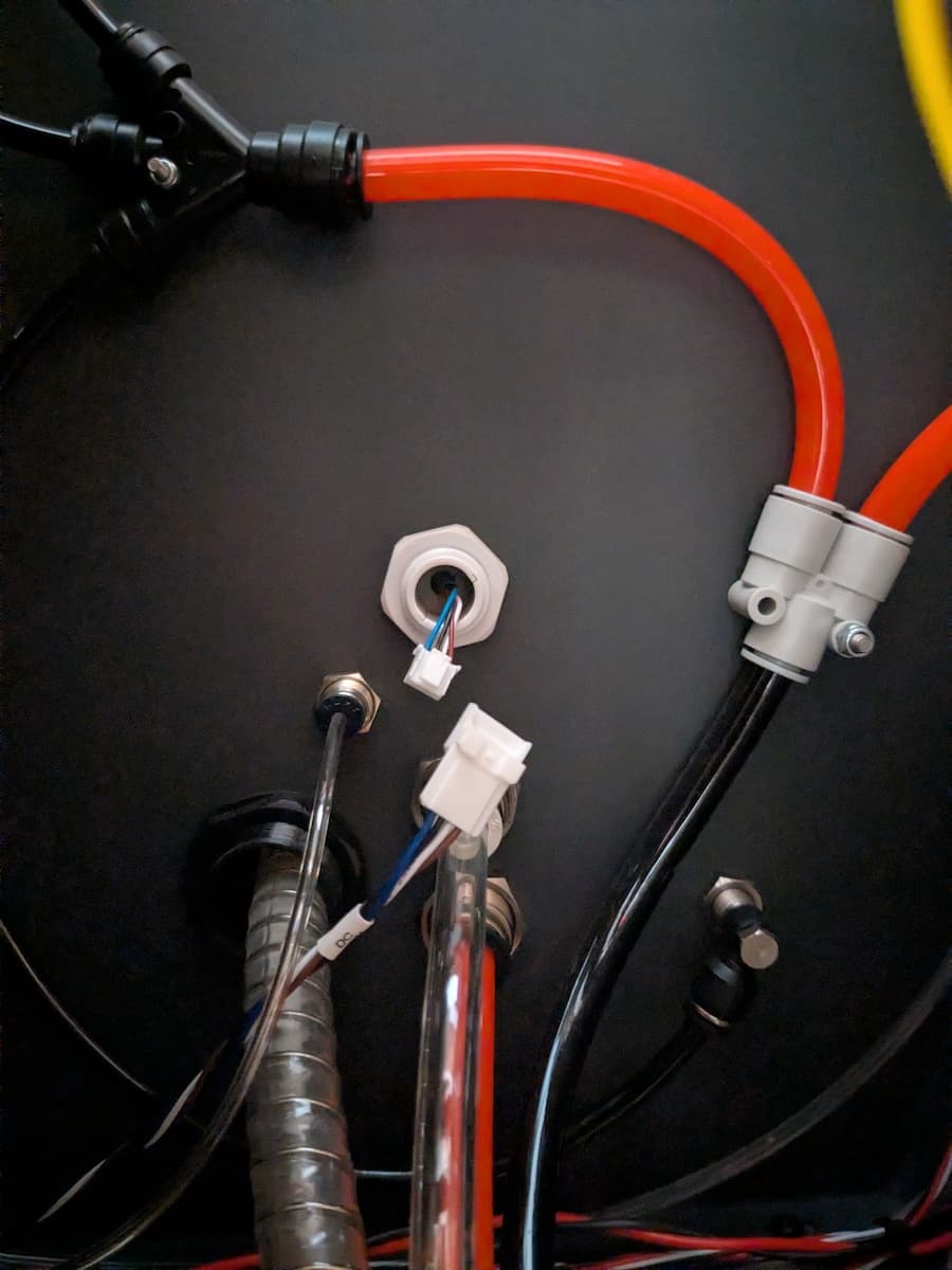
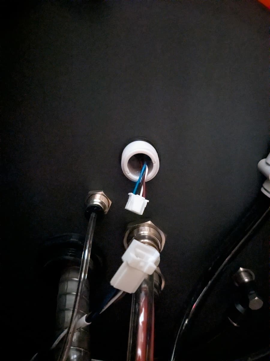
The ionizer cable passes through the right wall of the blasting chamber and connects to an extension cable, which in turn connects to the Fuse Blast motherboard. Follow the cable and locate the end behind the upper sidecar panel. Squeeze the clip and separate the cable connectors. Do not pull on the wires themselves.

Step 5: Remove the ionizer cable

Step 5: Remove the ionizer cable

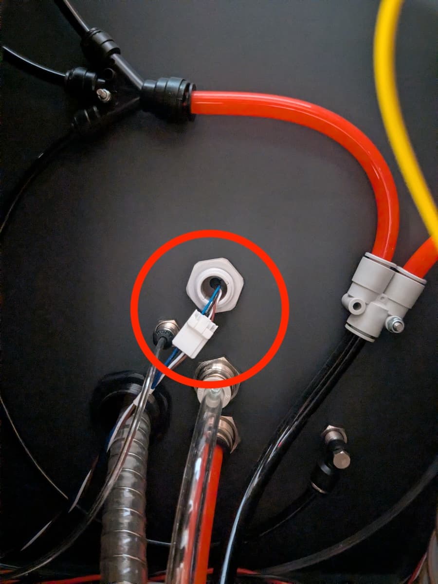
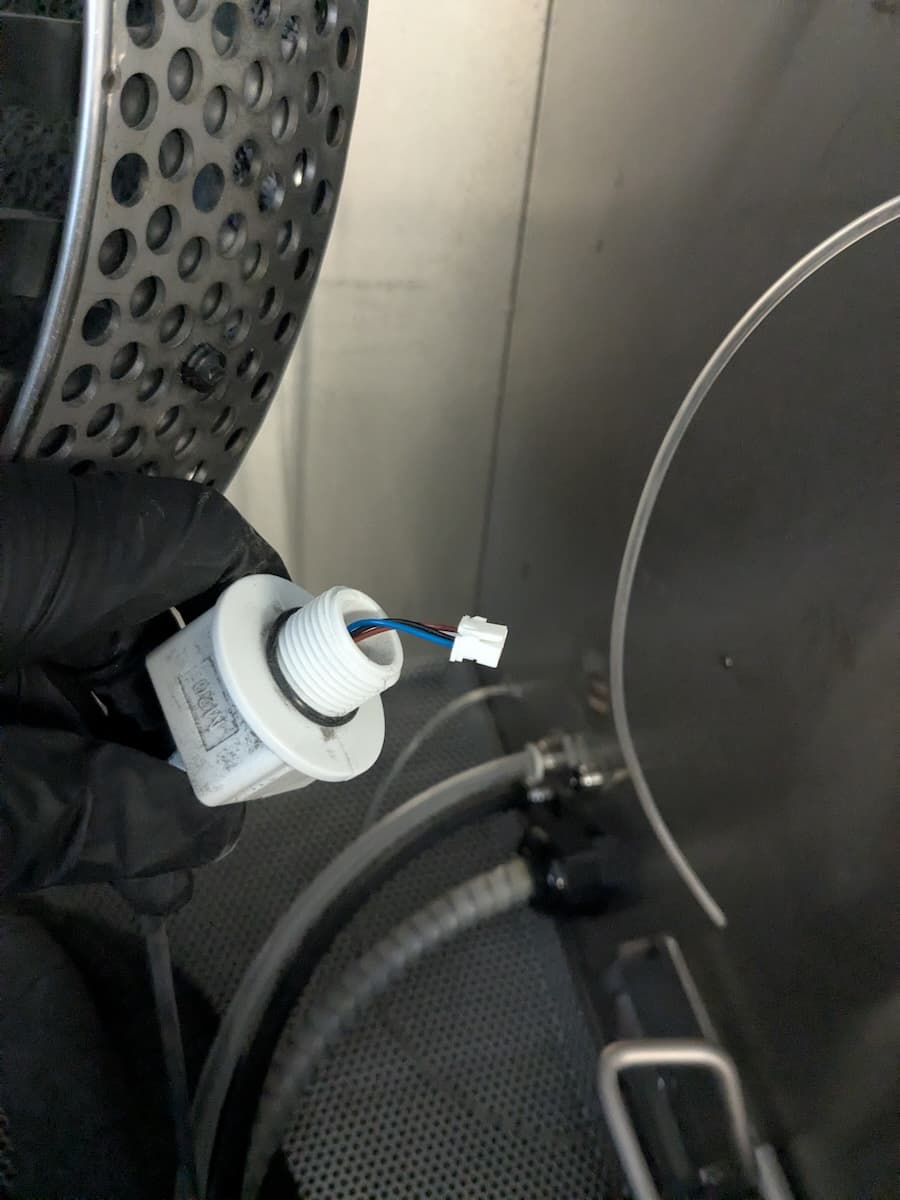
The ionizer cable is held in place by a cable clamp that passes through the right wall of the blasting chamber. Unscrew the cable clamp retention nut, then pull the cable clamp into the blasting chamber. Use a pair of pliers to loosen the nut, if necessary.

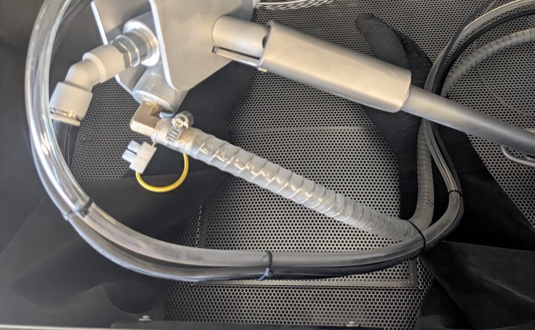
Carefully cut the zip ties securing the ionizer cable to the part rinse tubing. Set the cable and clamp aside for disposal.

Step 5: Remove the ionizer cable

Installing the replacement ionizer and cable

Overview: Route the new ionizer cable and mount, secure, and connect the ionizer.

Step 1: Prepare the cable clamp

Step 1: Prepare the cable clamp

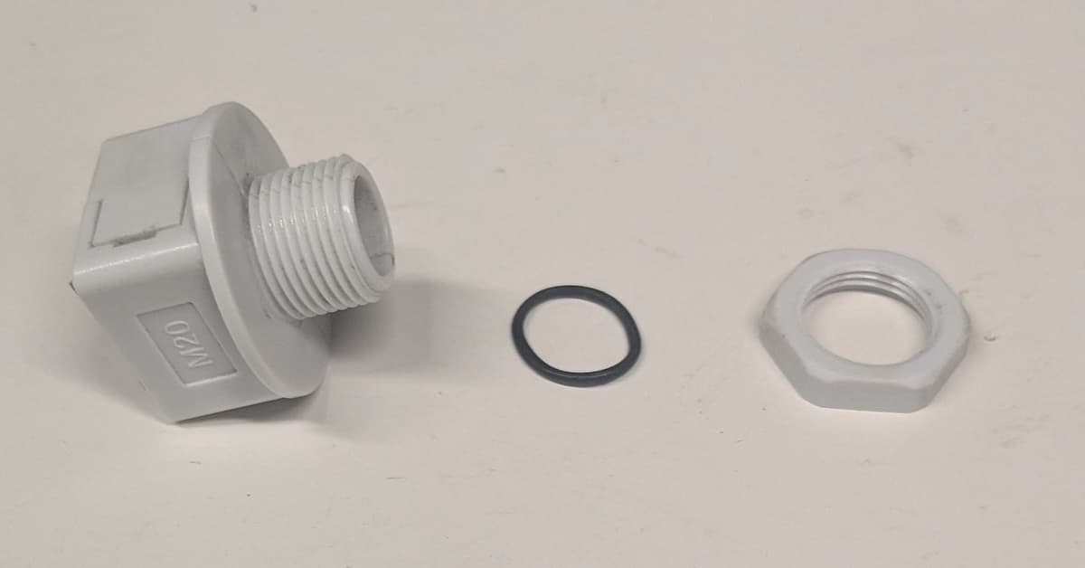
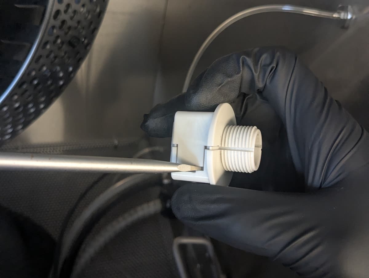
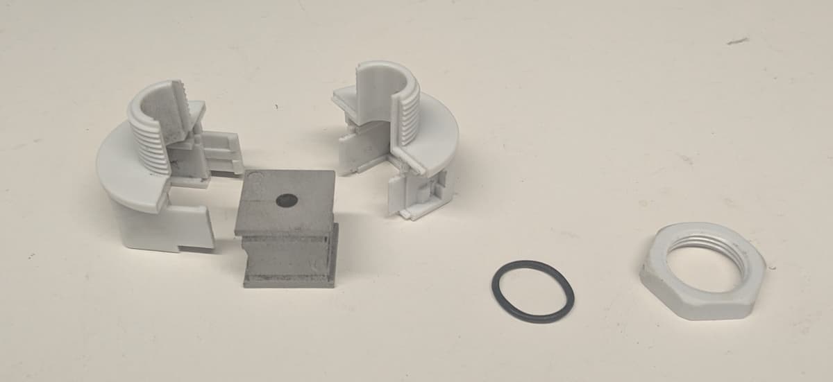
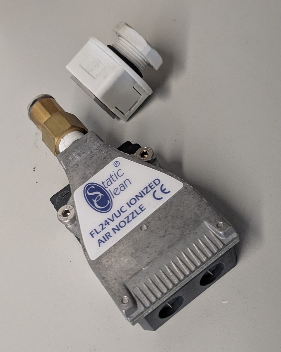
Remove the new ionizer, cable, cable clamp, and fasteners from the kit packaging. If they are installed, unscrew the nut from the cable clamp and slide the O-ring off the threads. Insert a slotted screwdriver or other similar tool into one of the two slots on the side of the clamp. Gently pry the clamp open. Repeat with the other slot on the other side of the clamp. Separate the two halves of the clamp and remove the insert in between.
Step 2: Secure the ionizer cable in the clamp

Step 2: Secure the ionizer cable in the clamp

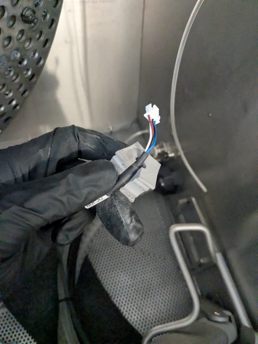
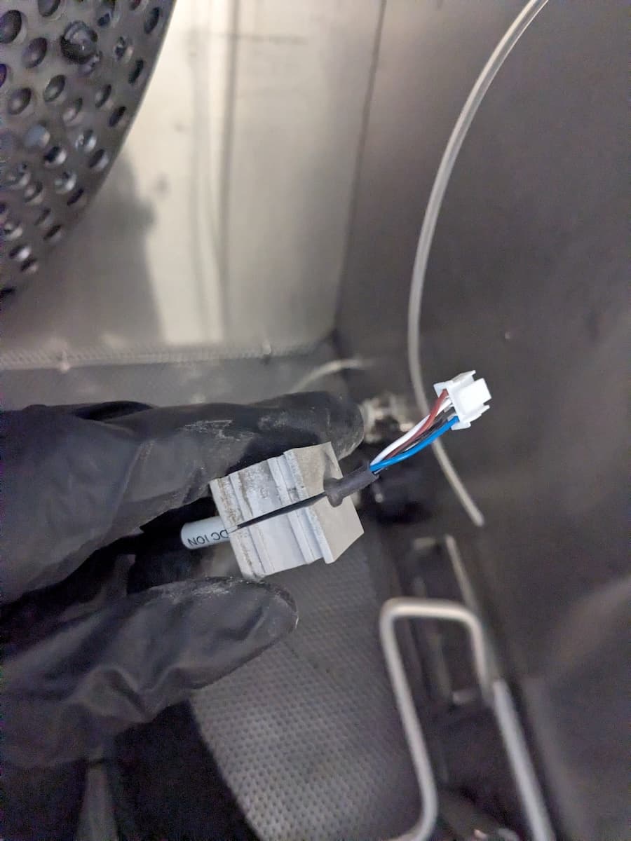
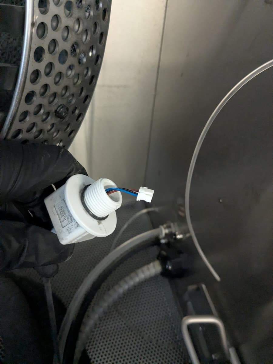
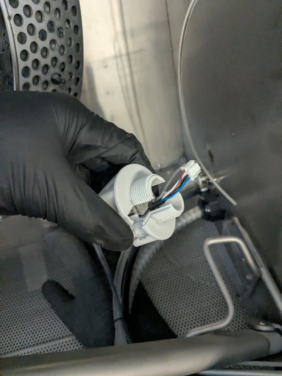
Gently open the cable clamp insert and insert the end of the new ionizer cable with the JST connector. Align the thicker portion of the cable with the front face of the clamp insert.

Place the insert into one of the halves of the cable clamp so that the JST connector extends out from the threaded section of the clamp. Place the other half of the clamp on top and squeeze it shut until it makes an audible click. Slide the O-ring over the threaded portion of the clamp.
Step 2: Secure the ionizer cable in the clamp

Step 3: Mount and secure the cable clamp

Step 3: Mount and secure the cable clamp

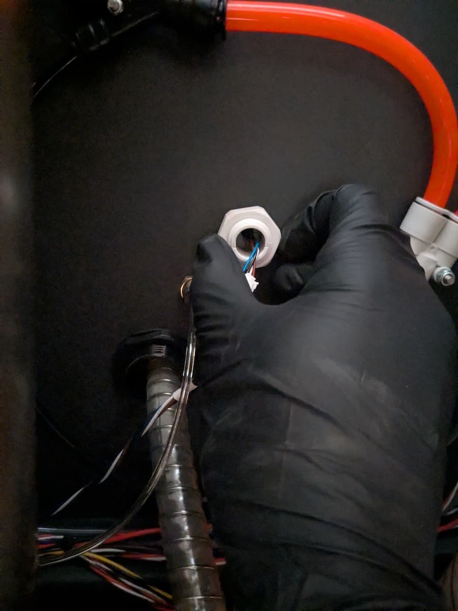
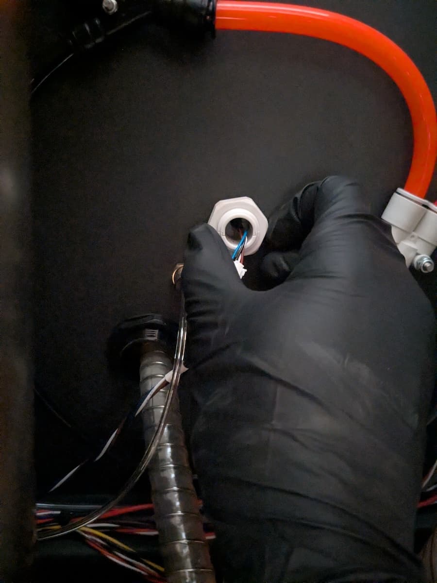
From the inside of the blasting chamber, insert the threaded portion of the cable clamp through the hole in the right wall of the chamber. Secure it with the cable clamp nut on the other side of the blasting chamber wall.

Step 4: Connect the ionizer cable to its extension cord

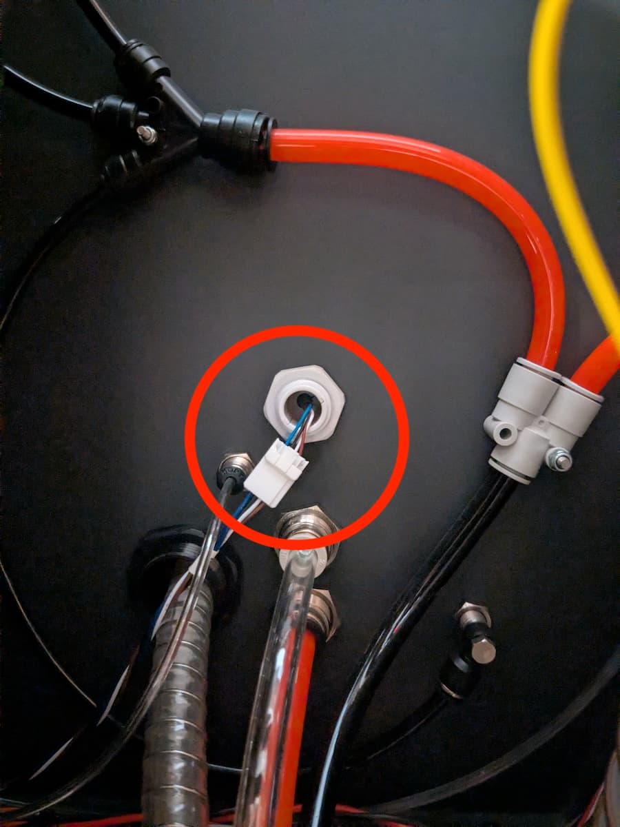
Connect the ionizer cable to its extension cable. The connectors only fit together in the proper orientation. Press the connectors together until the latch makes an audible click.

Step 3: Mount and secure the cable clamp

Step 5: Connect the ionizer cable to the ionizer

Step 5: Connect the ionizer cable to the ionizer

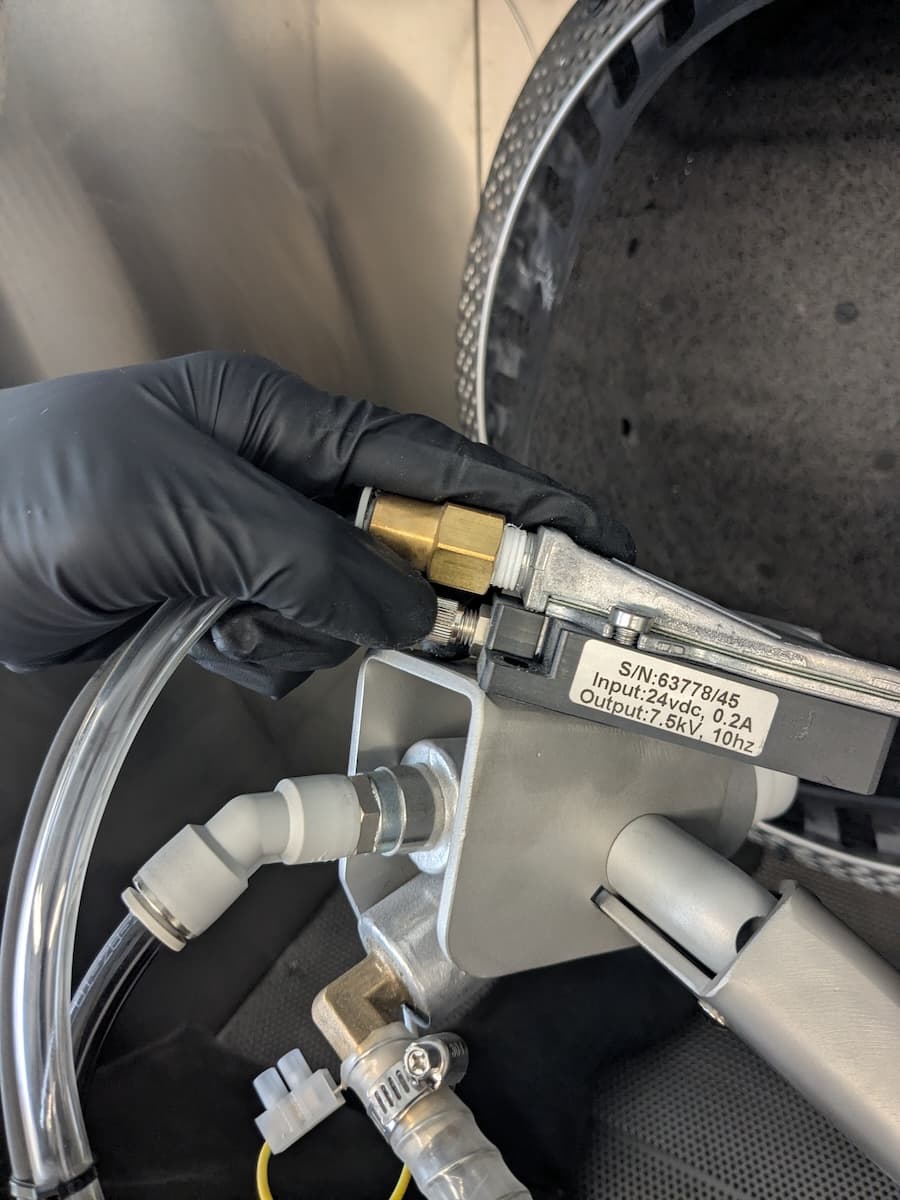
Orient the ionizer cable connector so that the four pins align with the corresponding holes in the port on the new ionizer. Plug the cable into the port, then tighten the threaded connector until the cable is secure.

Step 6: Mount and secure the ionizer

Step 6: Mount and secure the ionizer

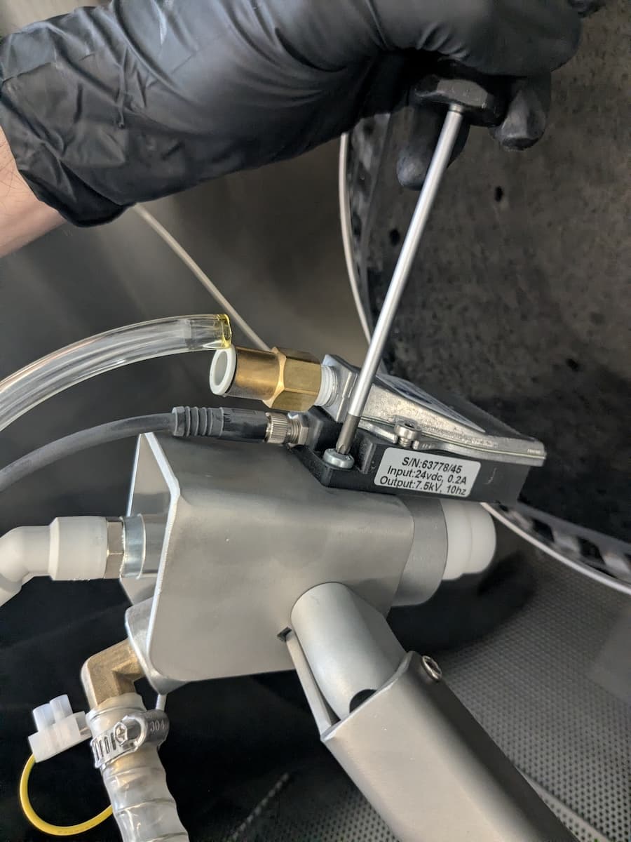
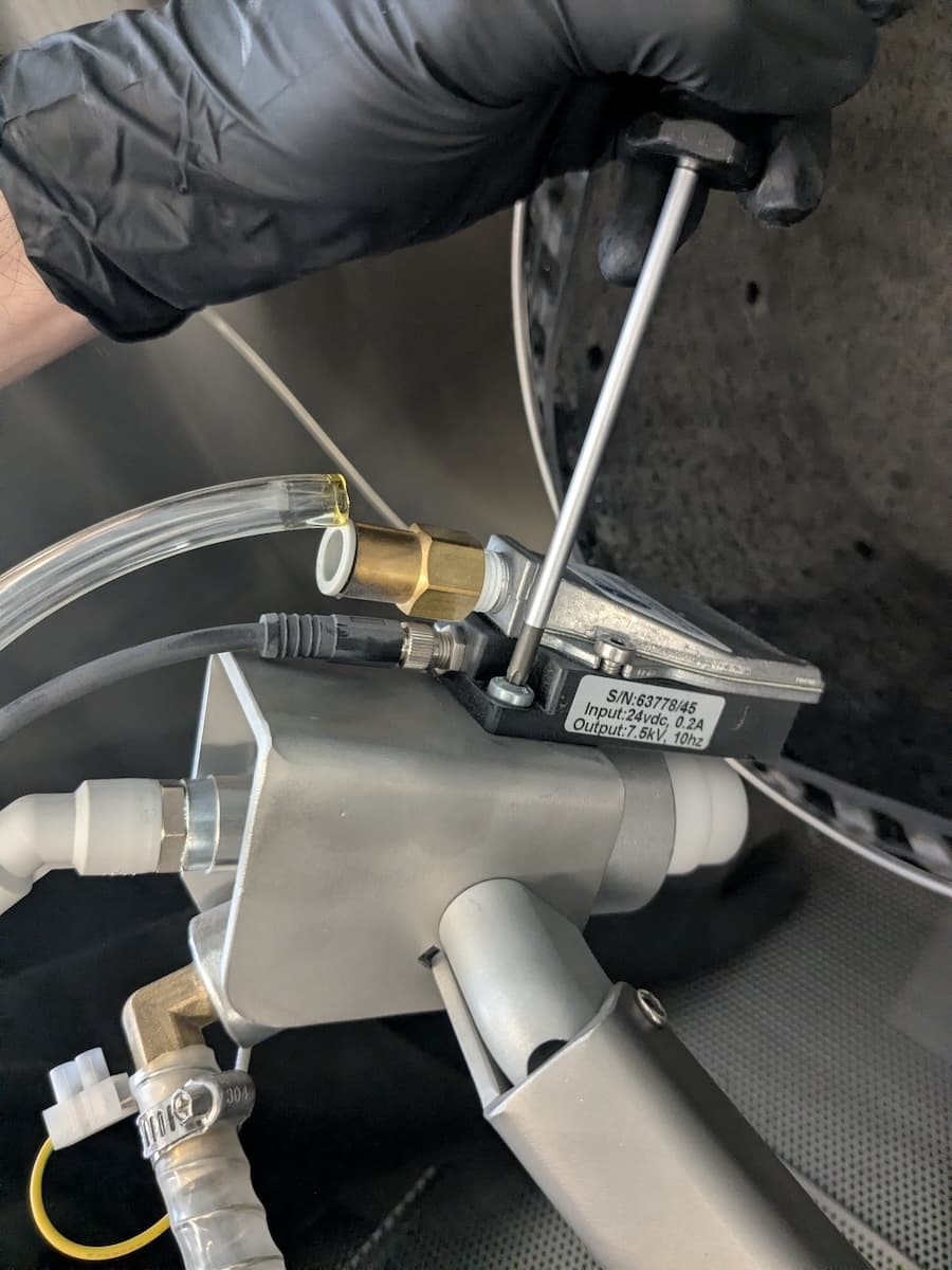
Place the ionizer on top of the blast gun, aligning the screw holes through the ionizer with the corresponding screw holes in the top of the blast gun. Thread one of the included Torx screws into both holes. Using a T25 Torx driver, tighten until snug.

Step 7: Connect the part rinse tubing

Step 7: Connect the part rinse tubing

Press the part rinse tubing into the push-to-connect fitting on the back of the ionizer.

Step 8: Route the ionizer cable

Step 8: Route the ionizer cable

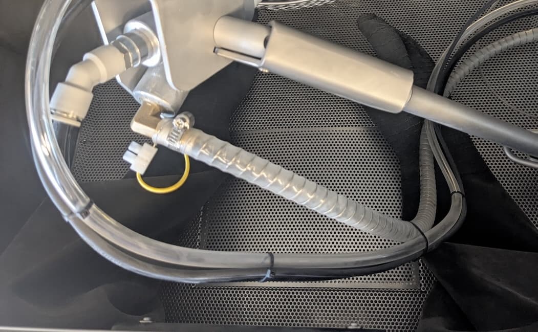
Secure the ionizer cable to the part rinse tubing with zip ties.

Reinstalling the upper sidecar panel

Overview: Reinstall and secure the upper sidecar panel.

Step 1: Remove the lower sidecar panel retention screws

Use a T20 Torx driver to loosen and remove any lower sidecar panel retention screws you previously reinstalled. Set the screws aside. Do not remove the two screws at the bottom of the lower sidecar panel.

Step 1: Remove the lower sidecar panel retention screws

Step 2: Mount the upper sidecar panel

Step 3: Remove the upper sidecar panel

Insert the upper sidecar panel horizontally such that the flange tucks under the upper panel. Rotate the sidecar panel downward, then tuck the lower flange under the lower sidecar panel.

Step 3: Secure the upper sidecar panel

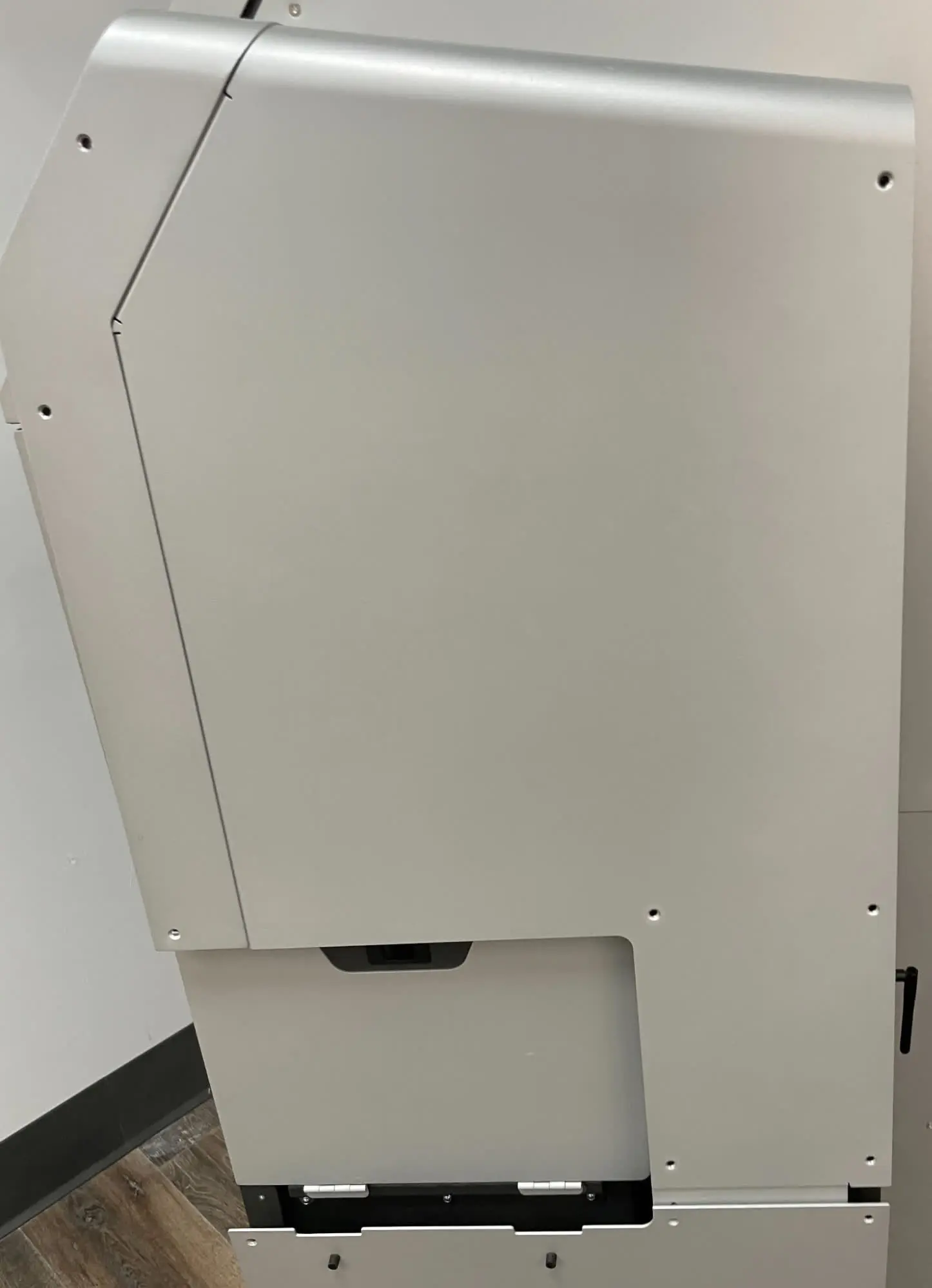
Thread one upper sidecar panel retention screw into each of the 12 screw holes in the upper sidecar panel. Use a T20 Torx driver to tighten until snug.

Step 1: Remove the upper sidecar panel retention screws

Step 4: Secure the lower sidecar panel

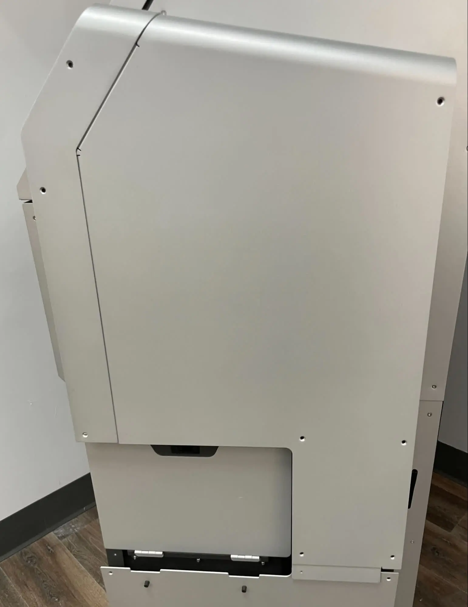
Thread one upper sidecar panel retention screw into each of the five open screw holes in the lower sidecar panel. Use a T20 Torx driver to tighten until snug.

Step 2: Remove the lower sidecar panel retention screws

Finalizing the repair

Overview: After replacing the ionizer and cable, power on the machine and perform final checks.

Step 1: Power on the machine

Connect the power cable to the machine and the power supply. Flip the power switch on the back of the machine to the ON position. The machine initializes.

Step 2: Test the ionizer

Test the machine to ensure that it operates normally:

  1. Close and latch the blasting chamber door.
  2. Rotate the blast arm and blast gun so you can see the back of the ionizer. Locate the LED on the back of the ionizer.
  3. Step on the air rinse pedal to activate the ionizer.
  4. Check the LED.
    • A green light indicates that the ionizer is functioning normally.
    • A red light indicates that there is an issue with the ionizer or its tips.
  5. Step off the air rinse pedal to deactivate the ionizer.