
How to 3D Print In-House Jigs, Fixtures, and Other Manufacturing Aids
For manufacturers, maximizing production speed while maintaining high part quality is critical for success. This white paper outlines the principles behind creating effective jigs, fixtures, and other manufacturing aids in-house, with an emphasis on leveraging 3D printing to reduce costs, shorten development time, and create more efficient production workflows from design engineer to manufacturing floor technician.
Introduction
Boost Efficiency With 3D Printed Manufacturing Aids
A manufacturing aid, also called a production aid or a production consumable, is any tool or device that supports and facilitates manufacturing operations from validation testing to production and maintenance. Manufacturing aids are used by businesses internally to make manufacturing and assembly processes simpler and more reliable, reducing cycle times, improving worker safety, and lowering production costs. They range from workholding devices such as jigs, fixtures, end-of-arm tooling (EOAT), and guides, to alignment pins, masking masters, and more. These are vital tools to streamline production workflows and address common problems that arise on the factory floor.
Typically, manufacturers machine tooling in metal (though sometimes in POM (Delrin) or other plastics) either in-house or through outsourced vendors. Machining requires expensive equipment and skilled labor for CAM settings and machine operation. Besides, most tools are made of multiple-part assemblies, adding complexity. Outsourcing comes with weeks of lead time and high costs. As a result, producing such tools customized and just-in-time can be challenging. Depending on the forces experienced by the part, however, it is not always necessary to produce these tools in metal.
Additive manufacturing (AM), also known as 3D printing, is a powerful solution to fabricate tools rapidly and at a low cost in-house. It is a toolless fabrication process that comes with some key benefits, such as speed, reductions in costs, design freedom, material choice, and flexibility.
Speed
3D printing allows you to produce internal tools rapidly and on demand, shorten lead times from weeks to days compared to outsourcing from vendors, and solve day-to-day production issues.

The traditional process of creating jigs and fixtures for most companies. If any issues are discovered after the jig or fixture is already in use, the process either needs to begin again, or the parts need to be reworked.

An additive workflow is much shorter. It generally requires little to no DFM work, and when production is done in-house, there is no need for quoting or days of transportation time for shipped parts.
Cost
Manufacturers can reduce material, labor, and equipment costs. Benchtop printers require very limited equipment and maintenance, saving CNC operators time for other high-value tasks in the meantime.
| Custom Jig | 3D Printed | CNC Machined |
| Lead Time | 5-9 hours | 2-3 weeks |
| Cost | $9-$28 | $45-$340 |
Looking at the cost comparison of Pankl Racing Systems' jigs production: in-house 3D printing is 48x faster and 12x cheaper than outsourcing milling.
Design Freedom
3D printing gives designers the freedom not only to introduce customization and print custom aids that match specific jobs but also to build complex geometries at no extra cost.
Advanced design tools have enabled engineers to create products highly optimized for end-use, but that same design freedom and increased part complexity make building jigs and fixtures more difficult. Traditional workholding systems like vises and clamps can’t secure and support amorphous shapes or parts with very fine details. 3D printing enables engineers to create objects without limitations like tool access and wear that come with machining. They can optimize geometries using ergonomic, latticed, or intricate shapes that would be difficult to manufacture with alternative methods. These methods also enable lightweight designs that extend the lifespan of a system because there's less weight to move around.
Additionally, leveraging 3D printing design possibilities allows manufacturers to simplify CAD models, decrease the number of parts, and reduce assembly needs on tooling.
Broad Materials Choice
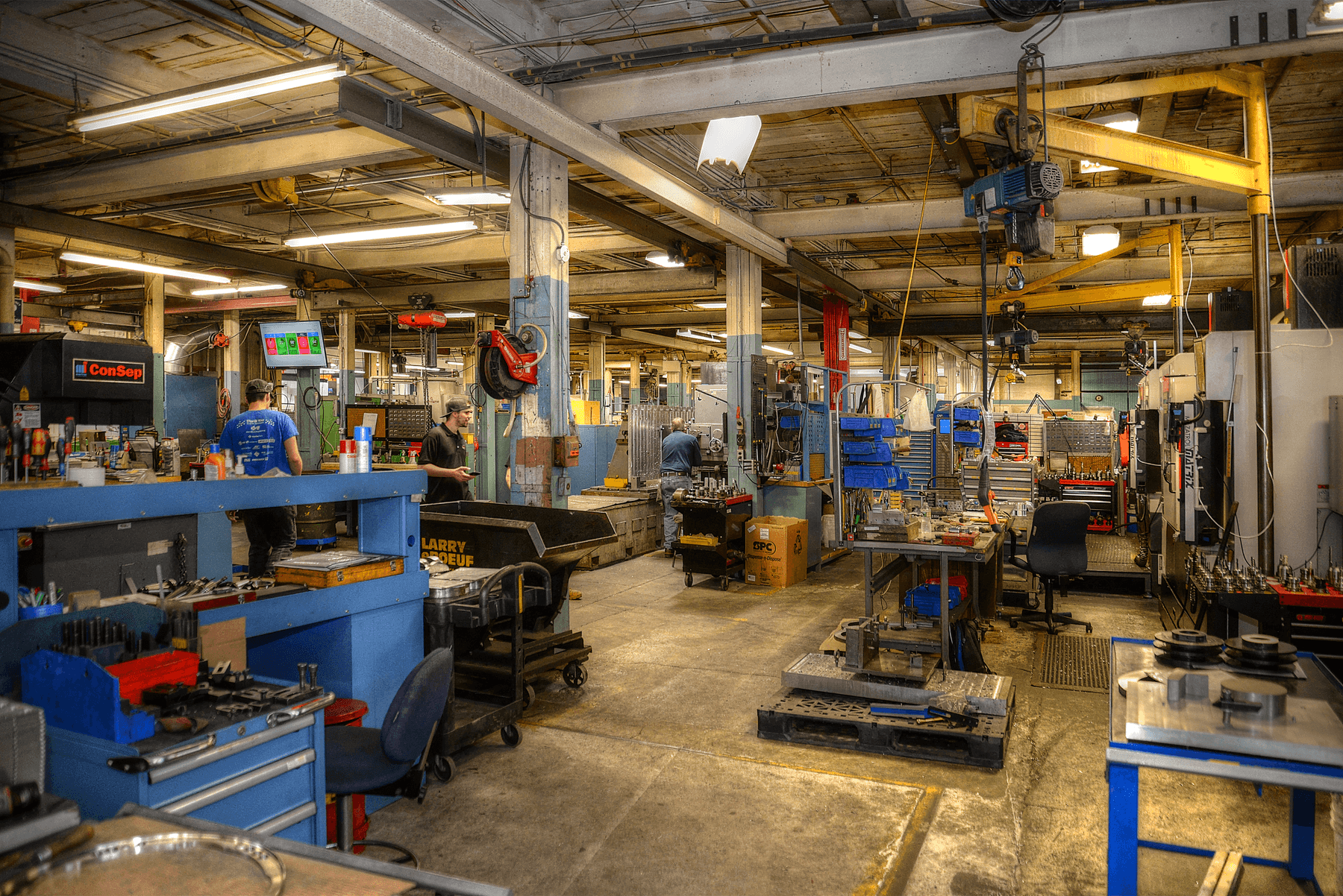
A&M Tool and Design’s machine shop includes a vast range of technologies, from Bridgeport CNC machines to a desktop SLA 3D printer.
With 3D printed jigs and fixtures, you can replace metal parts with lightweight and ergonomic 3D printed polymeric tooling, and diversify applications thanks to a wide range of 3D printing materials, from flexible to stiff or ESD-safe. Materials like Formlabs SLS Nylon 12 Powder mimic the material properties of familiar industrial plastics, like Delrin, making them an easy one-to-one swap.
Flexibility
In-house 3D printing brings the flexibility to create, revise, and iterate on solutions easily to ensure quality and increase operational agility. The technology enables you to:
-
Allow variations in your process and simplify tooling configuration.
-
Adapt tooling to production changes and 3D print spare, replacement, or stopgap parts on-demand to minimize machine downtime.
-
Encourage continuous improvements, move from physical to digital inventories, and change how the factory floor is organized.
-
Respond quickly to and rectify stoppages in production caused by broken or faulty manufacturing aids.
Can 3D Printed Polymeric Tools Replace Metal Tools?
3D printing has been ubiquitous in prototyping and product development for decades. Now, this maturing technology is entering widespread use in manufacturing. Recent advances in machinery, materials, and software unlock opportunities for producing high-precision, functional 3D prints that can replace metal tools and even stand in for end-use parts. Companies are already leveraging the flexibility of 3D printing for rapid tooling. Read Formlabs' guide to learn how polymeric tooling 3D printed with SLA can replace machined metal injection molds for hundreds of runs.
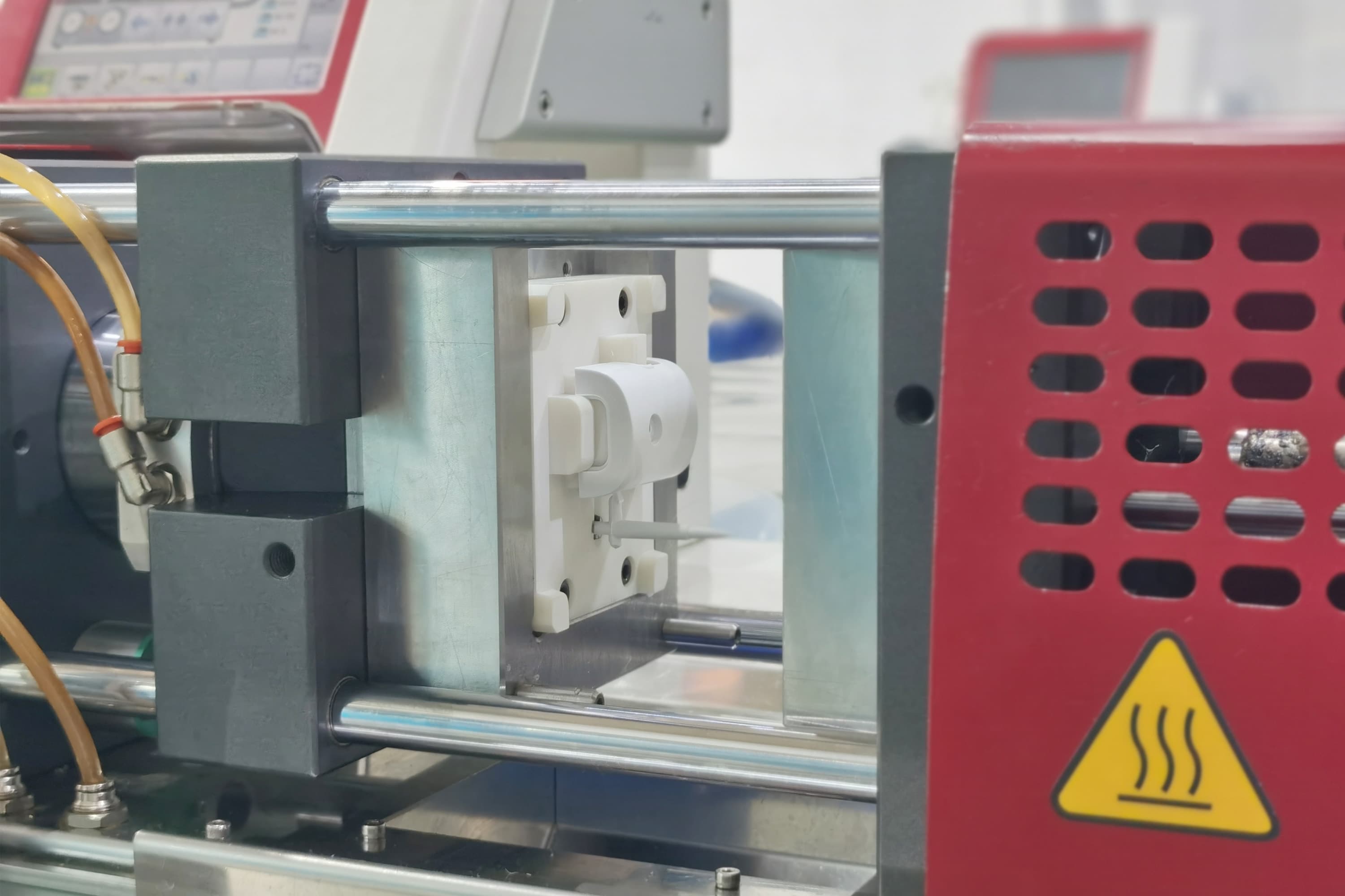
An injection mold insert 3D printed with Formlabs Rigid 10K Resin and installed in the Babyplast machine to inject hundreds of parts in PP, ABS and more (left). Marcus Marienfeld AG forms titanium parts with Fuse 1 3D printed Nylon 11 Powder press tools screwed into a toggle press (right).
Innovation doesn’t stop with tooling. Formlabs’ community is also producing end-use parts with both the SLA and SLS 3D printing ecosystems in order to unlock custom manufacturing and low-volume production. Read the results of stress testing run by Formlabs users to validate the performance of SLS 3D printed parts: from an aerospace supplier printing custom in-flight parts for aircraft, to a water metering devices manufacturer testing printed parts for 15 years of extreme weather exposure. Manufacturers around the world are using 3D printed polymeric tooling to replace metal parts or to repair defective equipment in automated machining operations, electronics or manual assembly lines, forming cells, foundries, and other production facilities.
This white paper explains the basic principles and concepts of fixture and jig design and discusses how to leverage the unique benefits of stereolithography (SLA) and selective laser sintering (SLS) 3D printing materials at every step of production to achieve lean manufacturing. Finally, it documents various user case studies of 3D printed aids to assist in the validation, fabrication, finishing, assembly, and inspection activities.
Methods
Common Types of Manufacturing Aids
Workholding Devices: Jigs, Fixtures, Soft Jaws, and More
Workholding devices locate, support, and secure the workpiece for a variety of manufacturing activities, including machining, welding, or assembly. They are often referred to as jigs and fixtures and are usually customized to closely match the unique geometry of a particular part.
A jig or guide holds the workpiece and guides the tool, while a fixture simply holds the workpiece. Common examples of fixtures are soft jaws, clamps, vises, chucks, or crankshafts.
Locating Devices: Alignment Pins and Locators
Locating devices, such as alignment pins, locators, or locator pins, are employed to position workpieces. They ensure the job is accurate and repeatable.
Protective Devices: Caps, Covers, and Masking Masters
Guards, caps, covers, or masking masters are used to preserve an element from a manufacturing operation. Caps prevent cross-contamination of holes during drilling, for instance. Masking masters ensure specific components of the workpiece are not covered by coating, dying, or other finishing efforts.
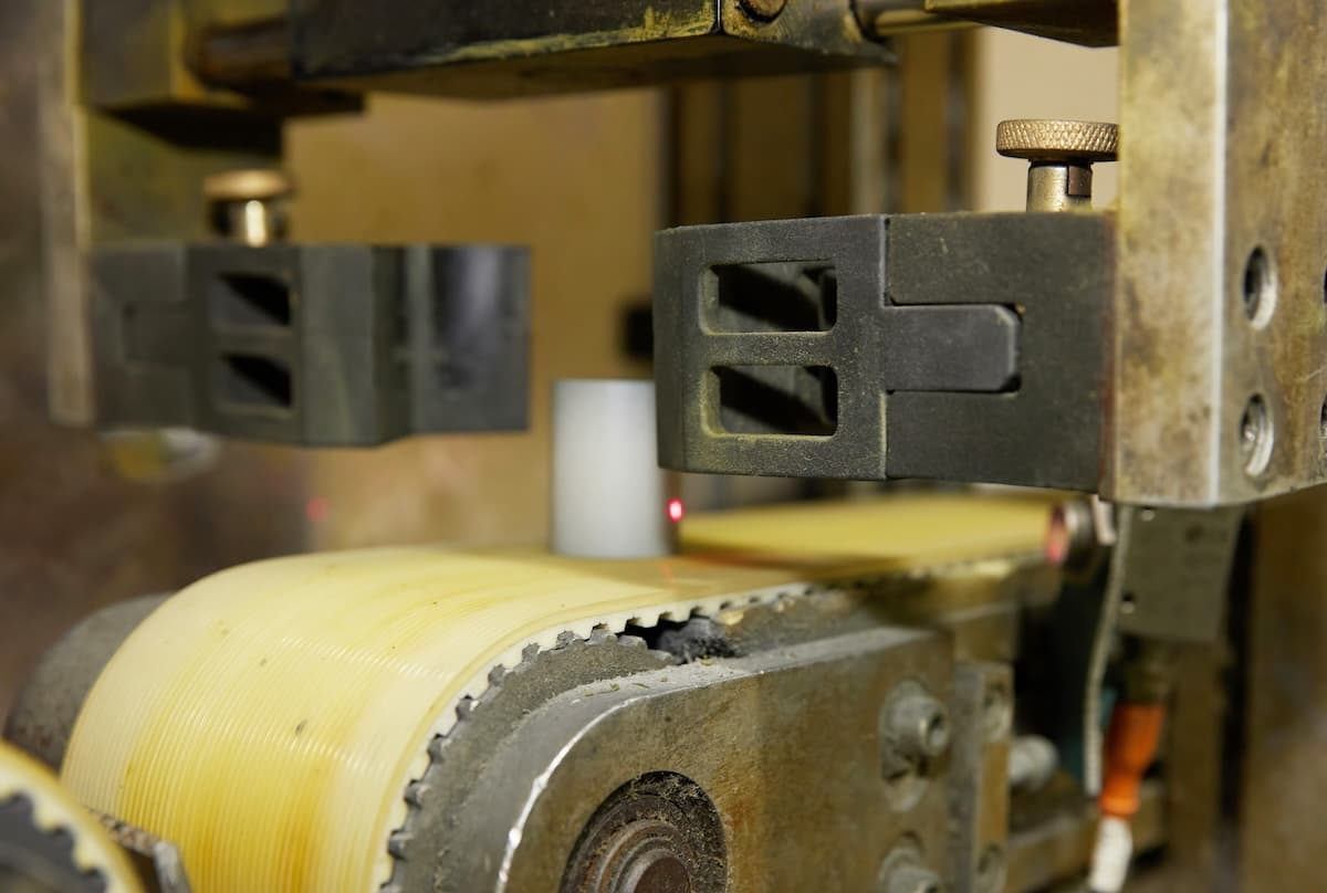
Measuring Devices: Gauges and Checking Fixtures
Measuring devices are used to determine a physical quantity. There are multiple types, ranging from a simple piece of material to complex machinery. In this category, gauges are popular to measure dimensions and check a workpiece against its allowed tolerances. In this image, a keyhole checking fixture is 3D printed on the Fuse 1 by Productive Plastics.
Machinery Components: Grippers, Connectors, Brackets, and More
From spider couplings to rollers, connectors, grip, grippers, and other end-of-arm tooling (EOAT), manufacturers often need to fabricate elements of their machinery on the factory floor. They are used for enabling a custom job, enhancing a machine, or simply replacing a defective item.
Organizers and Other Aids
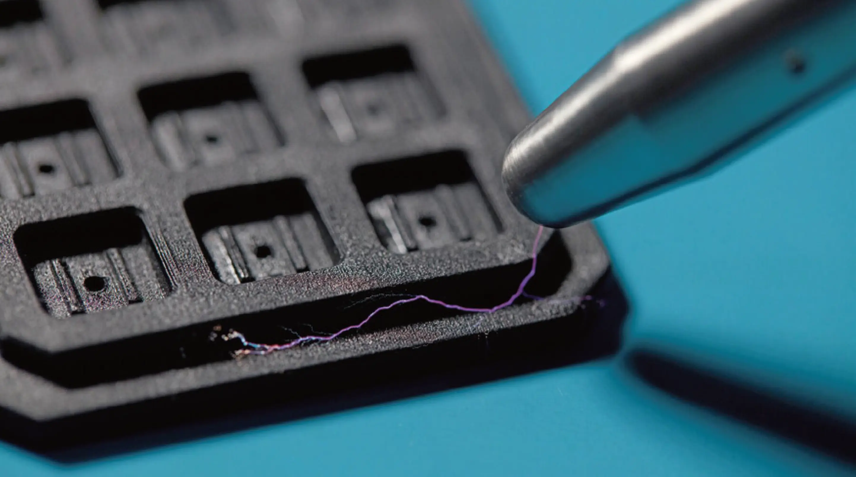
Organizers and other aids are any device that helps organize efforts on the factory floor (holders, brackets, mounts, adapters…), like this 3D printed circuit board that protects silicone chips against electrostatic damage.
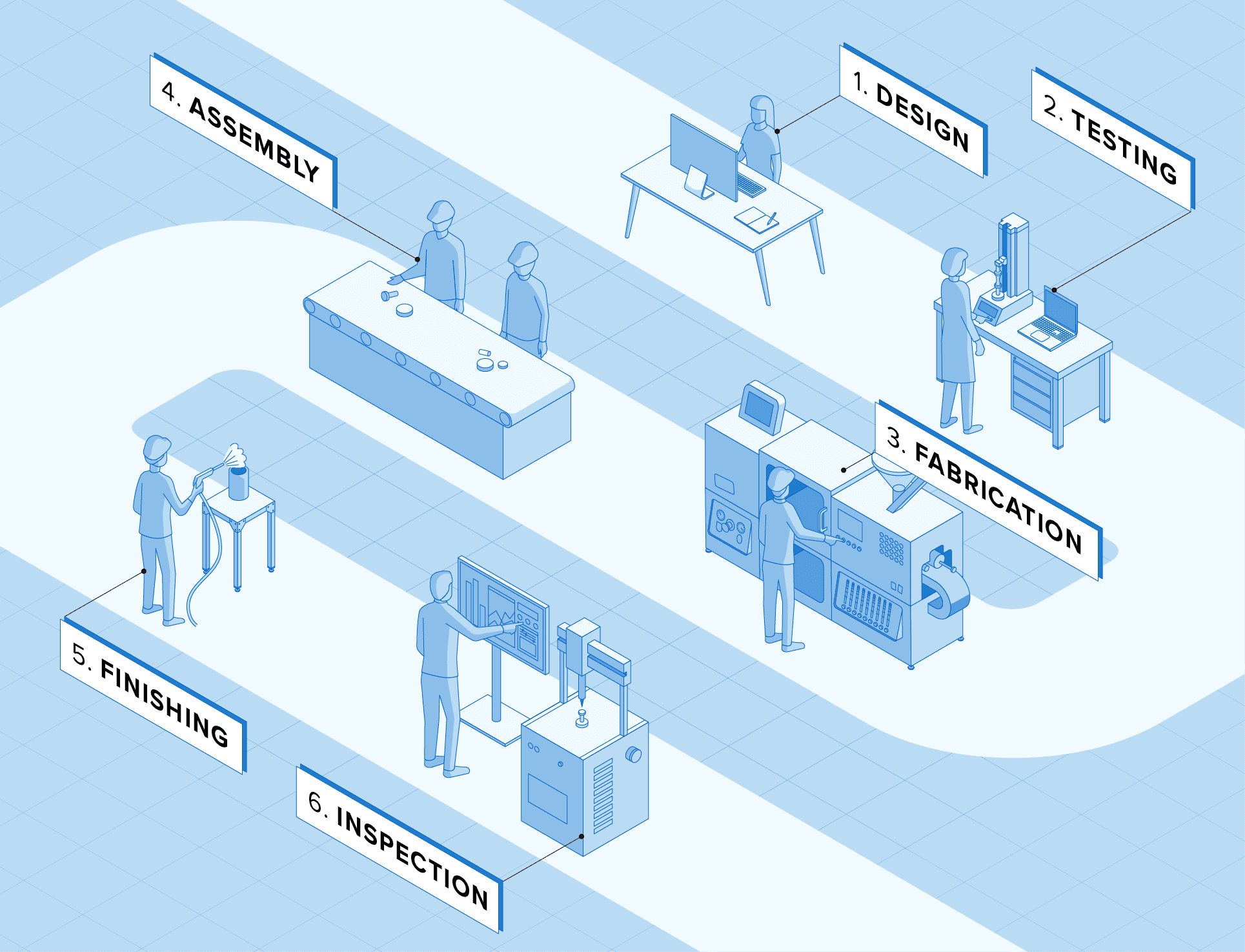
Workflow to 3D Print Manufacturing Aids
1. Design
Build a model of the part in CAD, respecting common design rules for additive manufacturing, or reverse engineer it with 3D scanning.
2. 3D Print
Upload the design into the print preparation software and 3D print it with the technology and material of your choice.
3. Post-Process
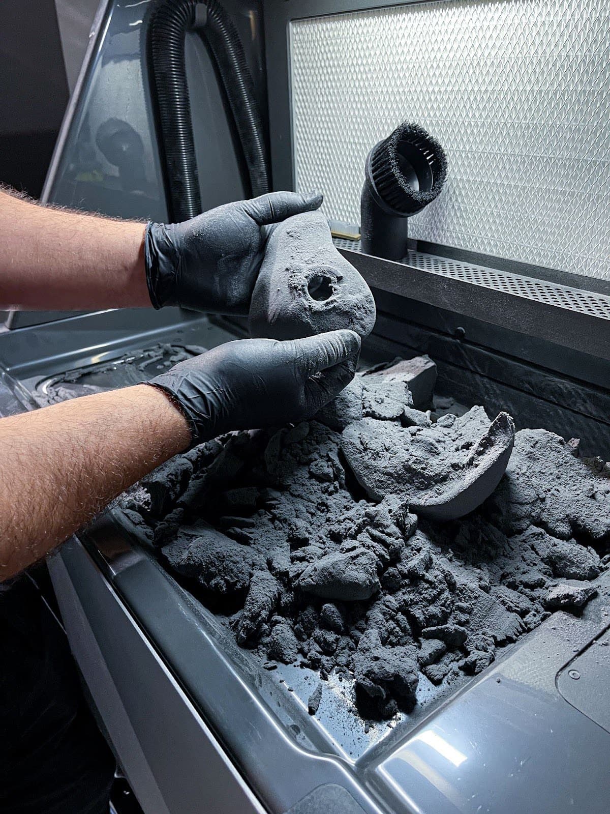
Finish the part according to the material specifications: wash and cure SLA parts or extract and media blast SLS parts, following Formlabs instructions.
4. Deploy
Validate your part. Integrate into your machine or manufacturing operation. Store the CAD file in a digital inventory and replace it as needed.
Design Guidelines
Design Basics: Degrees of Freedom and Constraints
In their most basic form, fixtures hold a part in a specific position while withstanding forces from a secondary operation, without the held part undergoing an unacceptable amount of deflection, movement, or rotation. To understand how this is achieved, one first needs to understand how degrees of freedom work. A rigid body in space has six degrees of freedom: up/down movement, left/right movement, forward/backward movement, and the ability to rotate along one or more axes, termed pitch, roll, and yaw.
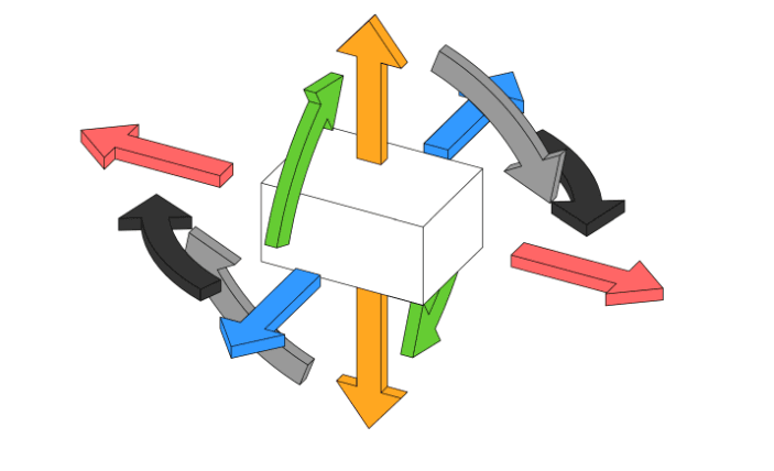
A part with all six degrees of freedom.
The principles of good fixture design require constraining those degrees of freedom as much as possible for accurate location and safety of secondary operations. It is equally important not to overconstrain the part. Excess constraints introduce unnecessary forces and accuracy problems by requiring higher precision across the fixture or jig. To explain this principle, consider a stool. A stool with three legs has just the right amount of constraint: when loaded with weight from its top surface, the stool cannot move vertically. Friction prevents the stool from sliding in any direction, and each leg is constrained by the others to prevent the rotation of individual legs or the entire stool.
-
Exact constraint is when there is one constraint for each degree of freedom required for correct operation.
-
Underconstraint happens when a part is free to rotate, shift, or slide in one or more directions or along one or more axes. In fixturing, underconstraint of a part prevents proper function and can pose a significant danger to machine operators and equipment. Depending on the application, however, some tasks may require underconstraint: e.g., a plank of wood that is free to move through a planer.
-
Undersupported parts have sufficient constraints to prevent shifting and rotation of the object, but not enough support to prevent the part from deflecting significantly during secondary operations like milling and drilling.
-
Overconstraint occurs when a structure has redundant constraints. One way to think of it is that when multiple forces work to do the exact same job, those forces come into conflict, and one of those forces will always “win” and end up doing the intended job. Redundant forces will in the best case do nothing, or in the worst case undermine the intended function of the structure, resulting in poor part quality and increased risk for the operator.
In practice, using “too many” constraints is sometimes necessary. A four-legged chair is an example of an overconstrained design. The fourth leg is redundant and introduces a new problem of rocking if it is resting on a surface that is even slightly uneven. The tradeoff is greater overall stability at the cost of a requirement for flatter floors. To put this in a manufacturing context, a more forgiving (less constrained) fixture design is useful to deal with parts that have more variation (like castings), while a tighter fixture will work better for parts with more precise surfaces (machined or injection molded parts).
Advanced design tools have enabled engineers to create products highly optimized for end use, but that same design freedom and increased part complexity makes building jigs and fixtures for secondary operations more difficult. Traditional workholding systems like vises and clamps can’t secure and support amorphous shapes or parts with very fine details. 3D printing allows engineers to create objects without limitations like tool access and wear that come with machining.
Design Best Practices
Increase Geometric Complexity
Since 3D printing allows for complex shapes at no extra cost, take some time to consider what additional functionality can be built into the jig or fixture at the design stage to take advantage of this principle.
-
Small features that would be difficult to machine, parts with curved or complex surfaces, as well as geometries considered impossible due to tool clearance in milling or turning, are all within the scope of additive processes.
-
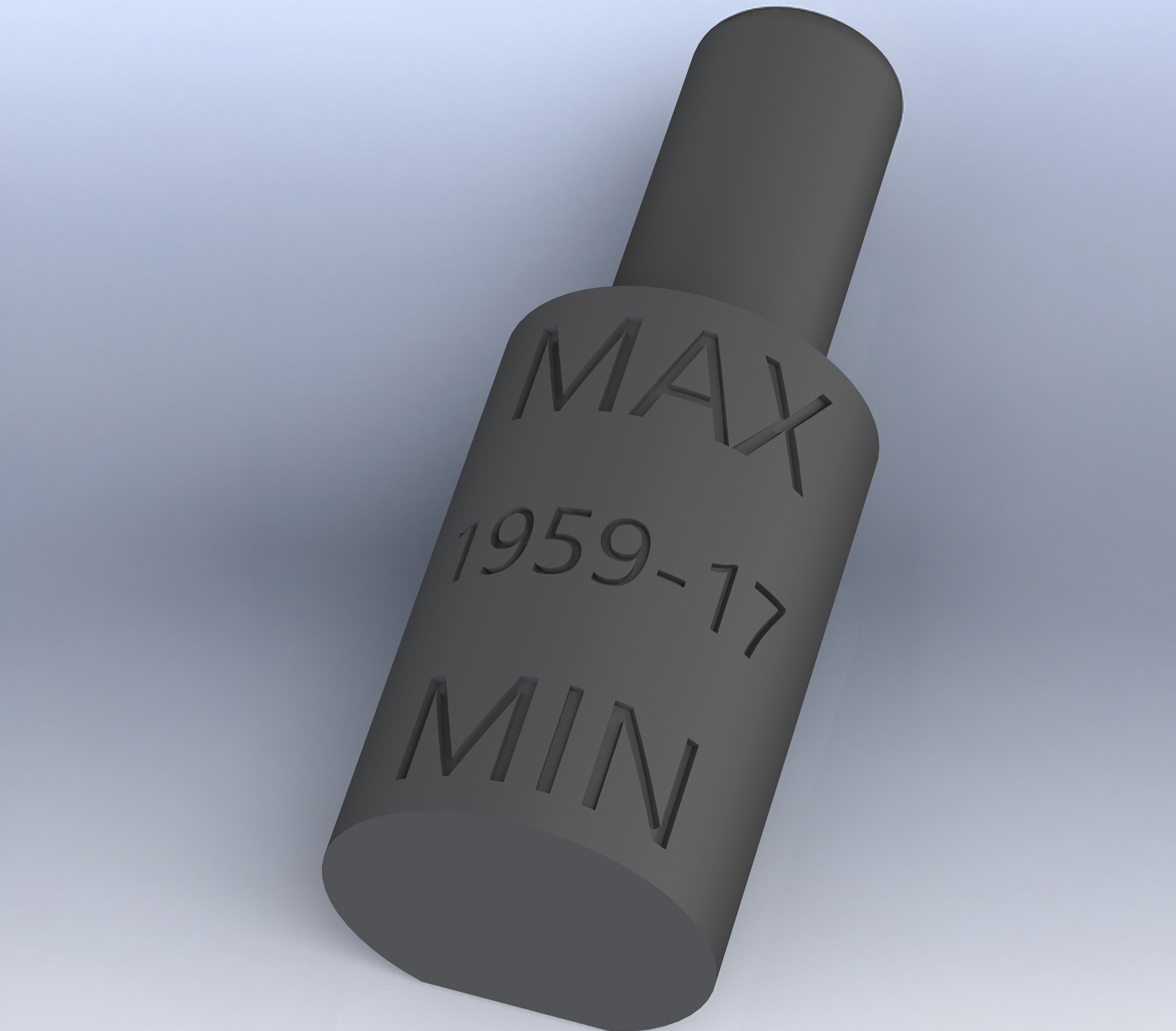
Serial numbers, fabrication dates, and other relevant data can be built into the part for digital inventory management and easy tracking without requiring secondary engraving steps.
Custom drilling jigs for complex geometries.
Reduce the Number of Parts
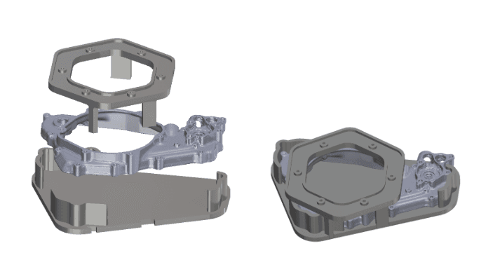
What would typically be two components in a machined fixture can be built into a single part, which helps prevent the buildup of dust or chips by eliminating gap space. For instance, instead of using inserted straight dowels or cylinders for part location, spherical or diamond-shaped structures are built into a single, gapless part. Using diamond or sphere-shaped locators reduces or eliminates the binding of parts during loading on and off by minimizing the contact area.
Build Datum Features Into Jigs and Fixtures to Facilitate Inspection
Part of the process of implementing jigs and fixtures in an assembly or manufacturing context is verifying the dimensional accuracy of the fixture. The amorphous part structures that 3D printed fixtures are often designed to address can mean that the fixtures themselves tend towards more esoteric forms. These designs can be difficult to inspect with standard metrology tools like calipers and micrometers. Building datum features into printed jigs and fixtures makes inspection easier and more accurate.
-
A datum is a theoretically geometrically perfect reference — a totally flat plane, the axis of a cylindrical hole, etc.. A datum feature is the reality of that concept in the context of the part, which is used as a principle reference point for other measurements. Datum features should be relevant to the requirements of secondary operations, and to the functional requirements of the part in end use.
-
Whenever possible, include flat faces or right-angle geometries within the fixture to aid inspection and determine overall accuracy. With any jig or fixture, accuracy is proven when inspecting parts after processing, as operating conditions like deflection in the part or tool can create errors requiring alterations to the fixture design.
-
In applications where precision is of utmost importance, use digital metrology tools like 3D scanners or touch probes to inspect more organic geometries.
Increase Rigidity With Reinforcing Ribs
The typical way to increase the stiffness of a machined fixture is to leave extra material in locations prone to bending under loading. In additive processes, minimizing material consumption keeps part costs low and speeds up the printing process. Using reinforcing ribs and fillets provides additional structure without dramatically increasing the cost or build time of the part.
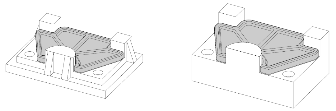
A typical 3D printed geometry for maximizing stiffness and minimizing material usage (left) and a typical milled geometry for minimizing material removal and machining time (right).
Increase Durability of Mechanical Connections With Threaded Inserts
Using tapped holes in 3D printed plastic parts is an ineffective method for joining parts for fixturing; these parts are more prone to breakage or wear with repeated use than metals. Instead, use more resilient assembly methods, like threaded inserts or a pocket to restrain a nut while a bolt is tightened. Alternatively, a 3D printed fixture may have clearance holes to run bolts through to T-nuts or a fixture plate below. To prevent elastic deformation of the part when bolted down to the work surface, through holes should use clearance-fit tolerancing.
Consider User Experience When Designing Tools
A successful manufacturing operation takes into account not just how parts are processed with jigs and fixtures, but also how workers mentally and physically experience the tools they use. While every application carries different considerations and trade-offs, a few common concepts will reduce labor pains and improve performance:
-
Whenever possible, design jigs and fixtures to operate with one hand, freeing the other hand for part positioning, stabilizing, or resting during changeover.
-
Design the fixture or jig for secure holding of the part during secondary operations without human assistance.
-
Use geometries that magnify placement errors to make misalignment obvious.
-
Consider not just the part in the context of the fixture, but the overall flow of work, from loading in the part and performing secondary operations to removing the part and sending it onto the next station. Always strive for the fewest steps required to operate the jig or fixture to keep cycle time and fatiguing worker motion to a minimum. Pantomime the steps involved while designing to make sure all necessary motion and spatial affordances are included.
Make Allowances to Manage the Effect of Machining Debris
When drilling a hole, for example, a small burr will be created. Leaving a gap space within the jig allows space for a burr to form without interfering with the part or tool operation. Similarly, with milling operations, small chips of material can accumulate on the jig or fixture. Whenever possible, minimize or eliminate small gaps, grooves, and pockets where chips can become wedged. Creating recessed channels improves the function of the fixture or jig, allowing stray chips to fall out of the path of the part during loading and unloading. Rounding corners and grooves creates ramped surfaces, easing sweeping, blowing, or washing away debris from the work area. Milling surface fillets is time-consuming and costly, requiring either extensive material removal or an assembly of parts that introduces new seams.
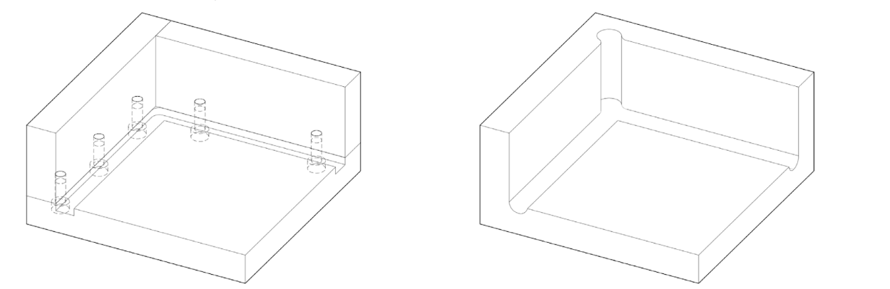
A typical milled and assembled corner locator, composed of three bolted plates, creates more opportunities for chips to become wedged (left). A typical geometry for a 3D printed corner locator with eased edges, smooth relief pockets, and no seams, all without increasing the cost of the part (right).
3D Printing Guidelines
Over the last few years, high-resolution 3D printers have become more affordable, easier to use, and more reliable. As a result, 3D printing technology is now accessible to more businesses, but choosing between the various competing 3D printing solutions can be difficult. Read this technology guide to compare the three most established 3D printing technologies: fused deposition modeling (FDM), stereolithography (SLA), and selective laser sintering (SLS).
3D printed jigs and fixtures are often fabricated with FDM because it is fast, easy to use, and low-cost. However, SLA and SLS are better suited for manufacturing aids that require:
-
Higher resolution, better accuracy, and a smoother surface finish
-
Superior mechanical characteristics, such as strength and durability
-
Complex designs
-
Higher throughput
Producing Manufacturing Aids With SLA Printing
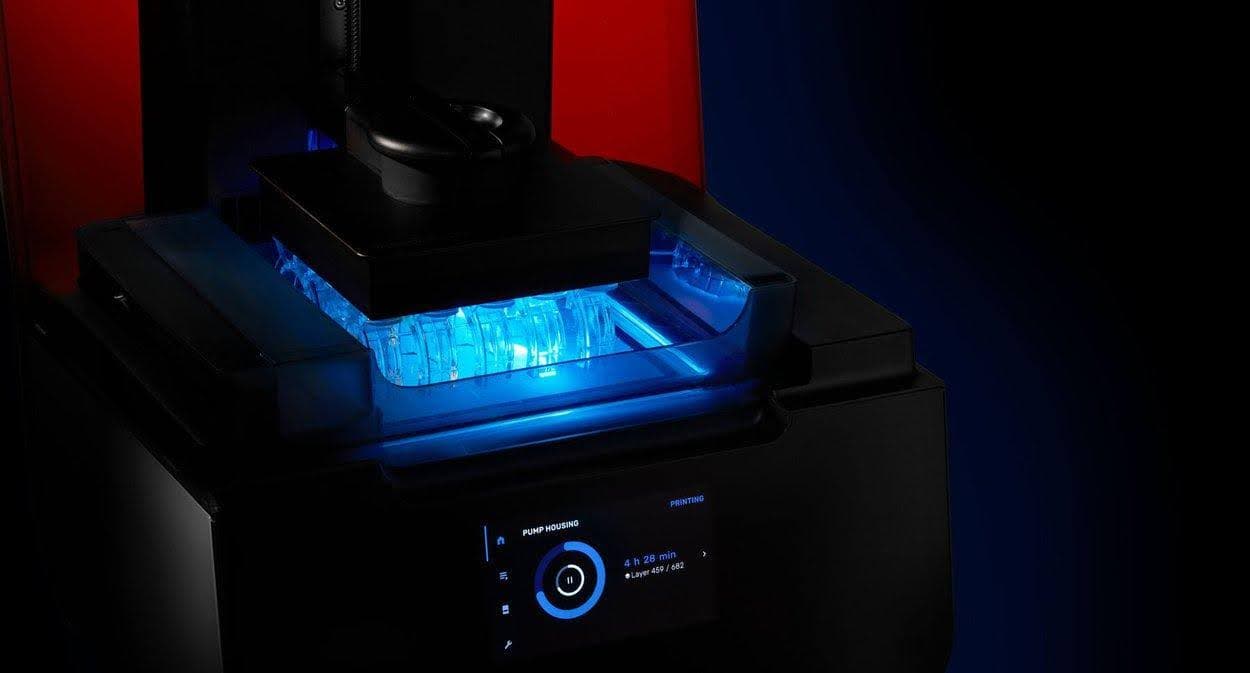
SLA resin 3D printers use a laser to cure liquid resin into hardened plastic in a process called photopolymerization. SLA parts are isotropic and have high resolution and accuracy. Choose this technology for clear details, a smooth surface finish, and a wide range of material choices.
From flexible to stiff, ESD-safe, or temperature-resistant, Formlabs offers a portfolio of engineering resins with advanced properties that enable applications in demanding environments. The family of Tough and Durable Resins is particularly popular for 3D printing jigs, fixtures, and other aids.
Formlabs SLA 3D printers are easy to set up, operate, and maintain. They require minimal equipment and can be seamlessly integrated into any production workflow. SLA parts, however, have limited strength and durability. For printing long-lasting tools, SLS technology is recommended.
Producing Manufacturing Aids With SLS Printing
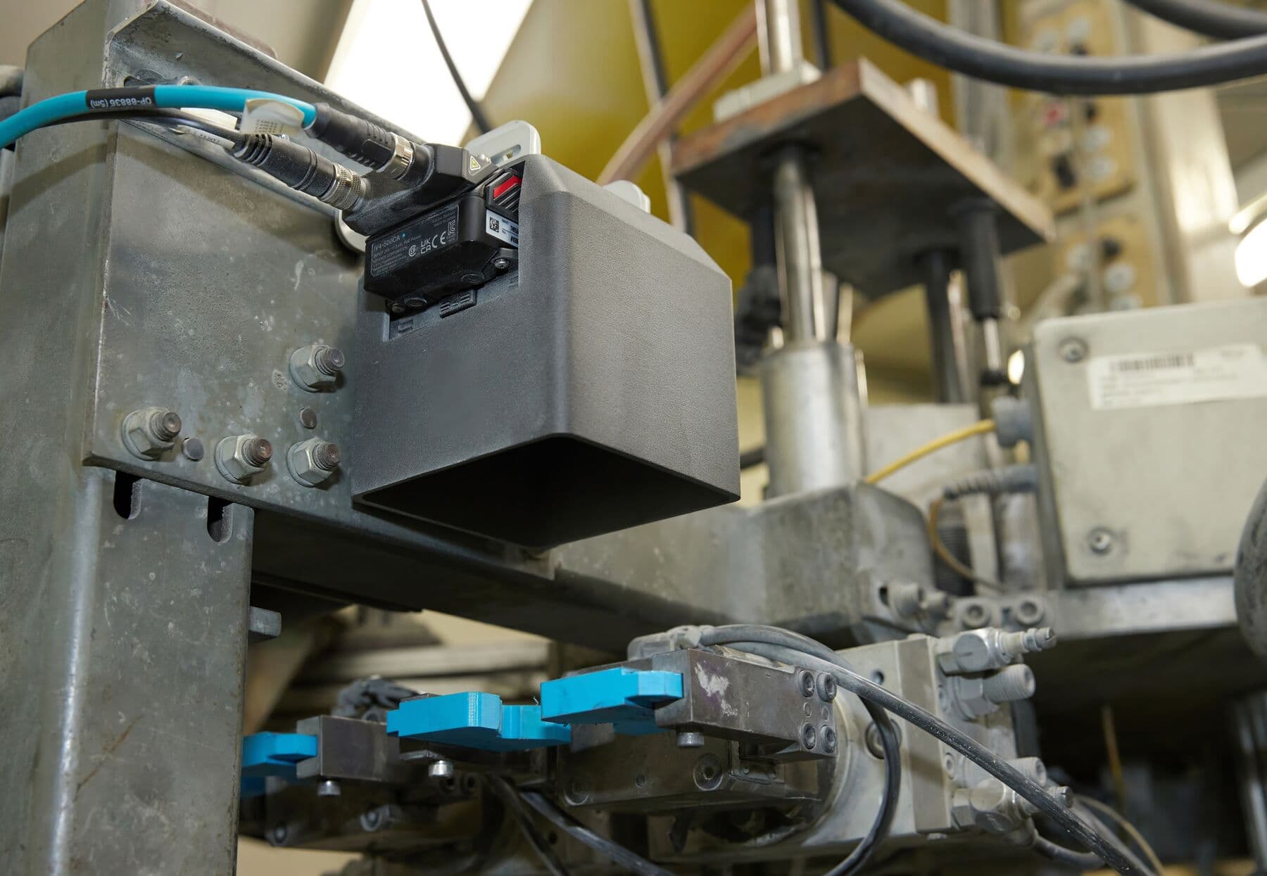
This camera enclosure, designed and printed by Eaton, was printed on the Fuse 1+ 30W in Nylon 12 Powder and protects AI cameras from excess light that could throw off the accuracy of their readings.
Selective laser sintering (SLS) is the most popular additive manufacturing technology for industrial applications and is commonly employed for end-use parts production. Choose SLS technology for producing functional, durable tools with complex geometries at high throughput.
While SLA is a resin-based process, SLS 3D printers use a high-powered laser to fuse small particles of polymer powder. The unfused powder supports the parts during printing and eliminates the need for dedicated support structures. This makes SLS ideal for complex geometries, including interlocking links, functional assemblies, and living hinges.
One of the main advantages of SLS is the materials. SLS 3D printing materials, such as nylon, are already commonly used in design, engineering, and manufacturing, whether through injection molding, machining, or additive manufacturing. Nylon parts are strong, durable, temperature-resistant, and long-lasting, making them ideal for manufacturing aids. The final parts are impact-resistant and are ready to undergo the rigor of the factory, enduring repeated wear and tear from daily production activities.
Formlabs’ Fuse Series ecosystem is a compact, contained solution that packs industrial power at a fraction of the cost of traditional SLS 3D printers. Bringing SLS in-house means businesses can control a greater portion of their manufacturing processes.
Choosing the Right 3D Printing Technology
The following table summarizes some key considerations to choose between SLA or SLS for 3D printing manufacturing aids. Check out Formlabs’ in-depth technology comparison for more details.
SLA 3D Printing - Form Series
-
Fine details and smooth surface finish
-
Wider range of materials
-
Easier to use
-
Lower hardware costs
SLS 3D Printing - Fuse Series
-
Sturdy, stable, and long-lasting tools
-
No supports, better suited for complex designs
-
Higher throughput
-
More cost-efficient for large production
Workflow Best Practices
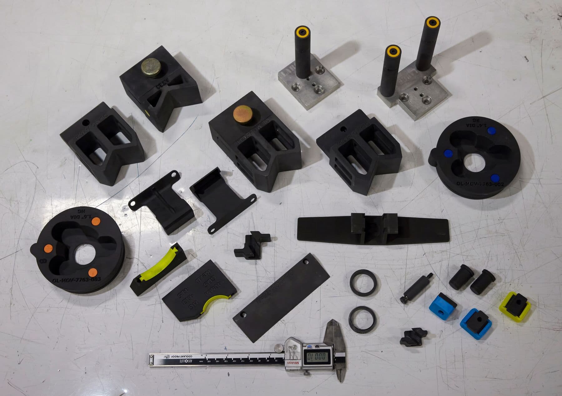
Eaton's Olean plant SLS 3D prints hundreds of manufacturing aids every year. These are some of them, including robotic EOAT, grippers, part movers, enclosures, spacers, and more.
Validate the Printed Tool
-
Inspect the printed part against the original CAD model. Use a caliper, micrometer, or other metrology equipment to check the dimensions of the print against its theoretical value.
-
Test the functional performance of the fixture. When the part is loaded onto the fixture, pay close attention to how well it is seated against locating surfaces and supports. A properly designed and built fixture will support the part, eliminating any movement once clamping force is applied.
-
For processes with higher operating forces, like milling or drilling, calculate clamping requirements based on feeds and speeds, the power of the machine, and the selected material, as well as safety.
Consider Creep When Printing With SLA
Some 3D printing materials, in particular SLA resins, experience creep (permanent elastic deformation) if continually loaded, as in the case of a printed fixture clamped to a work table for long periods of time. To avoid the warping of parts due to continued loading, it’s best to loosen any bolts and relieve clamping forces after completing secondary operations. If your parts will experience continuous load, we recommend printing them with SLS technology instead.
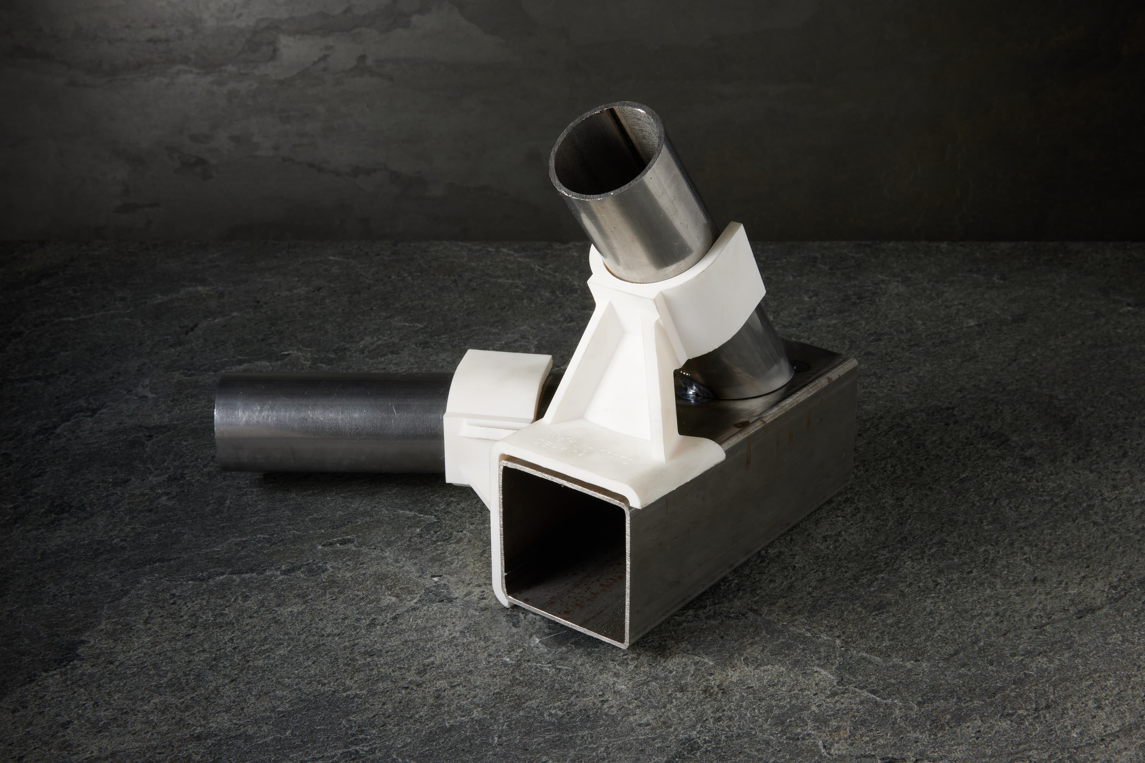
Augment 3D Printed Tools Using Common Stock Parts
This approach works well when some components need the specificity and design flexibility of 3D printing, but the overall working envelope or other requirements like stiffness or conductivity cannot be met through an additive process. Common stock parts to add extra functionality to printed jigs and fixtures include metal shaftings for spanning greater distances while maintaining rigidity, or washers for distributing screw clamping loads over a larger footprint. Stock parts in combination with additive processes quickly add mechanical functionality like linear or rotary indexing at a much lower cost than machining the whole tool.
Assist Tool Ejection
Use springs, ramped slides, or levers to raise the part up from the fixture surface. By placing springs into the fixture, when the clamping force is removed the part will be brought up away from the surface of the fixture, giving the operator easier access for part removal. The same can be achieved with a movable slider or lever, though with an additional step required by the operator. Determining the right approach depends on the application, the tooling setup, and cycle time requirements.
On-Demand Replacement for Wear Components
Even under normal usage conditions, fixtures, assembly tools, and jigs commonly become broken or worn to the point where they are no longer effective. By creating jigs and fixtures with additive fabrication, a facility takes control of its own production and gains the ability to replace tools on-site on an as-needed basis, rather than counting on external vendors with minimum order quantities. Replacing worn fixtures with in-house equipment shortens the supply chain and reduces downtime risk.
Post-Process 3D Printed Tools to Enhance Material Properties
SLS materials can go even further in performance and appearance when paired with advanced post-processing methods. Read our SLS guide to learn about both the basics of post-processing SLS 3D Printed parts and advanced methods such as media blasting, smoothing, coating, coloring, and more. Post-processing and finishing methods such as electroplating or coating can also be applied to SLA parts to enhance strength and durability.
Case Studies
This section documents various cases of manufacturing aids developed by Formlabs SLA and SLS 3D printer users for each step of the manufacturing process, from validation testing to inspection.
Validation Testing
3D printed gauges and test fixtures can assist the validation process, even before going to production. Validation is the process of determining whether a piece of hardware complies with the requirements set upon it and is ready for production. The goal of the validation stages is to ensure that the product can be manufactured consistently at scale. It is an extensive set of tests that occur at the last step of product development on prototypes and pre-production parts.
Testing methods include environmental chamber tests, thermal cycles, vibration, ESD, biocompatibility, chemical resistance, certifications such as FDA, FCC, UL, CE, EC, and RoHS, aging, radiation, cosmetic, wear, and drop tests, among others. The on-demand 3D printing of testing tools allows manufacturers to accelerate the testing procedure and iterate quickly on prototypes and pre-production parts.
Test Fixtures
Company: Dorman Products
Dorman Products, a century-old manufacturer of aftermarket automotive parts, is using SLA and SLS 3D printing to speed up their production timelines and increase quality. Here, SLA 3D printed test fixtures in Tough 2000 Resin are designed to replicate the conditions that aftermarket components will face in an automotive environment. With 3D printing, these tests don't require a full-scale car to ensure the functionality and quality of Dorman's parts.
Radiator Mating Geometry Simulation Fixture
Company: Dorman Products
This customized test fixture is made to simulate the mating geometry for the same pressurization test. Having a 3D printed test fixture like this eliminates the need to use a full-size radiator in order to conduct the test. Before 3D printed test fixtures, to test a component properly, the Dorman team needed to create the exact setup the parts would face in the real world, often using full-scale automotive parts.
Holding Cups
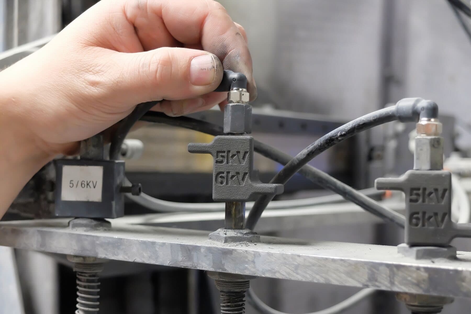
Company: Eaton
Previously machined from Delrin, these tester cups hold the MOVs during the electrical testing phase, where voltage is shot through the parts to ensure performance when they’re assembled into full surge arrestors. They are needed in high volumes and for different-sized MOVs, which are identified by small colored FDM TPU inserts in the tester cups.
Welding Set-Up Fixture
Company: Brose North America
Welding robots at Brose NA have to switch programs between different product lines multiple times a day. Each time the robot switches to a new product line, the welding department has to reprogram its parameters. 3D printed set-up fixtures offer a fast and inexpensive solution. This SLA 3D printed set-up fixture was printed in three hours on Form 4L in Tough 2000 Resin.
Fabrication
Fabrication is the process of shaping raw materials into an item. Fabrication techniques include forming, molding, casting, machining, or welding. They typically require specific, expensive machinery, such as a computer numerical control (CNC) mill, tooling, and skilled labor. Optimizing the throughput of such machines is fundamental to recovering production costs and growing return on investment (ROI). Thanks to in-house 3D printing, manufacturers can produce low-cost custom jigs, fixtures, soft jaws, alignment pins, and other aids tailored to their specific fabrication approach and workflow.
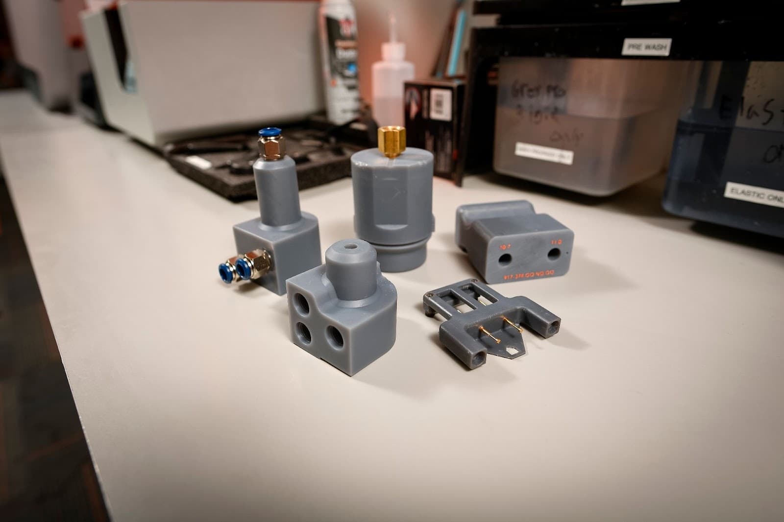
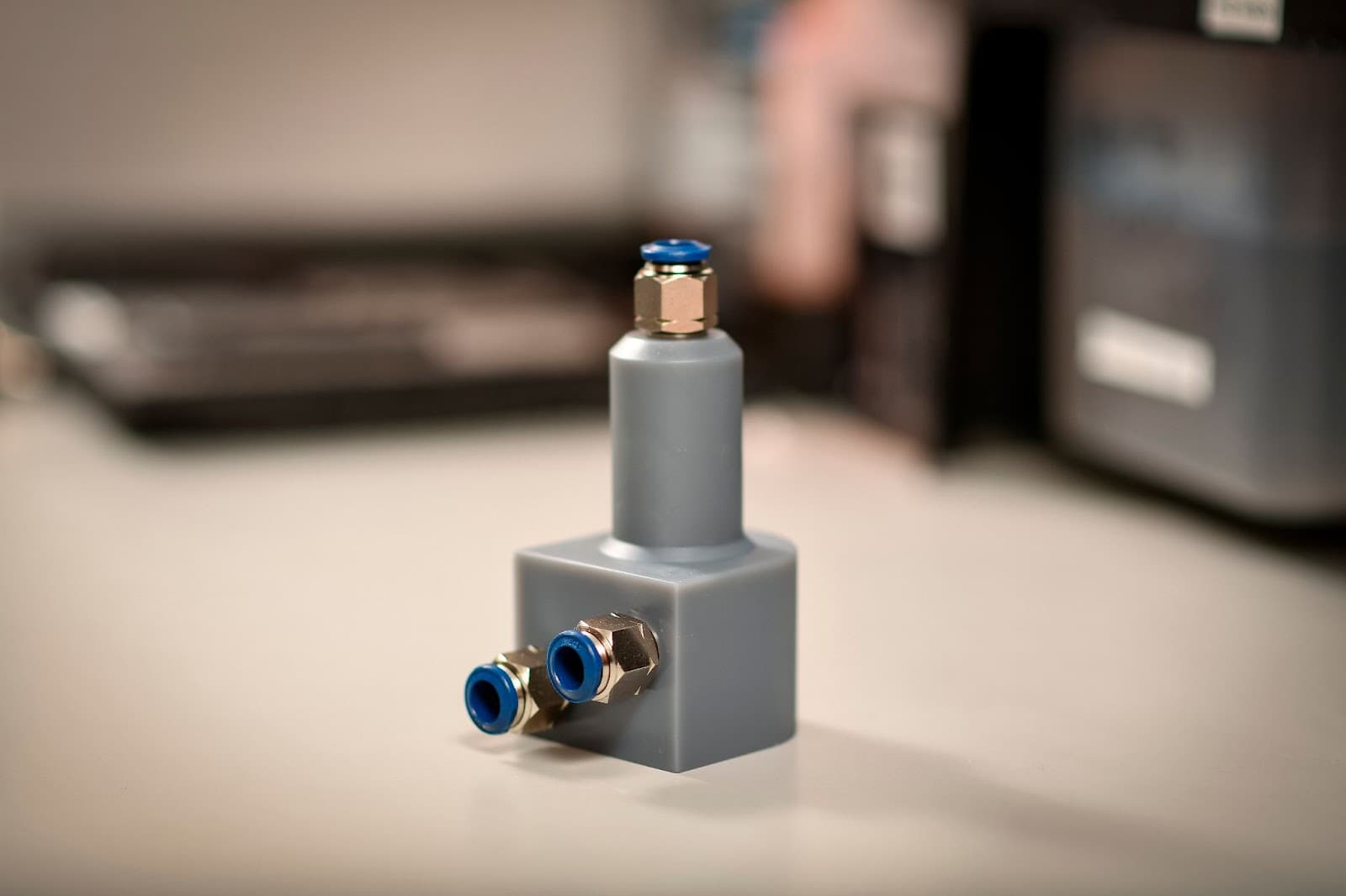
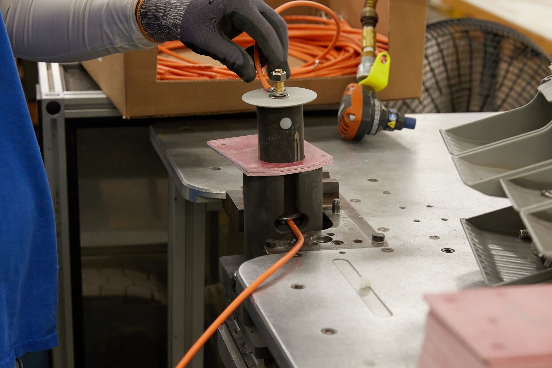
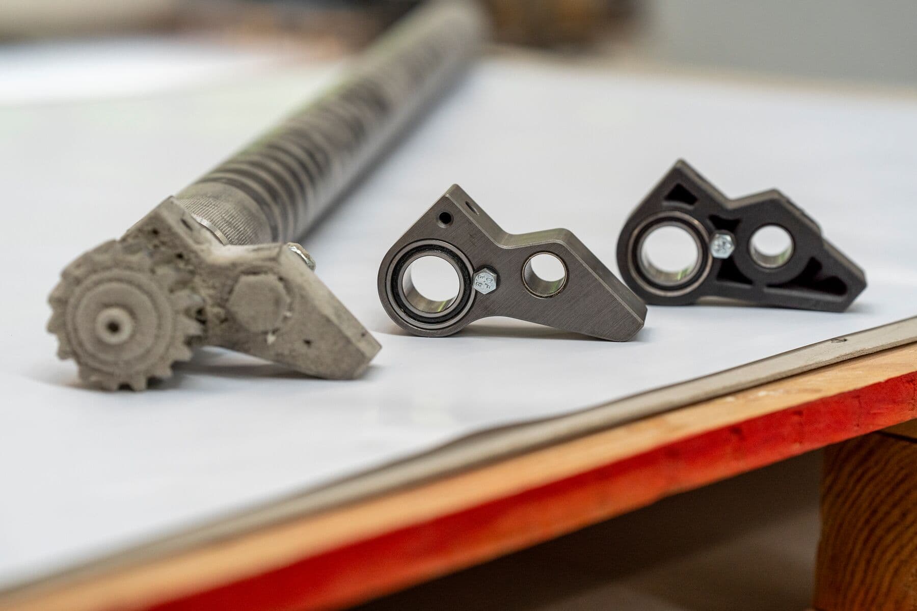
Spring Plunger
Company: Eaton
Here, large compression machines turn raw powder into a cylindrical MOV, then an extricator goes in, grabs the part, and pulls it back to a conveyor belt. The spring plunger presets the height of the extricator for different-sized MOVs. Previously machined nylon in a multi-part assembly with screws, they’re now SLS 3D printed in one piece, with their identifying symbols engraved into the file. The new parts make it easier and faster for operators to change programs.
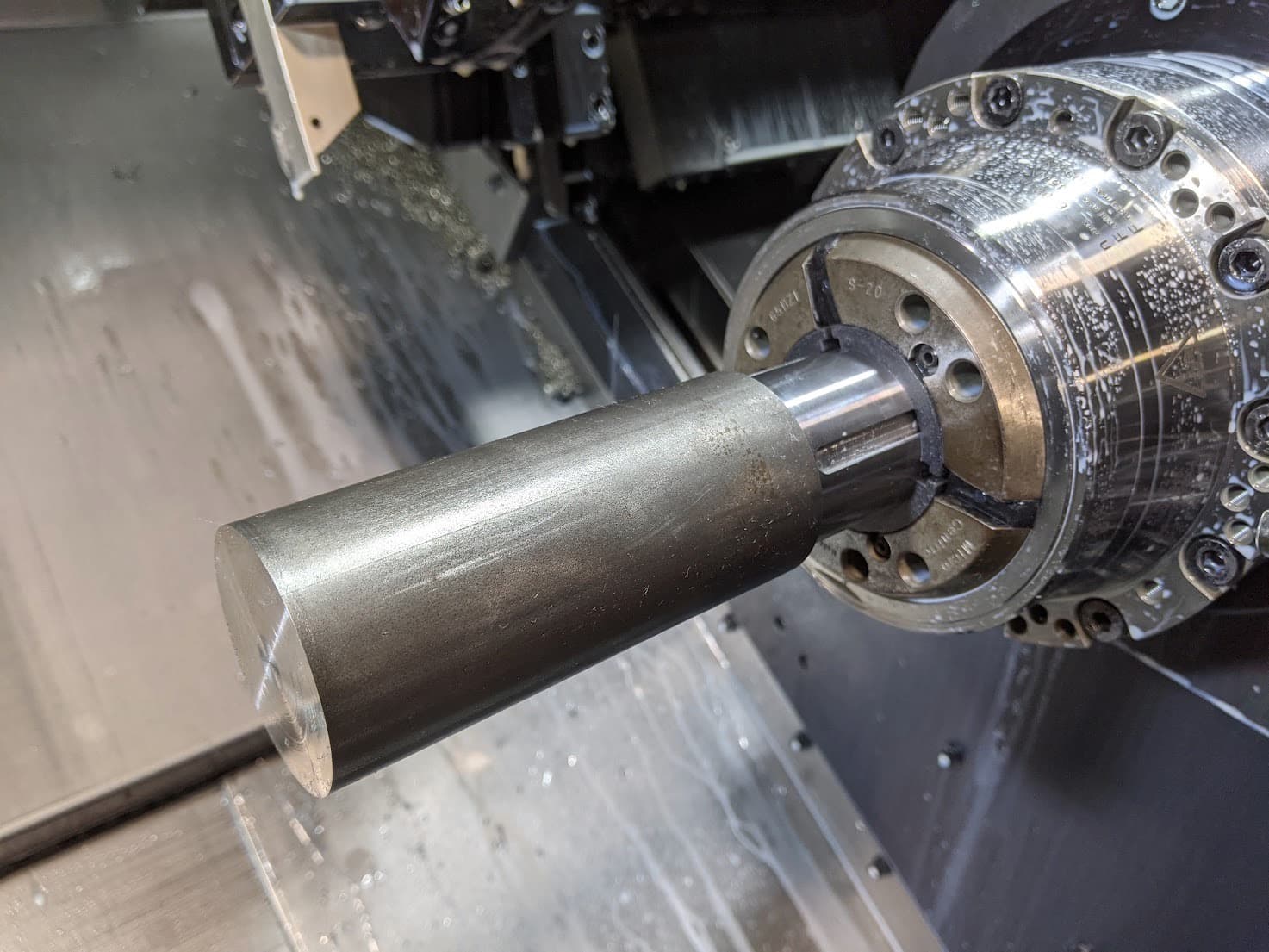
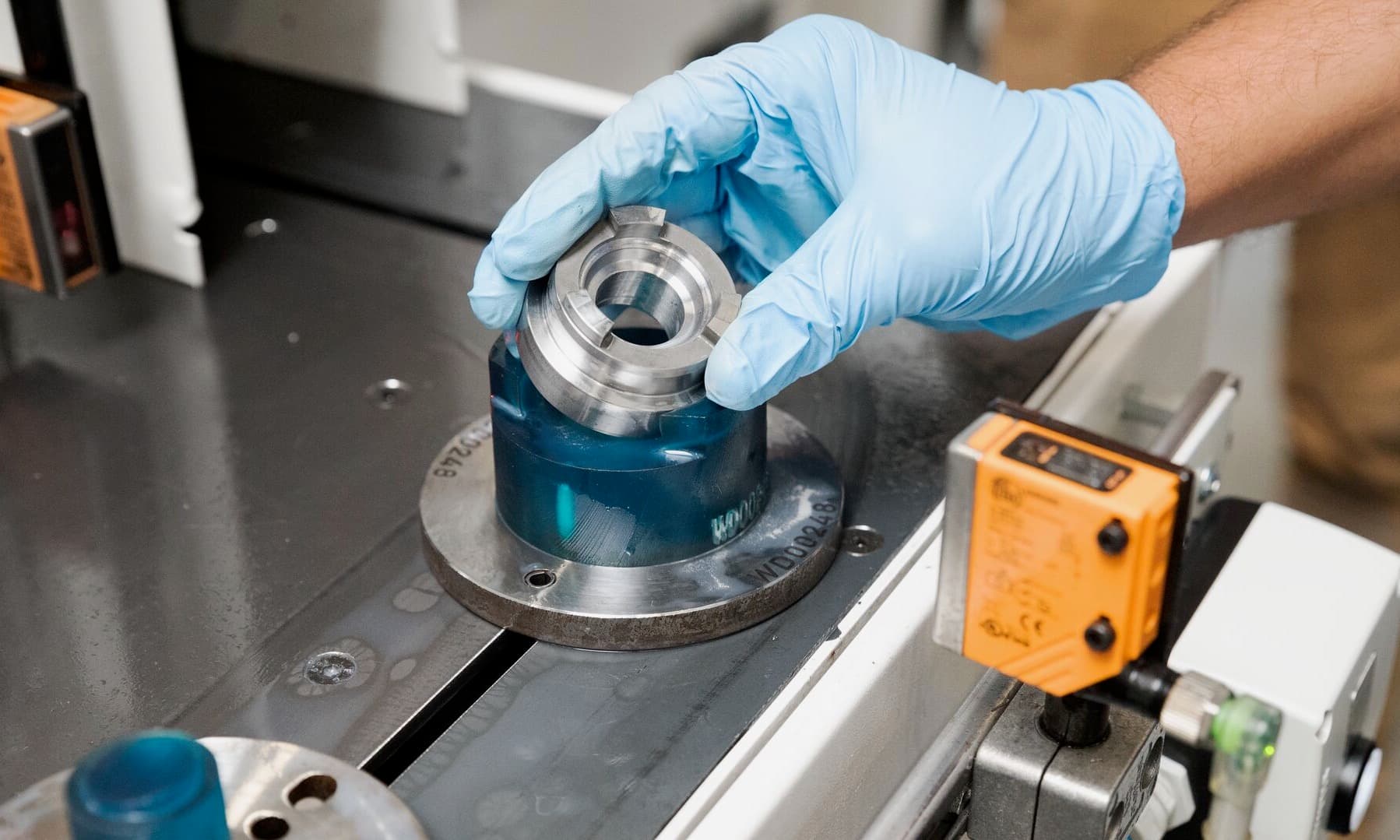
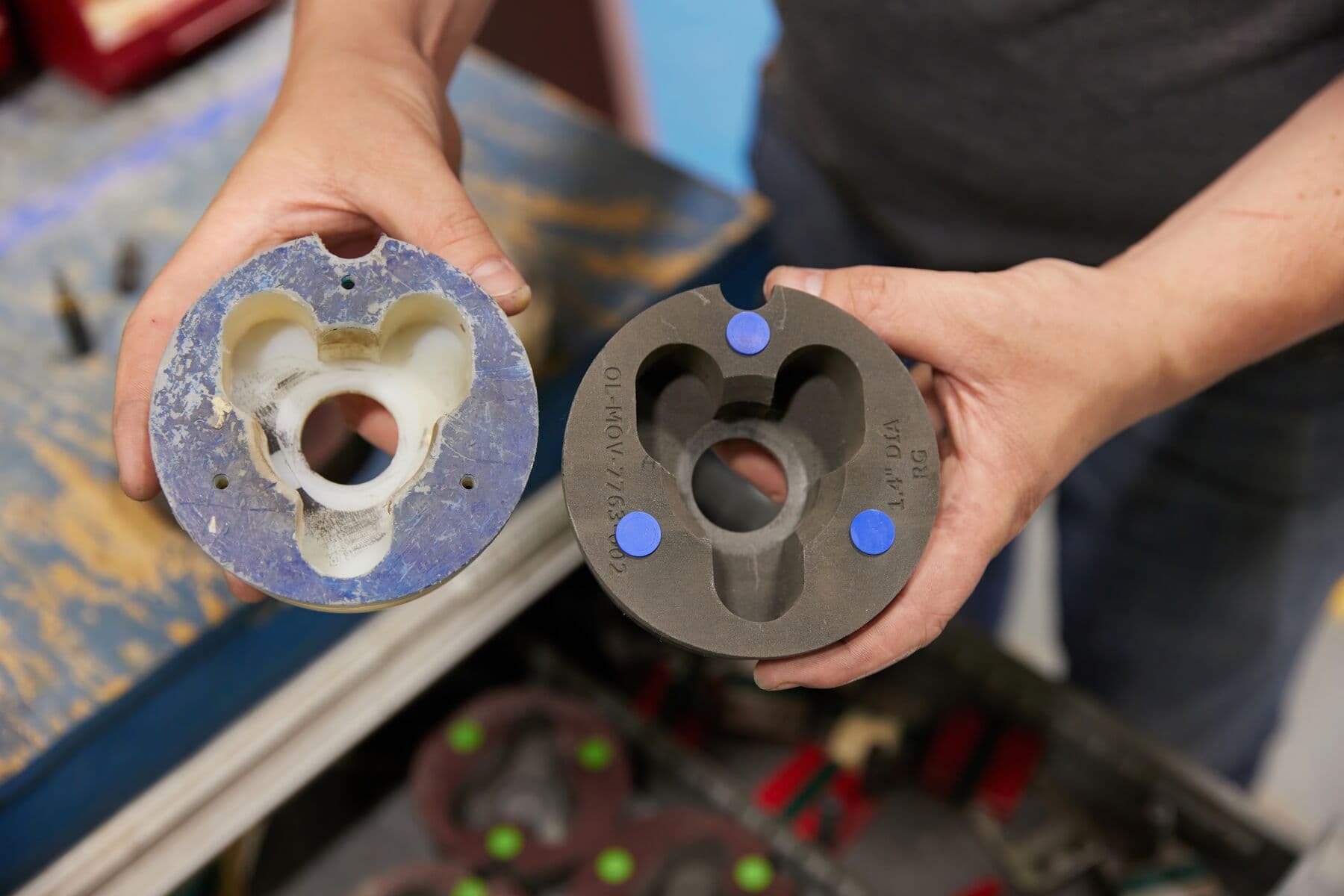
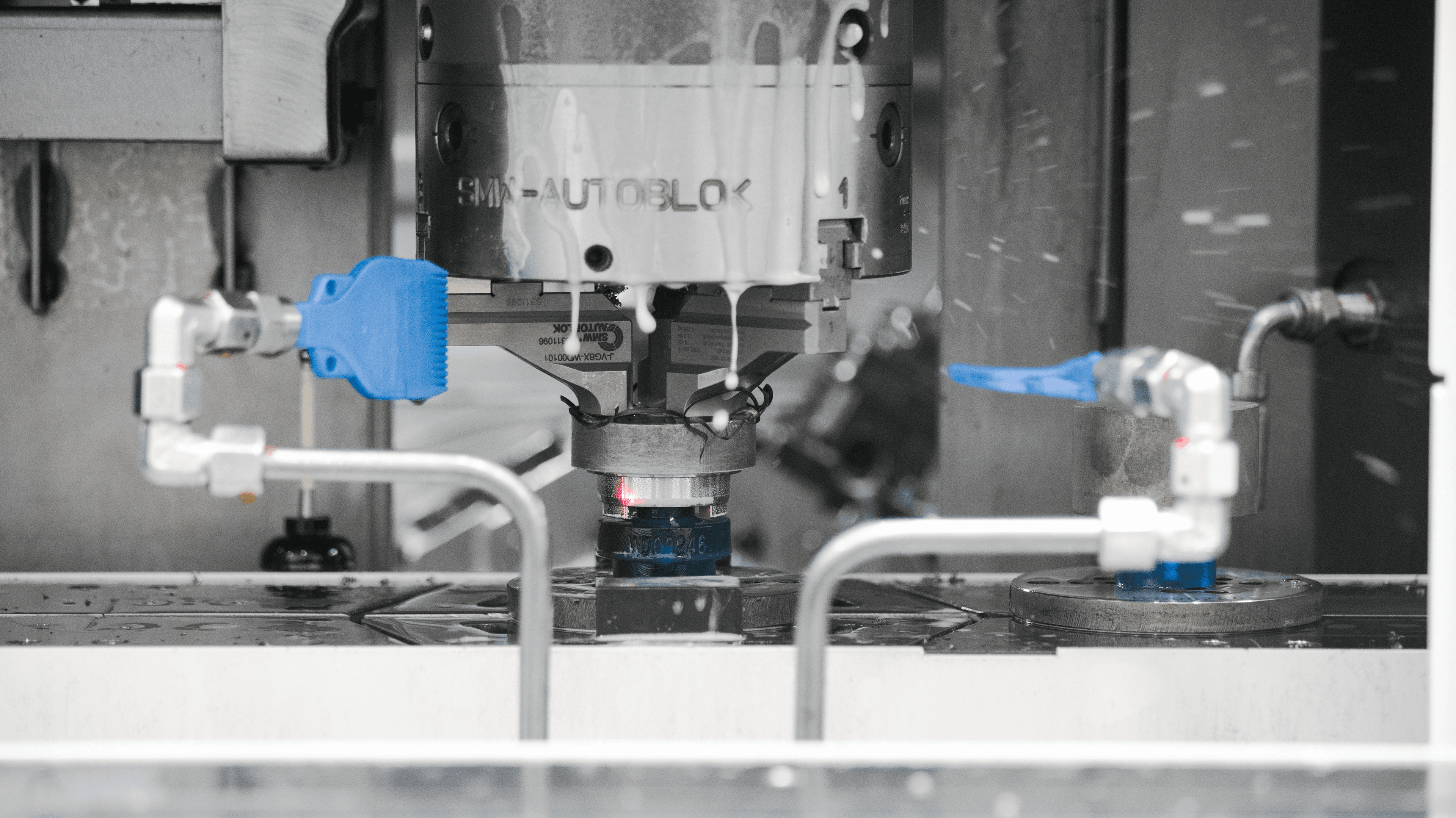
Custom Collet Pads
Company: The Factory Amsterdam (TFA)
TFA regularly fulfills production orders for machined metal parts in quantities between 1,000 and 10,000 units. Their CNC turning machine has to be adjusted for each new type of product. Instead of purchasing the customized collet pads needed to adjust the CNC turning machine, they SLS 3D print them. While purchasing the pads typically costs a few hundred dollars, on the Fuse Series, TFA can 3D print as many sets as they need, on-demand, for just $7 each.
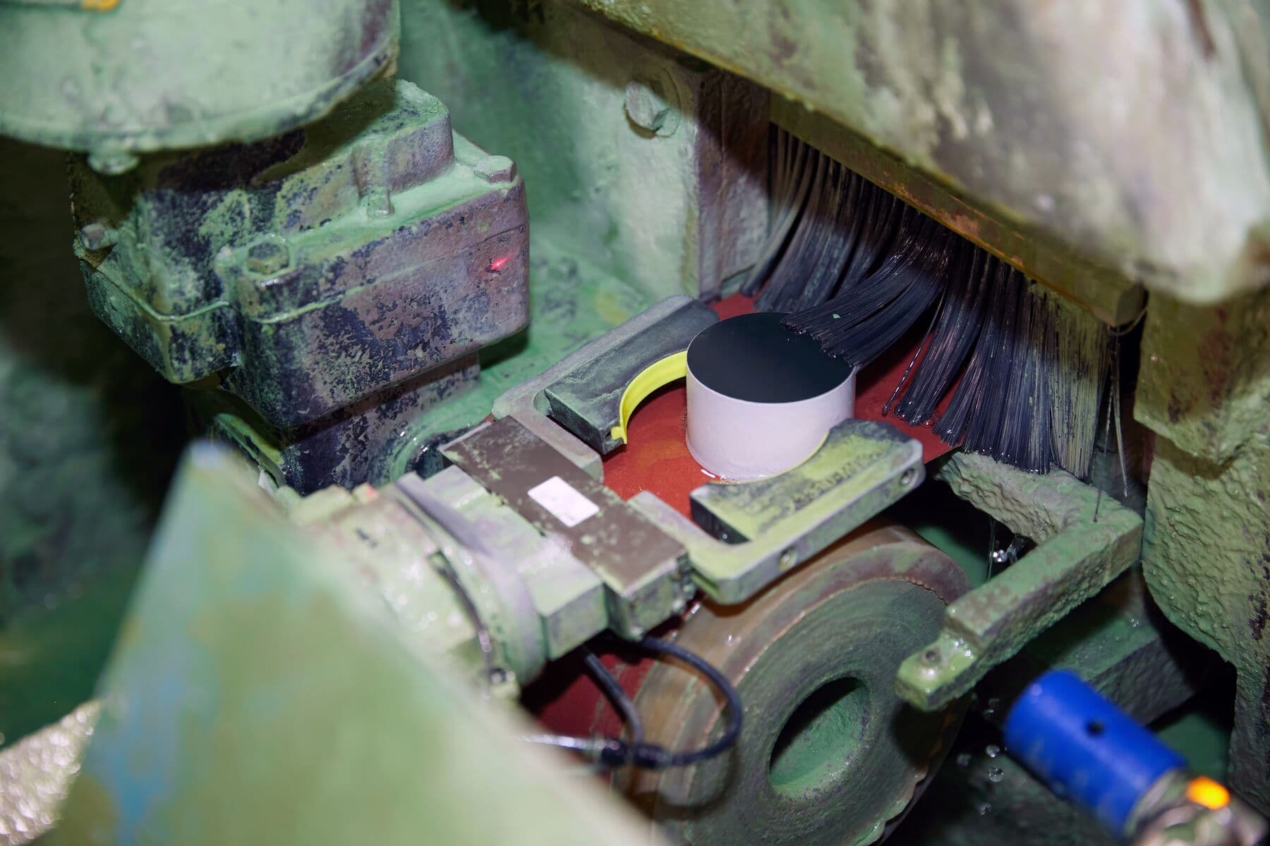
Replacement Impeller
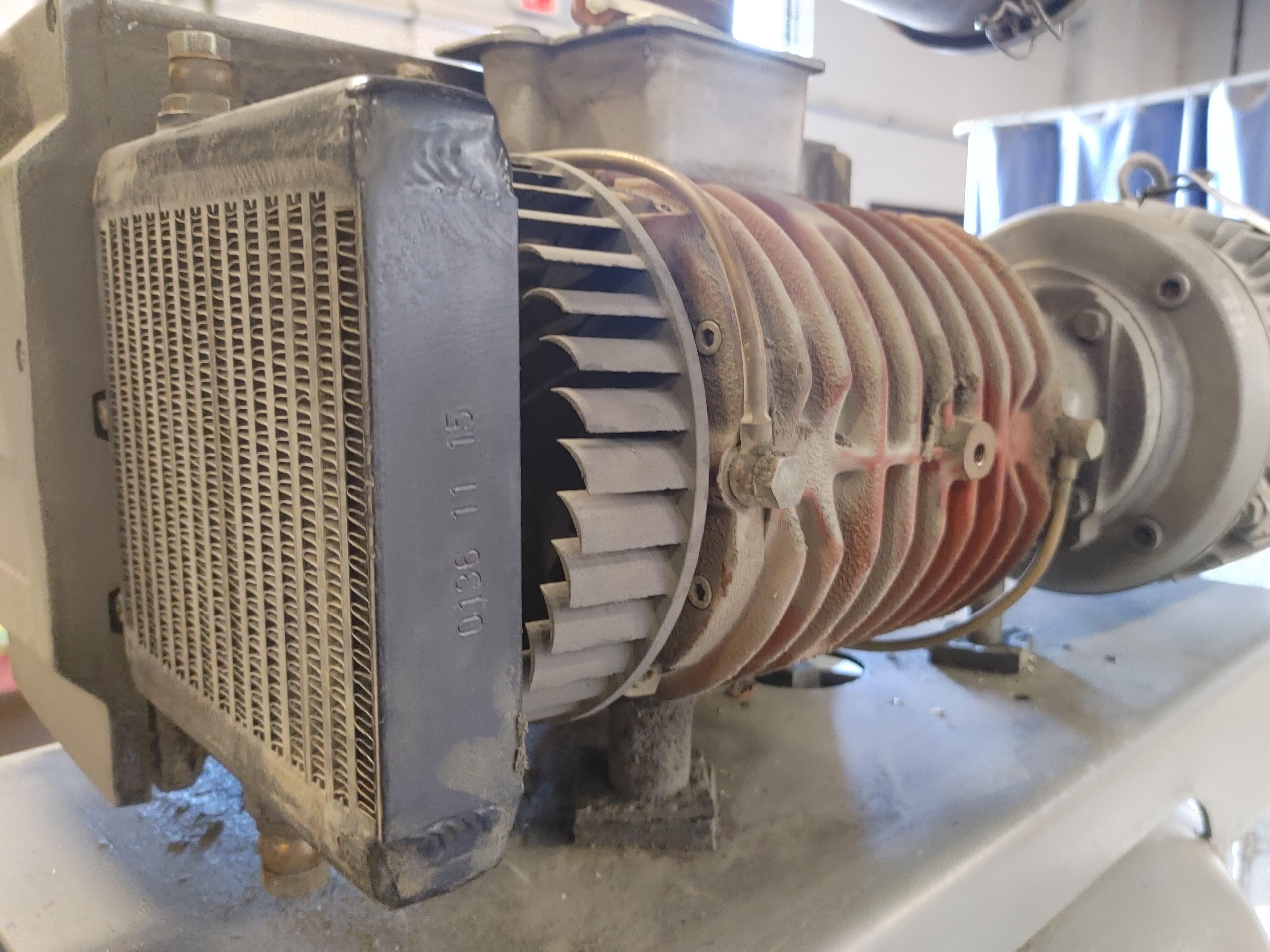
Company: Productive Plastics
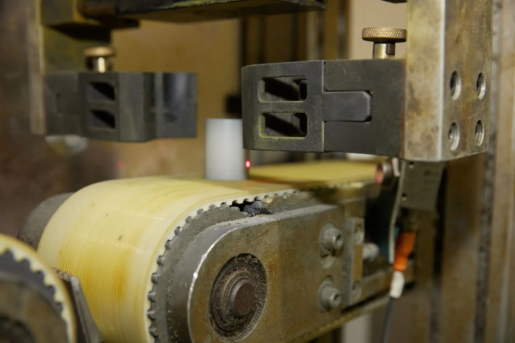
When the impeller on a thermoformer broke, this replacement was SLS 3D printed overnight on the Fuse Series in Nylon 12 Powder and worked immediately, getting the thermoformer back up and running. For six weeks, the replacement part functioned perfectly until an OEM replacement part arrived. The on-demand replacement part helped the company avoid a loss of around $30,000 due to machine downtime.
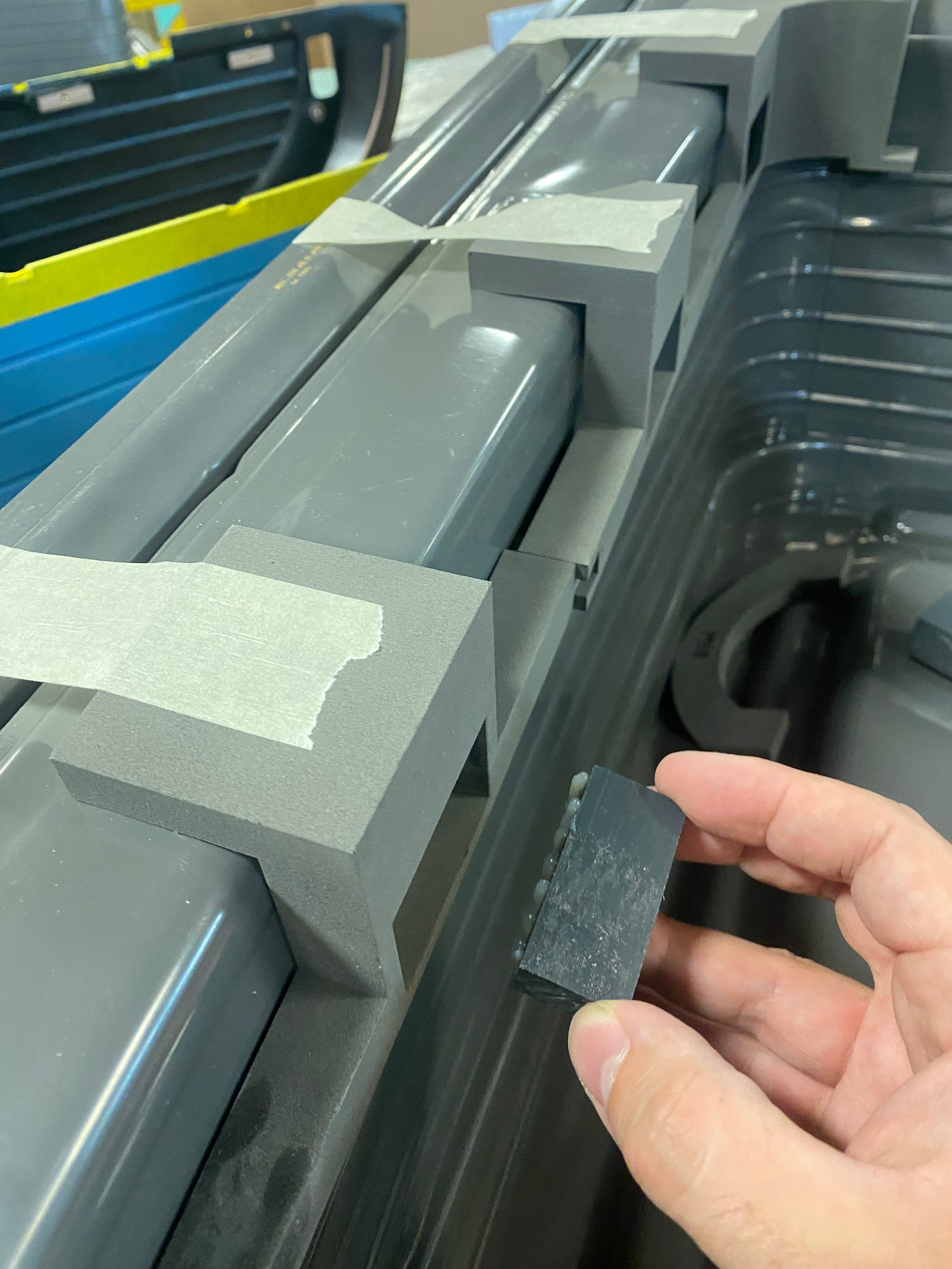
Custom Clamping Fixtures
Company: Productive Plastics
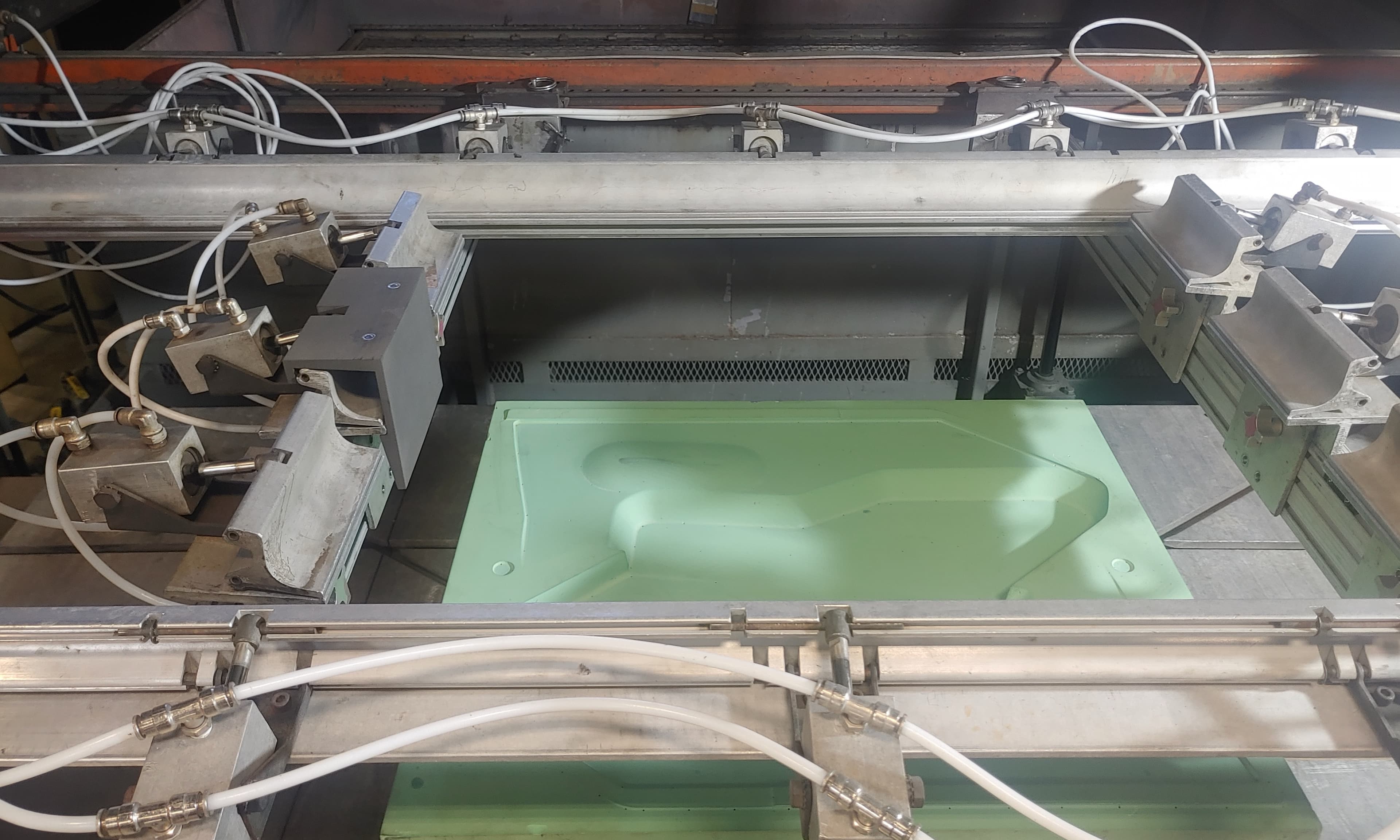
Productive Plastics also SLS 3D prints these custom clamping fixtures (grey part, middle left) for their thermoformers. Customizing the machines with these clamps optimizes their material usage - they can use smaller sheets and avoid waste. The 3D printed clamping fixtures went through 200 cycles at 200°F (93 °C), and the team estimates it could do thousands more. Despite the 3D printed tool being in direct contact with both the sheet and the mold, they did not observe any mark of heat deterioration on it.
Robotic Grippers
Company: AMRC
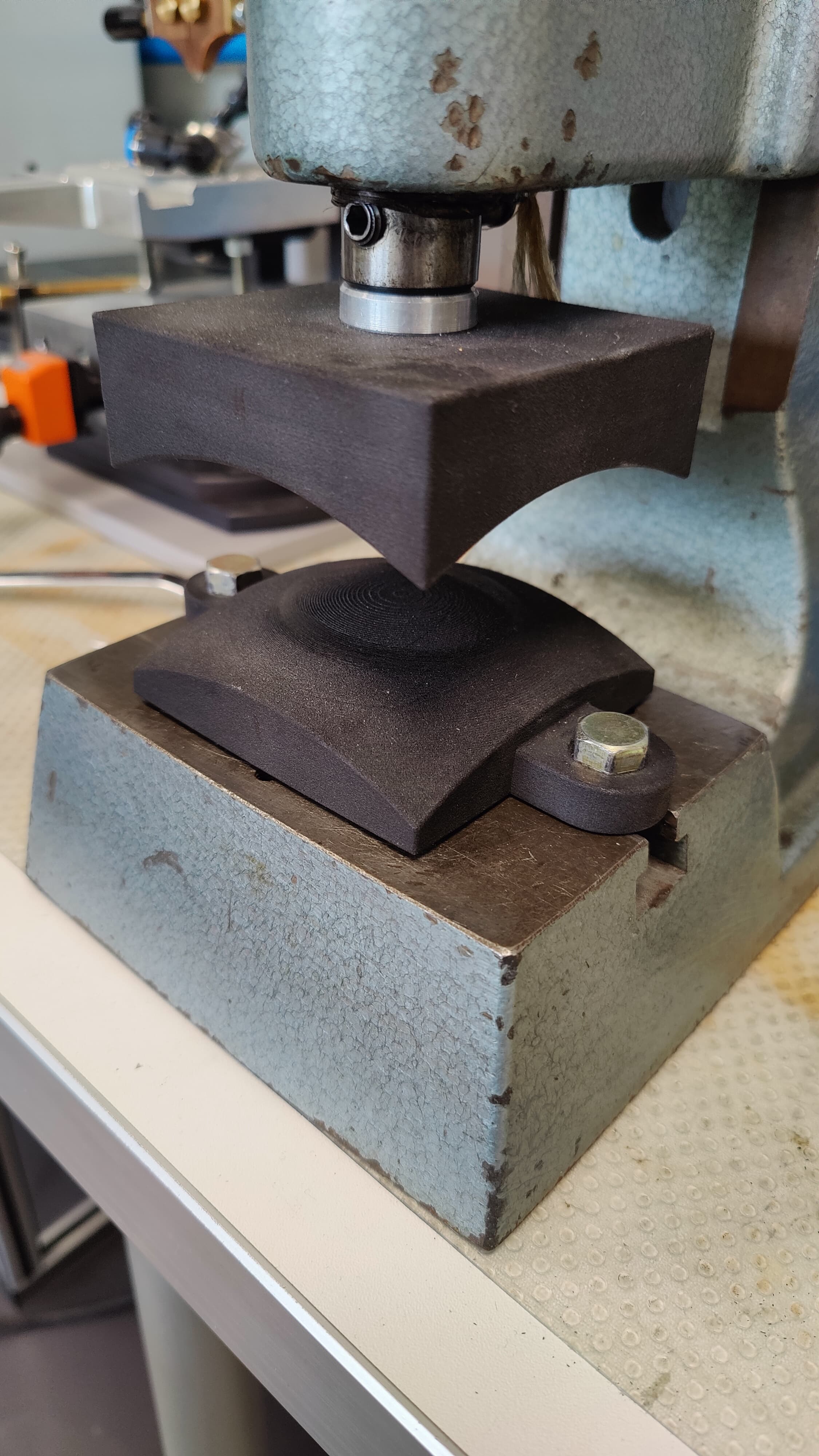
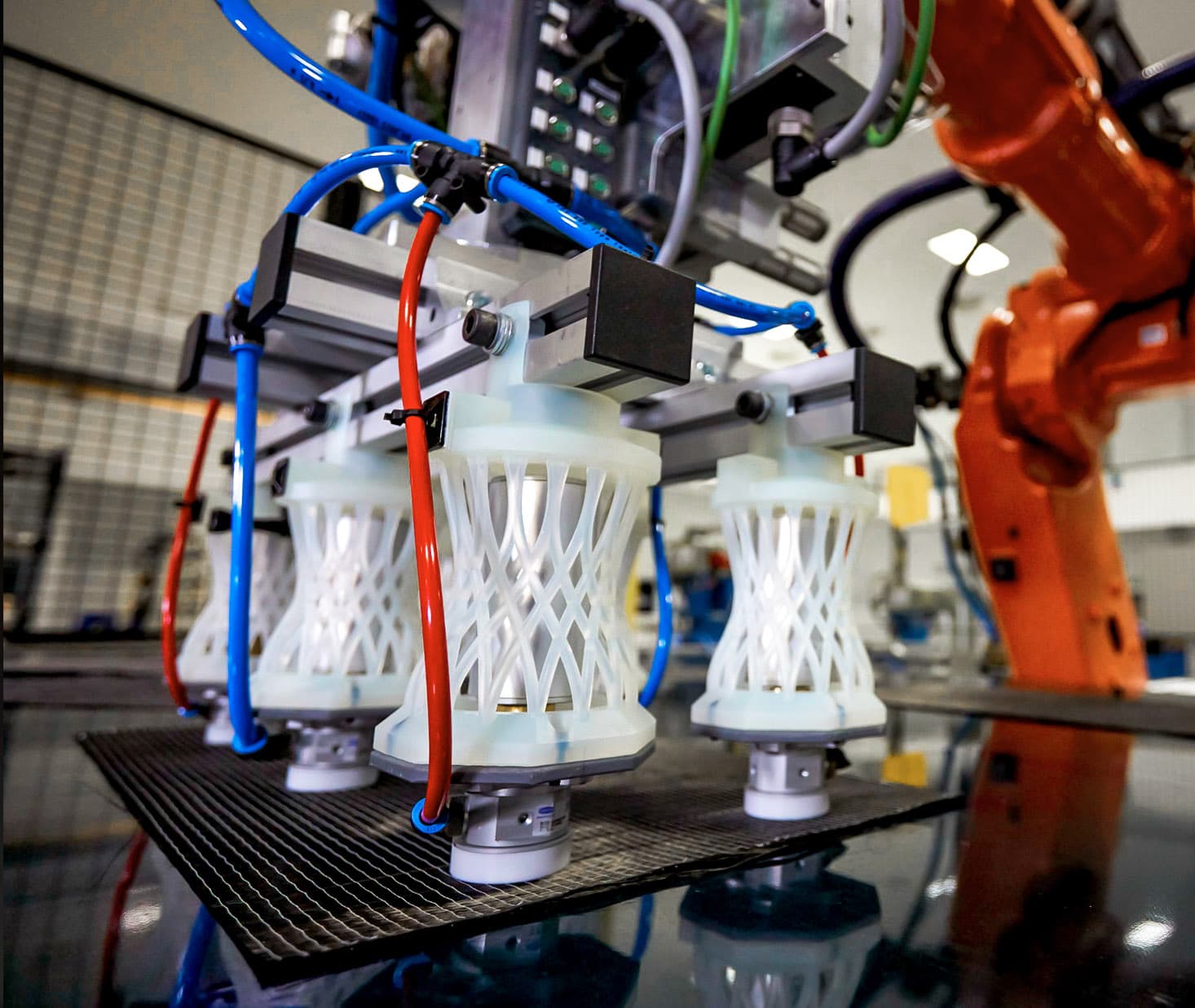
At AMRC, a leading manufacturing research institution, these robot gripper brackets were produced on Form Series SLA 3D printers. Composites researchers developed and printed highly intricate brackets to replace a robot’s worn-out compressed air grippers. The latticed design and pliable SLA resin give the right amount of springiness to accurately pick and place carbon fiber plies.
Lathe Jigs
Company: Pankl Racing Systems
Pankl manufactures motorcycle gearbox assemblies through multiple stages of steel machining using automatic lathes. Each stage of turning in the automatic lathes requires custom jigs. They were looking at a six-week lead time to outsource the jigs. By 3D printing them in-house with the Formlabs SLA printers, they decreased lead time by 90 percent and costs by 90%, leading to €150,000 in savings.
Product Movers
Company: Eaton
Eaton's centering devices move product between fabrication stations. They are made up of a main base that stays the same, with interchangeable SLS 3D printed top parts that have been redesigned and optimized for material usage, strength, and printing efficiency. Previously machined from aluminum and Delrin, the new parts are much cheaper, easier to switch out, and can be made on-demand.
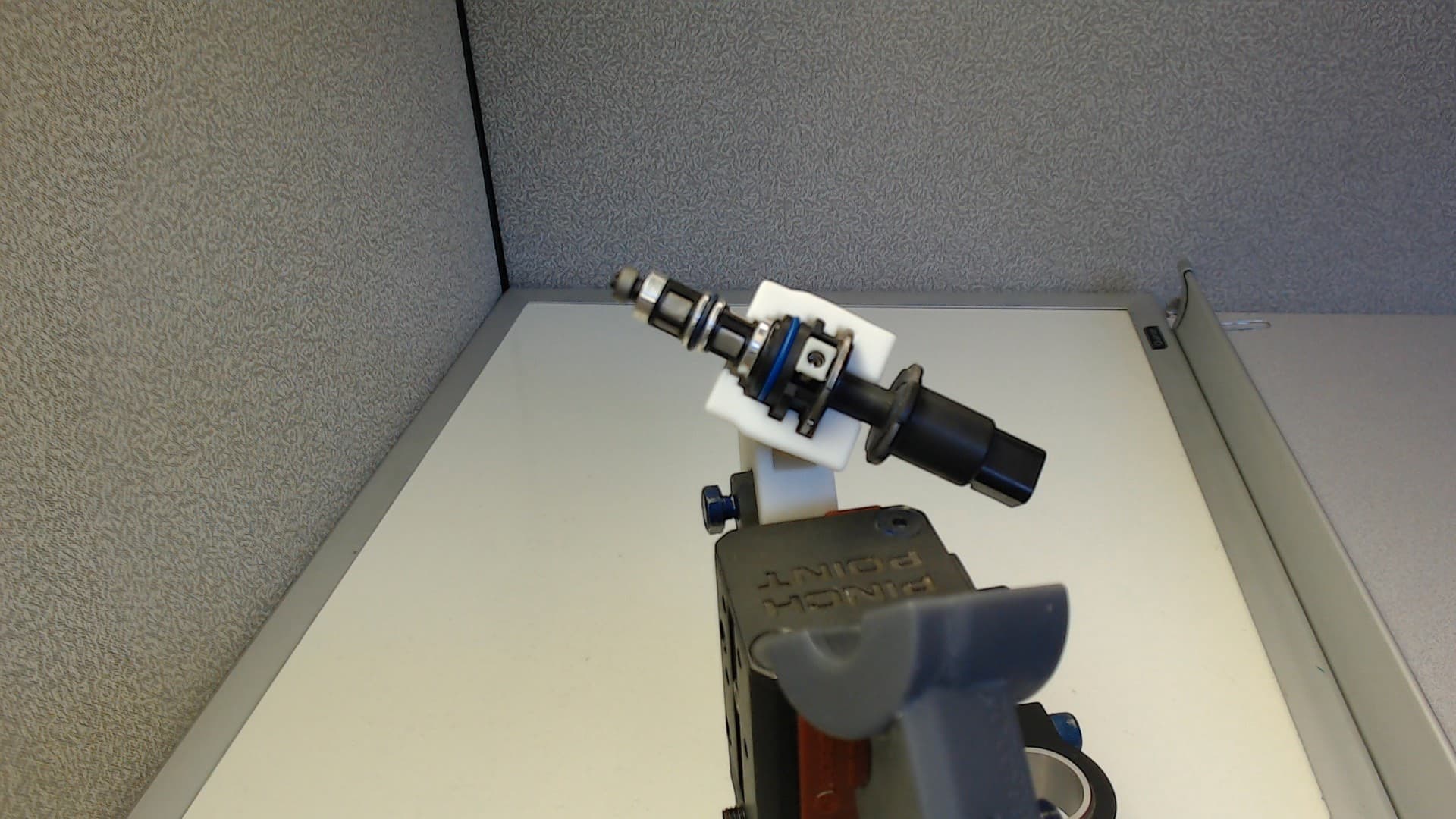
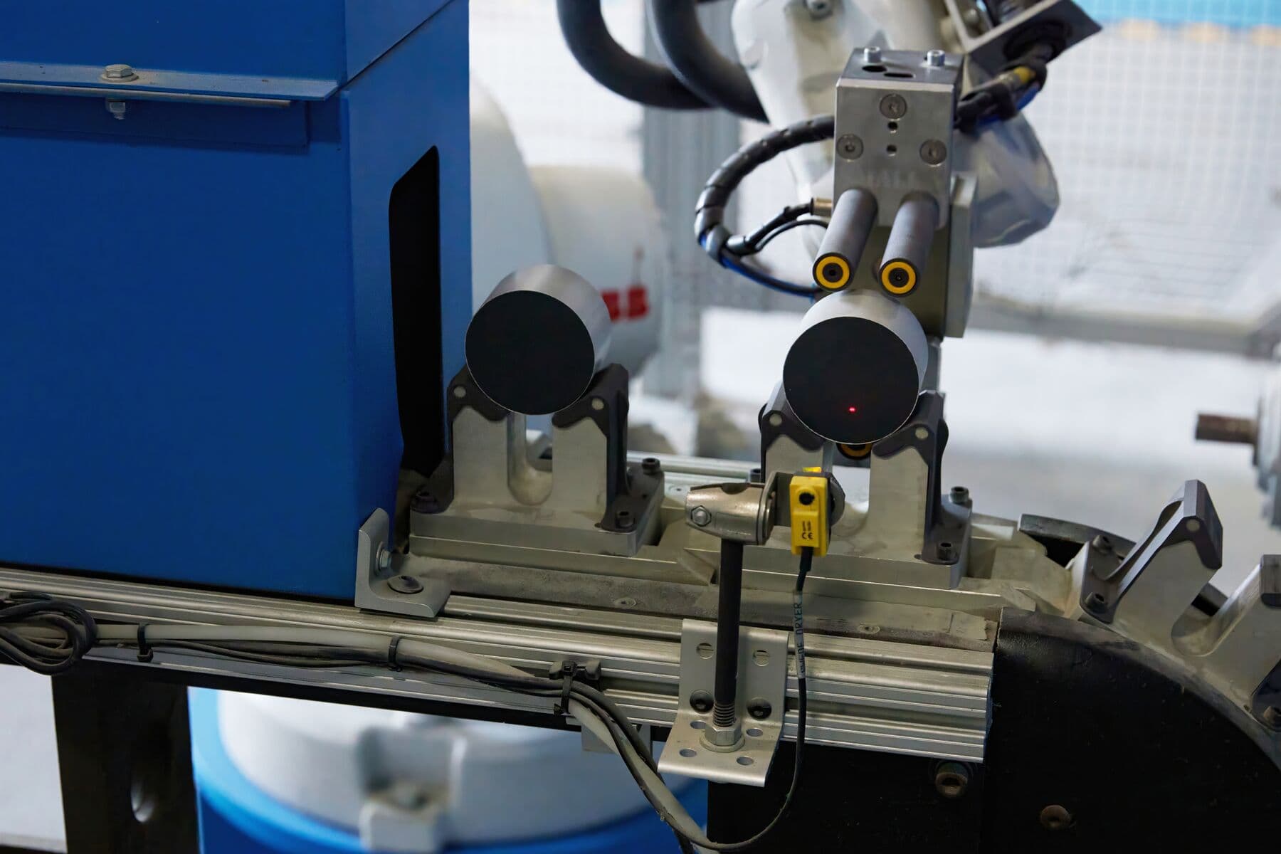
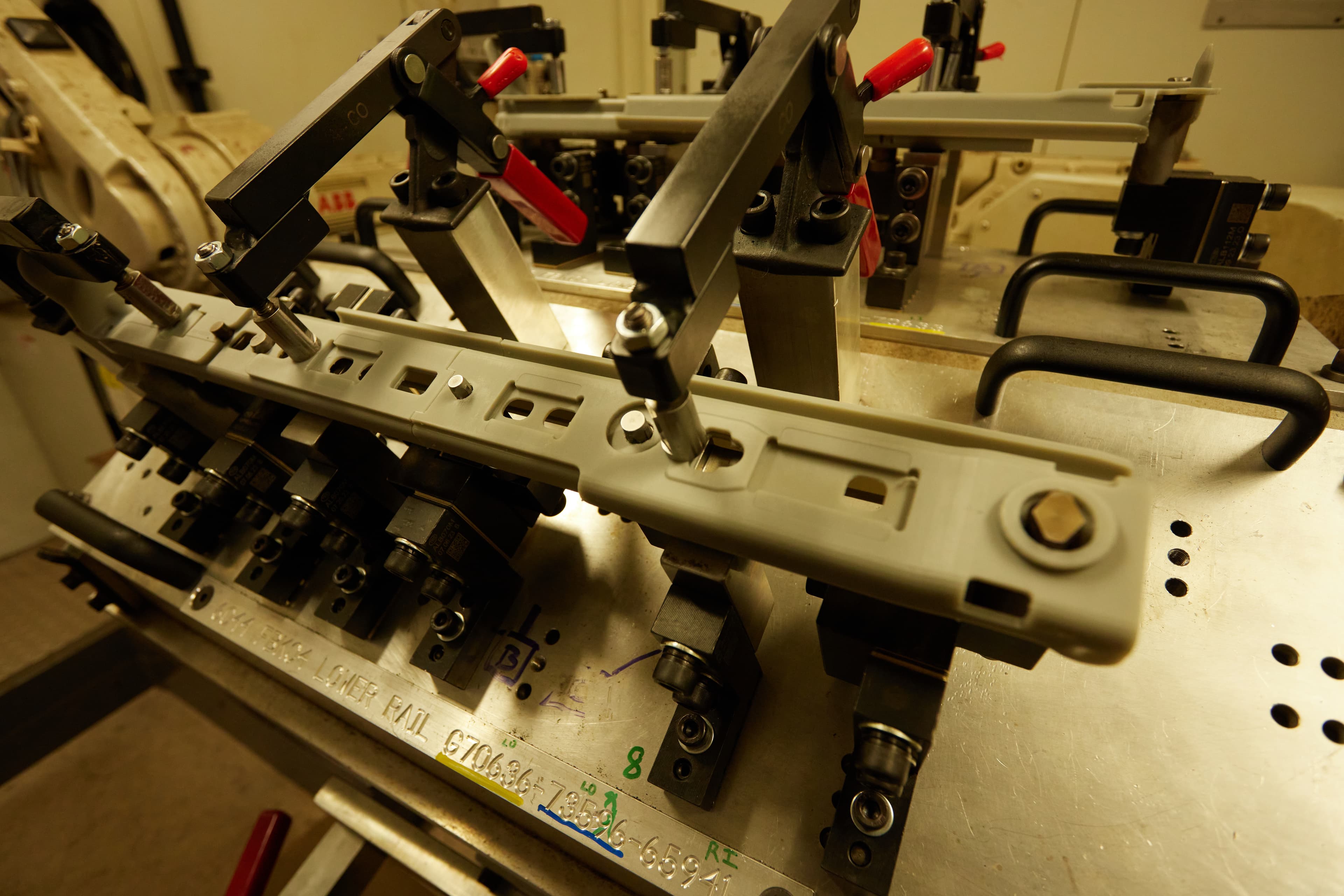
Fuel Injector Grippers
Company: STS Technical Group
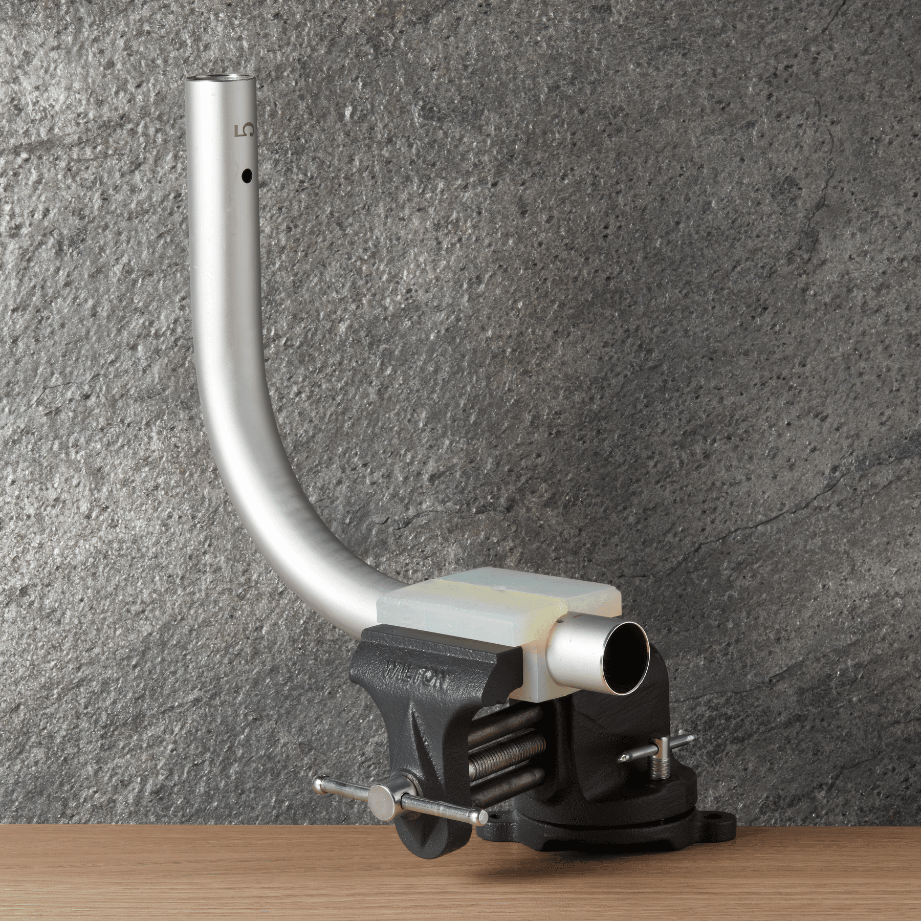
Engineering service provider STS Technical Group replaces generic robot grippers with 3D printed grippers for moving and positioning fuel injectors in a manufacturing environment. By switching from steel machined grippers to 3D printed polymeric grippers, they reduced the risk of marring on softer parts’ surfaces. Moreover, moving from a generic V-shape to a geometry that fits the fuel injector has improved the grip contact for better accuracy and reliability and reduced the pressure required in the process.
Assembly
Assembly is the manufacturing process in which individual components are put together to form a final product. On an assembly line, the parts are combined in sequence to a semi-finished product, moving from workstation to workstation. Lines are either automated, manual, or a combination of both. They are set on the factory floor and involve many steps, significant equipment, and labor. Optimizing assembly lines for efficiency is critical to decrease cycle times and, therefore, the costs of production. 3D printing assembly tools can foster continuous improvement in-house, also referred to as Kaizen, to optimize the factory floor and increase operational agility:
- For many products, assembly is the most labor-intensive step of production. Replacing bulky metal tools with 3D printed, lightweight, ergonomic, and precise assembly jigs increases operator safety and workflow efficiency.
- 3D printing allows manufacturers to create complex, part-specific tools that match the multiplicities of SKUs. It makes it possible to move from a physical to a digital inventory and provide a tailored solution for each unique product.
Assembly Guides
Company: Productive Plastics
During assembly of thermoformed parts, Productive Plastics used to either forgo guides altogether and eyeball the measurement or use wooden blocks that had been glued together and then machined to the right dimensions. Both methods were laborious, slow, and created mistakes that needed to be undone. Now they 3D printed custom locating jigs on the Fuse Series in Nylon 12 Powder. These help quickly fix the blocks at the right place. These tools ensure the part is accurately installed and the operation is repeatable throughout the assembly runs.
Assembly Jig
Company: Eaton
This SLS 3D printed assembly jig holds an underoil lighting arrestor in place to be placed into stacks that will eventually become the surge arrestors. Previously, the jig was a multi-piece assembly machined Delrin and aluminum, expensive and difficult to get quickly if it wore out. Now, operators can request a replacement printed on the Fuse Series and have it the next day.
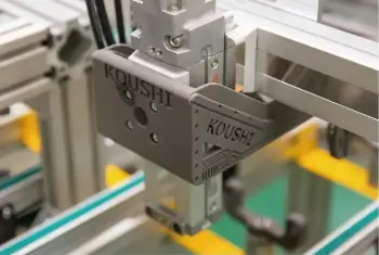
EOAT
Company: Koushi Kagaku Kogyo
Koushi Kagaku Kogyo's automated assembly machines use many parts printed with Fuse 1, including lifts and grippers. High-strength Nylon 12 Powder parts can easily be bolted or machined, so that the SLS 3D printed parts can be attached easily to all different parts of the assembly system.

EOAT
Company: Eaton
This robotic end-of-arm-tooling (EOAT) picks up the MOVs from one conveyor belt and moves them to another as they enter the metallizing station. The EOAT can wear out, and reprinting in bulk on the Fuse Series is the easiest and least expensive replacement method.
Scratch Guards
Company: Deutsche Bahn
During the disassembly, restoration, and reassembly of train car luggage racks at Deutsche Bahn, the train car walls can often get scratched by the edges of the racks. These SLS 3D printed scratch guards are somewhat pliant and have a non-scratch surface, because they're printed in TPU 90A Powder; they protect the walls from scratches and are easy to get on and off the racks themselves.
Cable Guide
Company: Heidelberg
This flexible cable guide at Heidelberg is part of their customized robotic assembly. The cable guide is SLS 3D printed on the Fuse Series in TPU 90A Powder. It's complex, organic geometry offers a long-term, durable solution for protecting the cables from wear and tear.
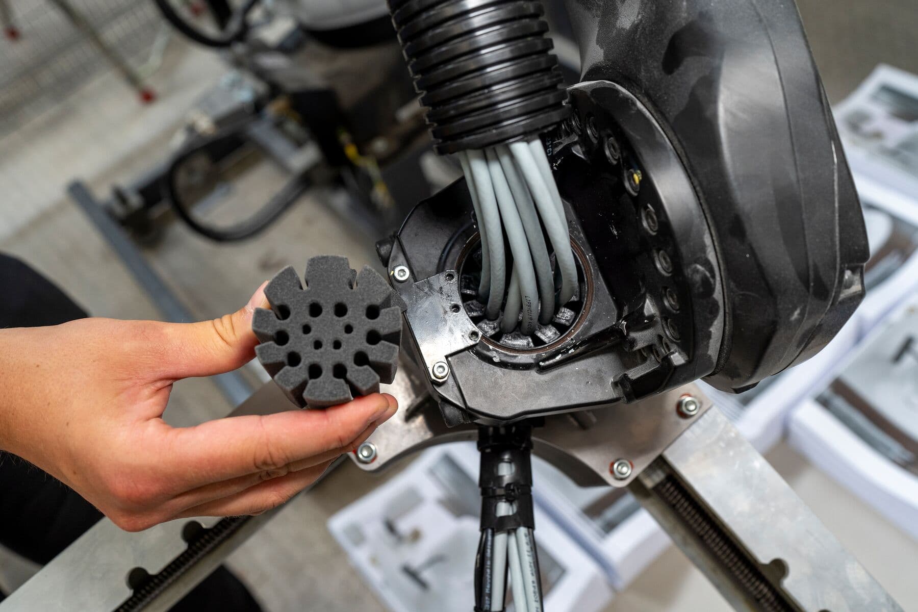
Replacement Joints
Company: Heidelberg
Elsewhere at Heidelberg, these SLS 3D printed replacement parts (in Nylon 12 Powder) are assembled with bearings and anti-friction metal components. The joints hold metal rollers that rotate at high speed and weigh up to 13 kg each. SLS 3D printed nylon can replace machined aluminum and steel in these applications.
Finishing
Finishing is a broad range of techniques performed after fabrication to add further properties to the finished product. They are employed to enhance appearance, modify chemical and electrical characteristics or hardness, build in or remove elements and flaws, and more. Typical finishing methods include blasting, coating, dyeing, painting, electroplating, or polishing.
3D printed finishing tools ensure the procedure is accurate and repeatable while reducing labor and risks of errors. In many finishing techniques, such as coating, dyeing, or painting, the operator wishes to protect some elements of the product from the treatment applied. This procedure is called masking. It is traditionally made with tape, plugs, coverings, masters, vinyl cutting, or machined parts. 3D printed masking devices can either support taping or simply replace it, with a range of sturdy and flexible materials that will preserve part integrity.
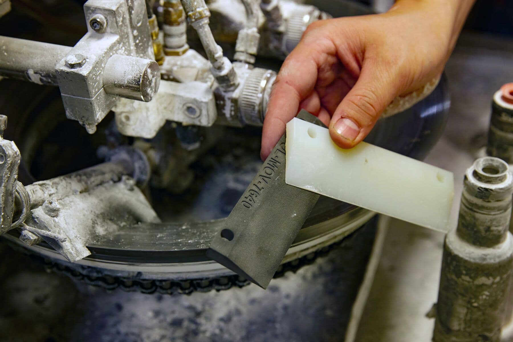
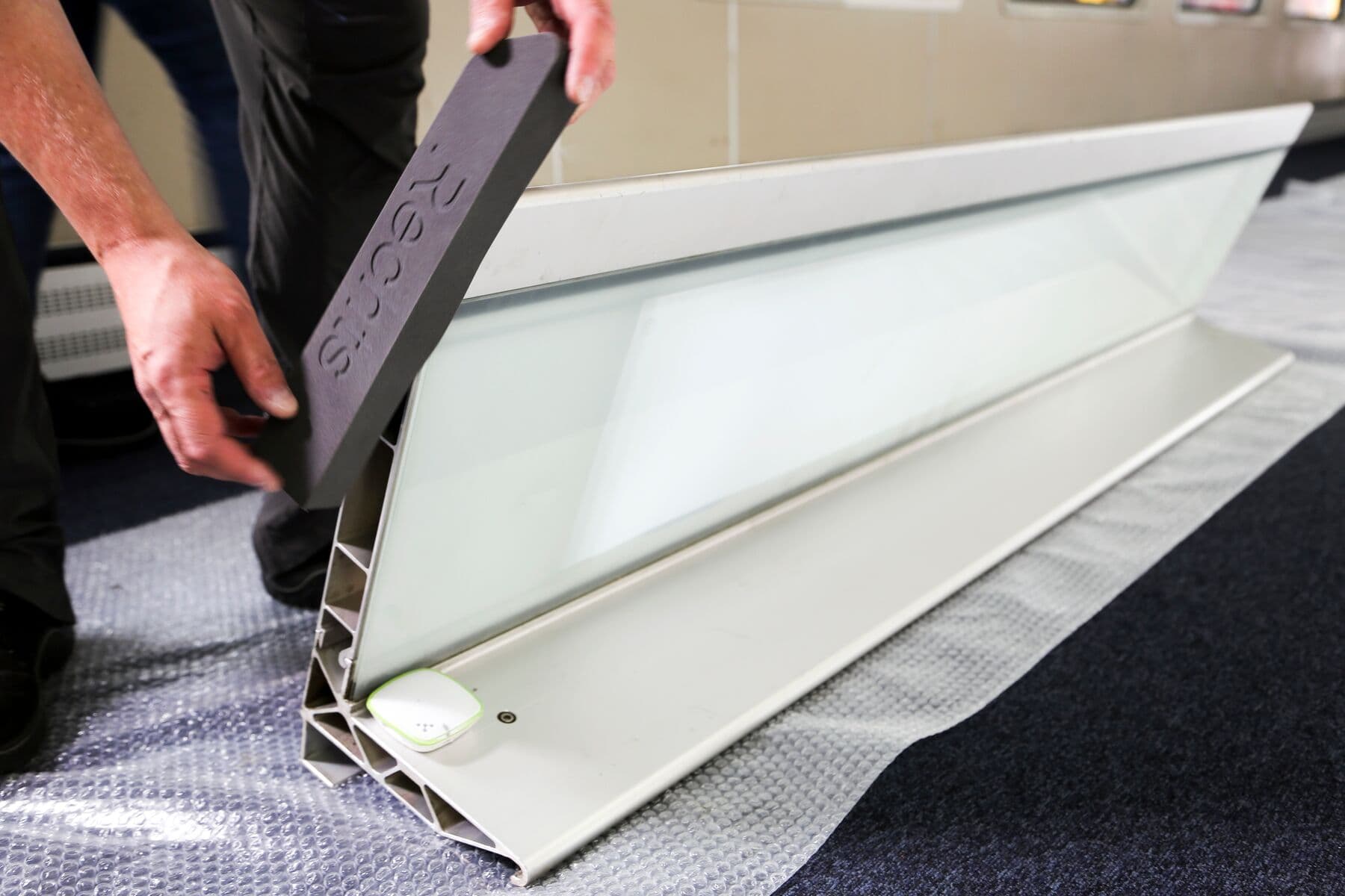
Mask Ring Scraper
Company: Eaton
During glass collaring, paint builds up on this metal ring (mask) and needs to be cleaned so it doesn’t deposit paint onto the parts. A ring scraper keeps paint from building up. Previously machined nylon (left) in a multi-part assembly with screws; they’re now SLS 3D printed in one piece, with their identifying symbols engraved into the file. The new parts make it easier and faster for operators to change programs.
Flipper Arm Gripper
Company: Eaton
The flipper arm picks up the larger, station-class MOVs and moves them through the grinding process, exposed to coolant chemicals the whole time. To increase grippiness, the SLS parts have an inset of FDM 3D printed TPU (neon yellow) on them, which is printed in long strips and cut down to size. They were previously machined from Delrin and wrapped with a rubber band for grippiness.
Masking Parts
Company: Productive Plastics
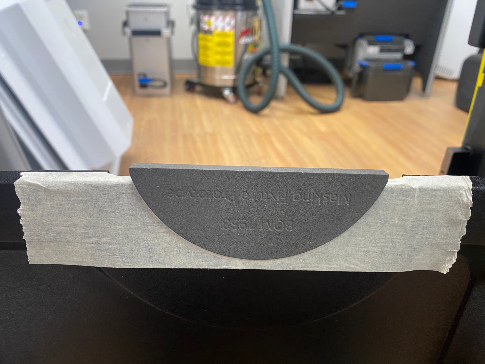
In one finishing step, Productive Plastics copper spray paints parts where conductive shielding application is critical. Technicians were previously taping over a critical copperized surface, then stenciling by hand where the copper ended. That cut was just being eyeballed, and mistakes and scratches to the copper were common. This 3D printed part acts as a stencil around which a technician will cut the rest of the tape away, ensuring that the copper-coated part remains free of paint, while the rest of the surface is painted black.
Masking Stencil
Company: Deutsche Bahn
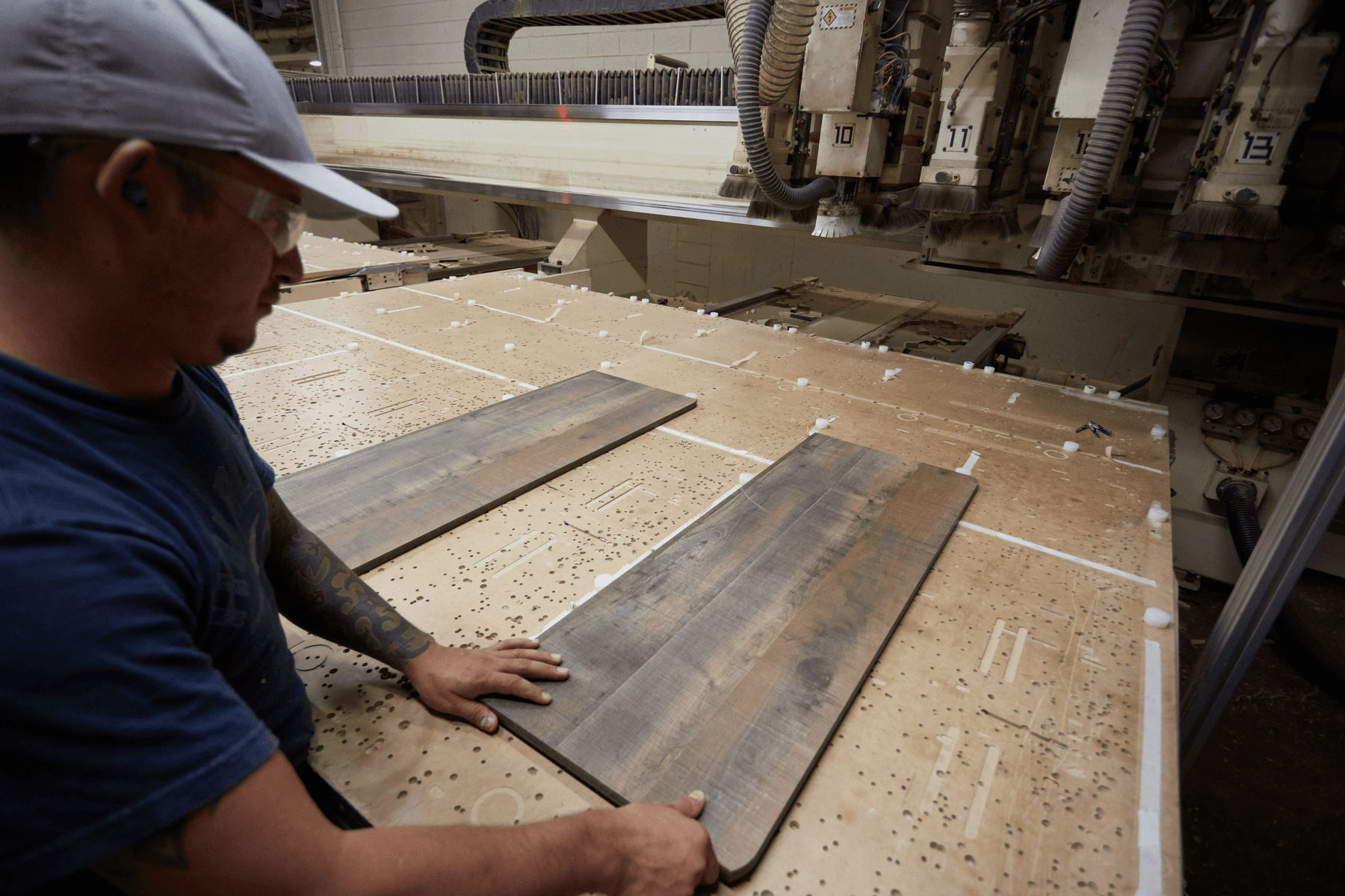
Deutsche Bahn, one of the largest railway companies in the world, reduces costs and optimizes MRO operations of their rail cars by using 3D printed manufacturing aids. During the restoration of ICE1 coaches, all plastic components are removed, sanded, filled, and repainted. With an SLS 3D printed stencil, they can reduce 30 minutes of painting to just two minutes.
Inspection
Inspection is a critical aspect of the Quality Control (QC) process and is the last manufacturing stage before shipping. It is a set of procedures that ensures the product meets the specified requirements. They involve examination, measurement, or testing. Common inspection methods include dimensional analysis, where the final product is checked against its allowed tolerances. It is performed with measuring gauges or checking fixtures that range from a simple piece of material that can be directly 3D printed, to complex machinery such as a coordinate measuring machine (CMM) requiring workholding devices.
Manufacturers can leverage the design freedom of 3D printing to generate custom checking fixtures and gauges in-house tailored to their parts and QC procedure. Complex and accurate inspection tools can be built on demand to accelerate production while ensuring the product meets customer expectations.
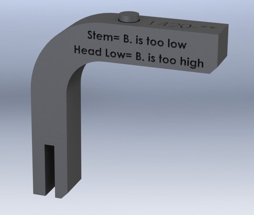
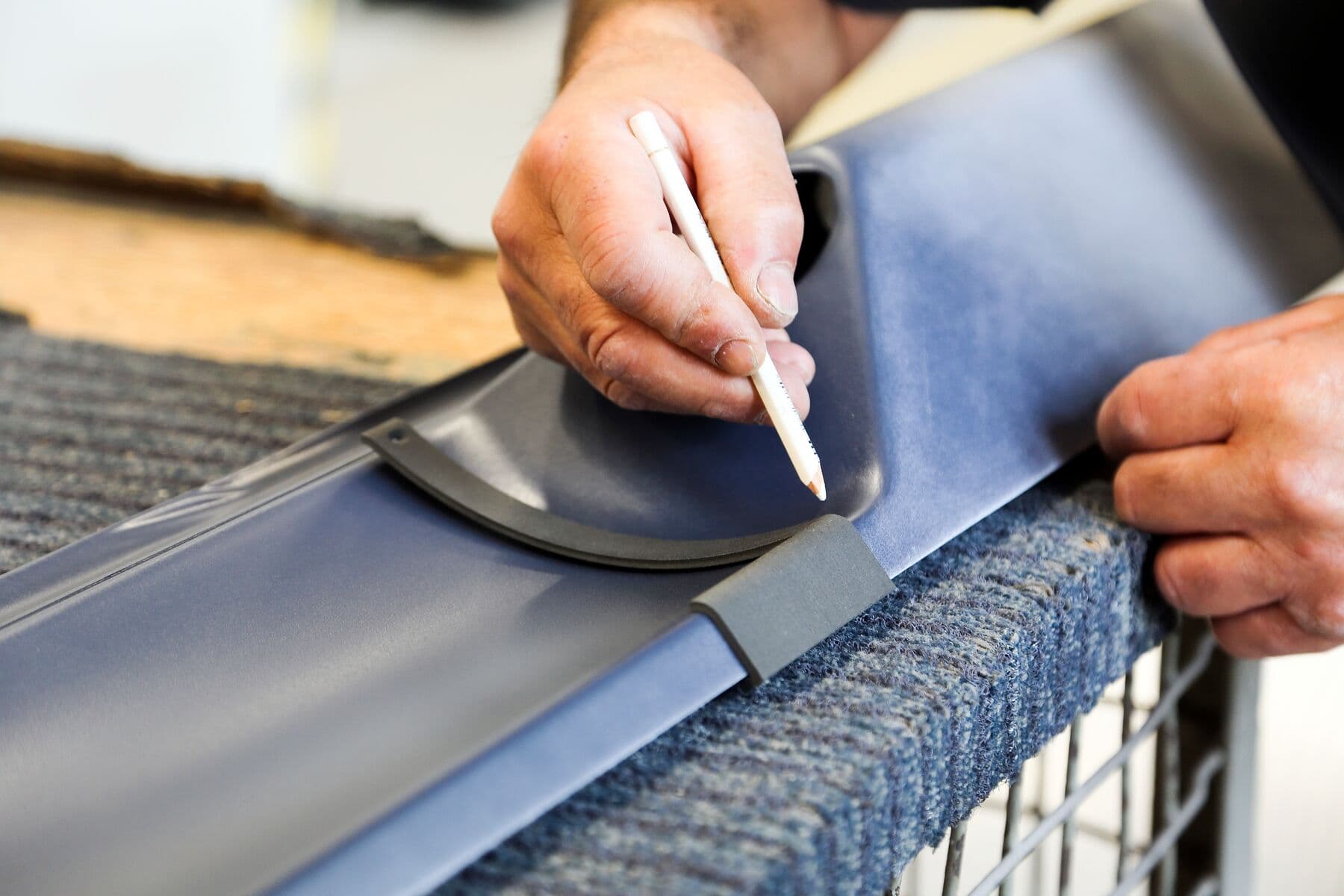
Height Check Fixture
Company: Productive Plastics
This particular checking fixture from Productive Plastics is used to measure the dimensions of a metal bracket. The team 3D printed the tool in Nylon 12 with the Fuse 1, as one piece. The bottom of the part sits within the corner of the bracket while an action insert moves up and down to indicate if the part is valid or out of specs. They incorporated inscriptions into the design so that the operator can easily read if the actuated insert is too low or too high.
Testing Bench
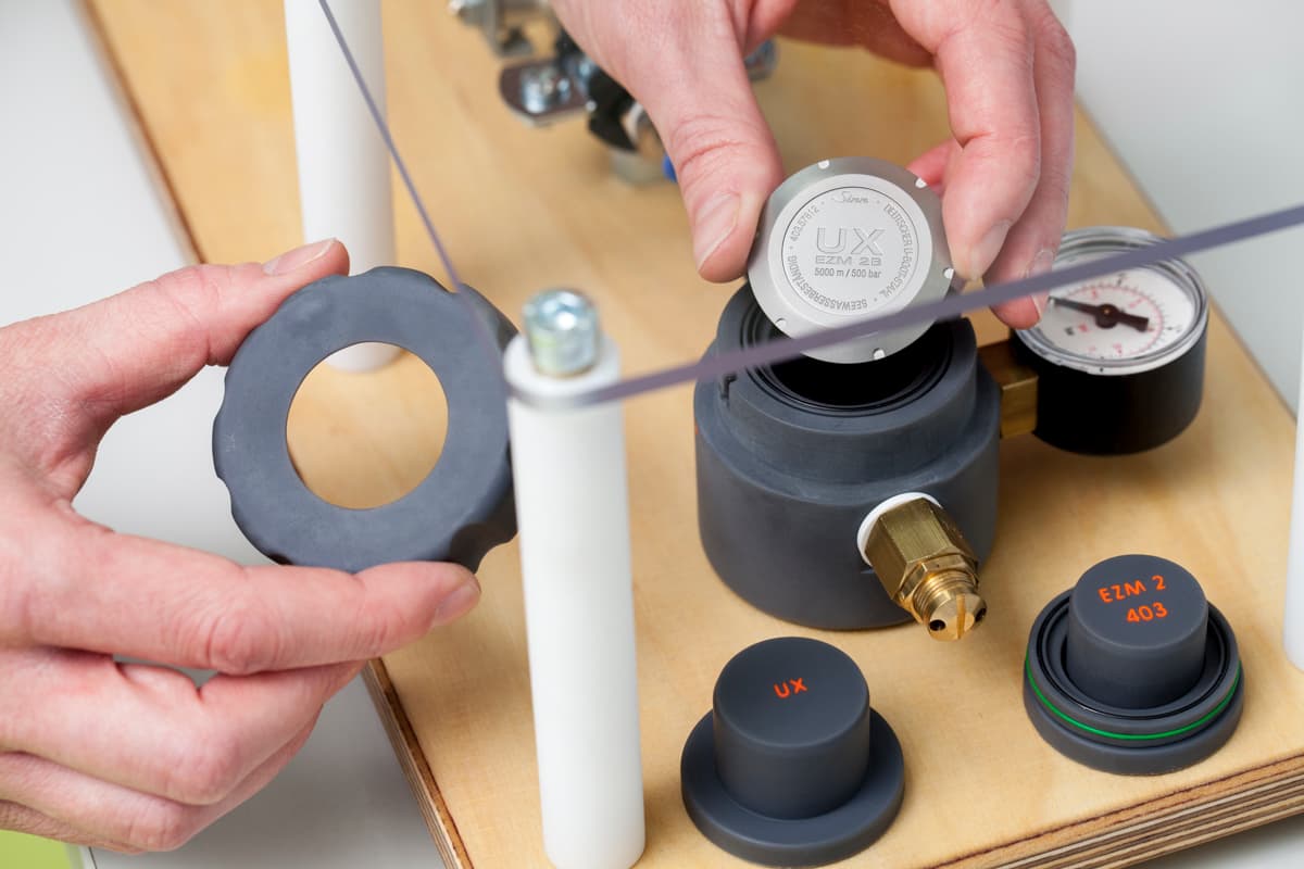
Company: Sinn Spezialuhren
Watch manufacturer Sinn Spezialuhren 3D printed custom brackets for their testing system, with Tough 2000 Resin on a Formlabs SLA printer. These brackets ensure a tight, secure fit is made for the watchpiece while it's being inspected and tested for functionality.
AI Camera Enclosure
Company: Eaton
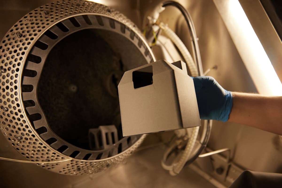
This camera cover was developed by Eaton Olean specifically to protect the expensive and delicate AI cameras from too much environmental light, so they can focus more easily on the MOVs in front of them as they’re being checked for quality.

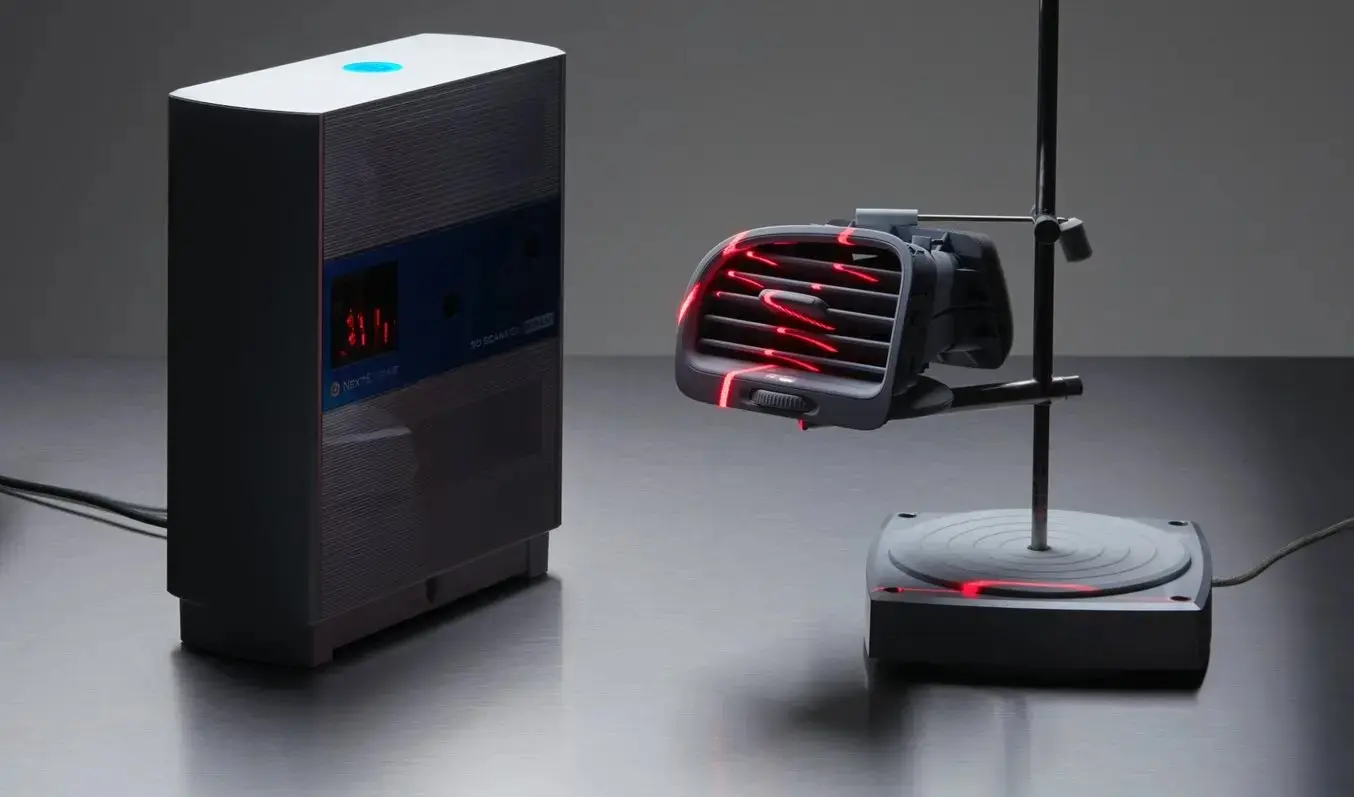
Scanner Holder
Company: Deutsche Bahn
At Deutsche Bahn, employees in materials management needed a way to mount handheld scanners, so they could keep them close by without continuously occupying one of their hands. The team created three different mounts that can be attached to a bag, a belt, or a shadow board. These SLS 3D printed handheld scanner holders make the employee's operations faster and more efficient.
Conclusion
Modern factories must be continuously adapt to changing customer requirements and find new ways to remain efficient, nimble, and competitive. Bringing a product to market involves a multiplicity of processes, machines, and labor that need to be optimized through manufacturing chains. In-house 3D printed aids are used by businesses around the world to help address problems on the shop floor, boosting and streamlining efficiency at every manufacturing step.
From machining workholding devices to assembly jigs, inspection fixtures, or spare parts for end-of-arm tooling, replacing metal tools with 3D printed manufacturing aids on-demand improves the speed, quality, and efficiency of production.
Request a free sample part to see Formlabs’ 3D printed materials firsthand and contact our 3D printing specialists to find the right solution for your application.