WHITE PAPER
Formlabs Logo

Replacing the Fuse Sift sifter flange

Replacing the Fuse Sift sifter flange

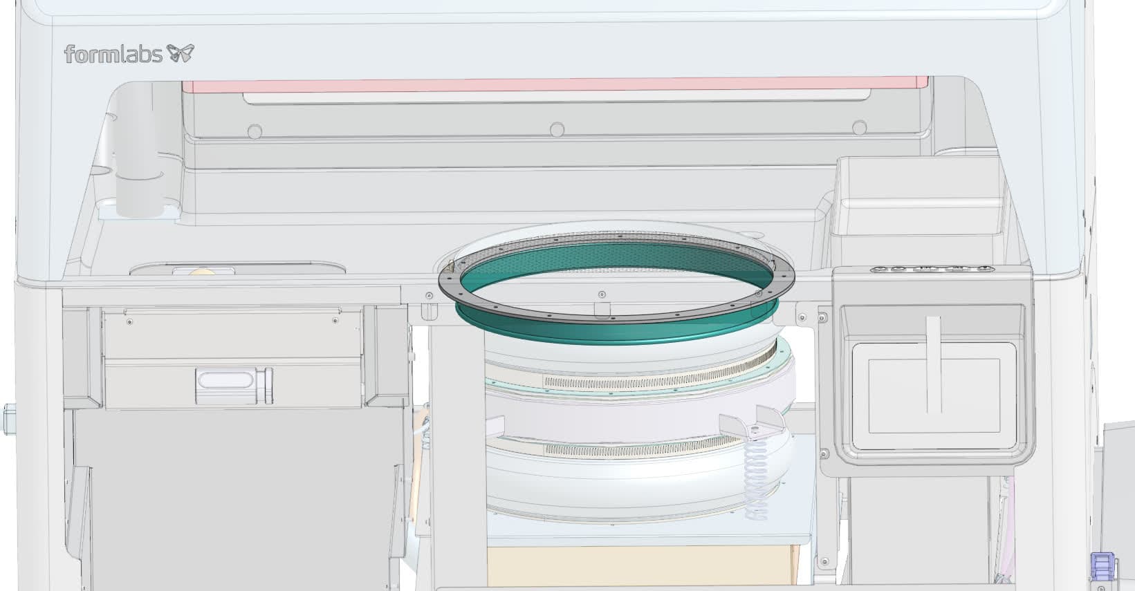
The Fuse Sift sifter flange secures the bellows above the used powder hopper. If the flange is faulty or damaged, powder may leak past the bellows and fall into or below the machine. If the rivets that secure the flange to the machine come loose, the sifter mechanism will vibrate in unexpected ways, leading to noisy operation and potential damage.

Use this guide to replace the Fuse Sift sifter flange.

Fuse Sift sifter rework kit

Required Supplies:

Formlabs:

Third-party:

  • 2.5 mm hex driver (flat-end)
  • 6.0 mm hex driver
  • 6.5 mm slotted screwdriver
  • 3.5 mm (#28) drill bit
  • Drill
  • 1.3 Nm torque screwdriver with 2.0 mm hex bit
  • 12.5 Nm torque screwdriver with 6.0 mm hex bit
  • Flashlight
  • Tape
  • Compliant vacuum with static dissipative components, such as a Class II, Division 2 vacuum
  • Vacuum brush tools
  • Appropriate personal protective equipment for the powder in use, as defined in the safety data sheet (SDS)
  • Nonreactive nitrile gloves
  • Loctite 243 or equivalent threadlocker
Estimated time: 45–60 minutes

Preparing the workspace

Overview: Prepare the Fuse Sift and your workspace for replacing the sifter flange and gasket.

Step 1: Remove and store printed parts

Remove any printed parts from the Fuse Sift workspace to prevent them from being damaged inadvertently.

Step 2: Clean the workspace

Using the vacuum attached to your Fuse Sift, clean the workspace. Vacuum any loose powder inside the workspace, under the hood, on the print bed and the surrounding port, and on the vent filter.

Step 3: Clean below the surface grate

Cleaning the Fuse Sift

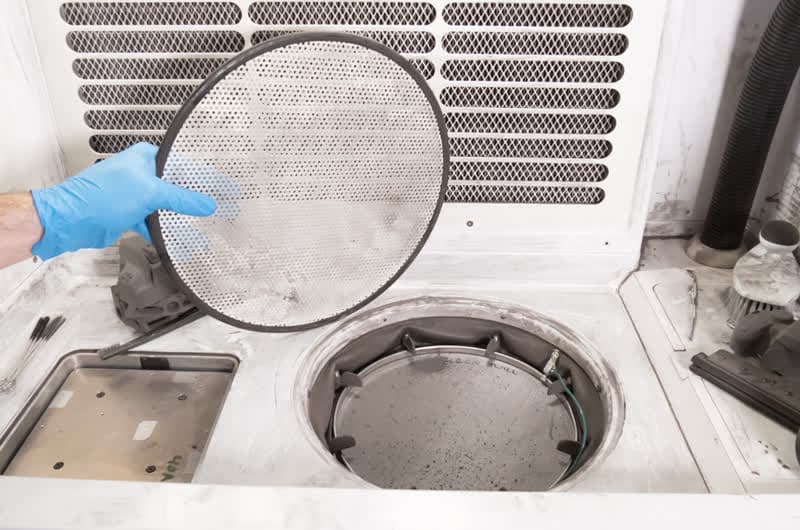
Remove the sifter surface grate from the workspace to expose the sifter mesh. Set the sifter surface grate aside.

Vacuum all powder and debris on top of and around the sieve and the sifter frame. After vacuuming, ensure that the sieve is properly secured onto the sifter by all eight turnbuckles.

Step 4: Unplug the Fuse Sift

Power off the Fuse Sift, then unplug the power cable from the rear panel.

Danger:

Performing this procedure on the Fuse Sift while it is plugged in increases the risk of electric shock. After disconnecting the power from the Fuse Sift, wait at least five minutes before servicing.

Step 5: Unscrew the Wi-Fi antenna

Remove the Wi-Fi antenna, if present.

Warning:

Use appropriate personal protective equipment when handling loose or unsintered powder. Refer to the support article Safety with Formlabs SLS products or your powder’s safety data sheet (SDS) for more information.

Removing the upper front enclosure panel

Overview: Remove the upper front enclosure panel to begin accessing the sifter flange.

Step 1: Unscrew the upper front enclosure panel mounting screws

Remove the upper front enclosure panel

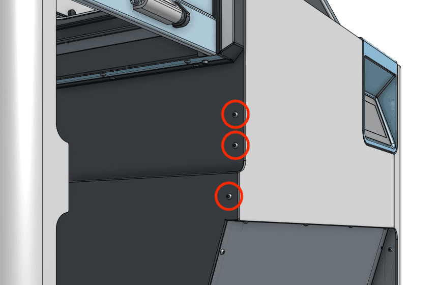
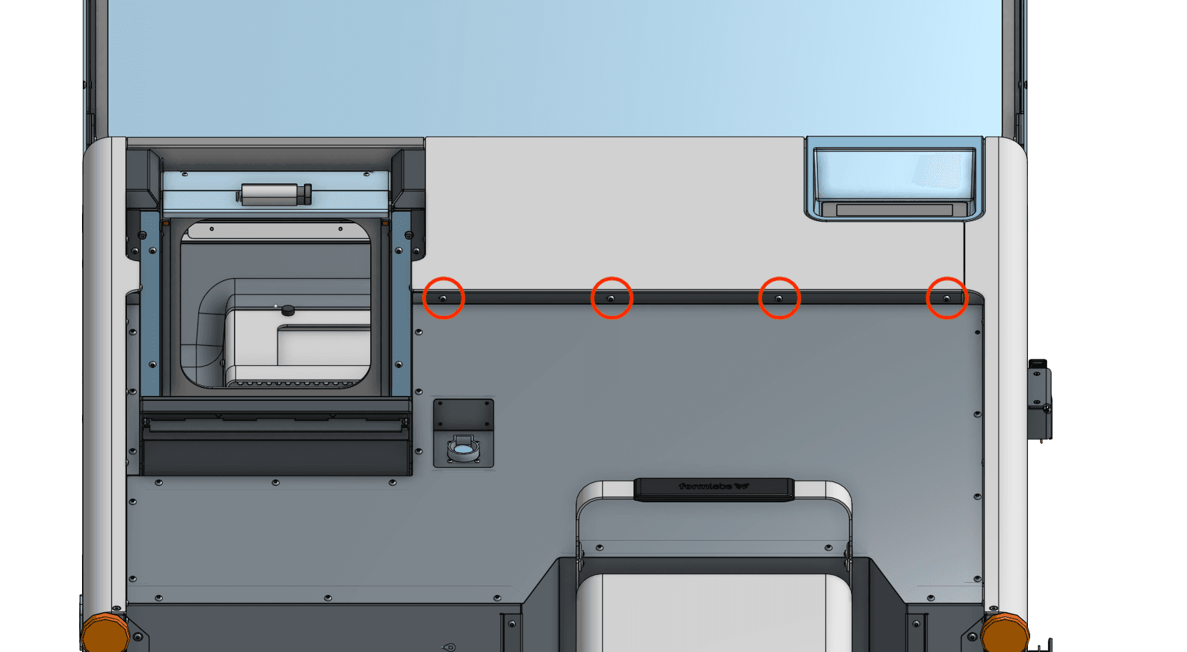
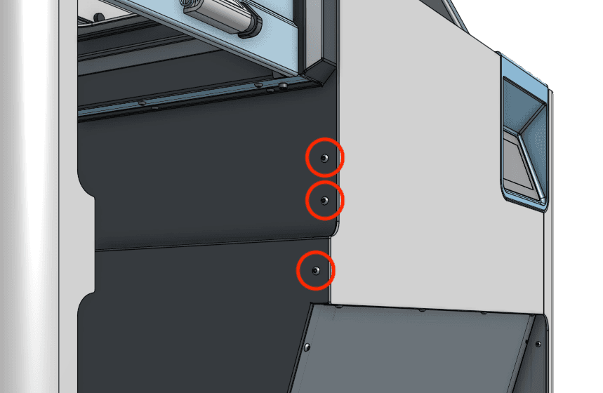
Using a 2.5 mm hex driver, loosen and remove the four black 8.0 mm M4 button screws underneath the upper front enclosure panel lip. Remove the three black 8.0 mm M4 button screws from the left-hand side of the same panel. Set the screws aside.

Step 2: Remove the upper front enclosure panel

Slide the panel downwards to remove it from the Fuse Sift. Set the upper front enclosure panel aside.

Removing the rear enclosure panel

Overview: Separate the rear enclosure panel from the Fuse Sift in order to access the vibration motor.

Step 1: Unscrew the rear enclosure panel mounting screws

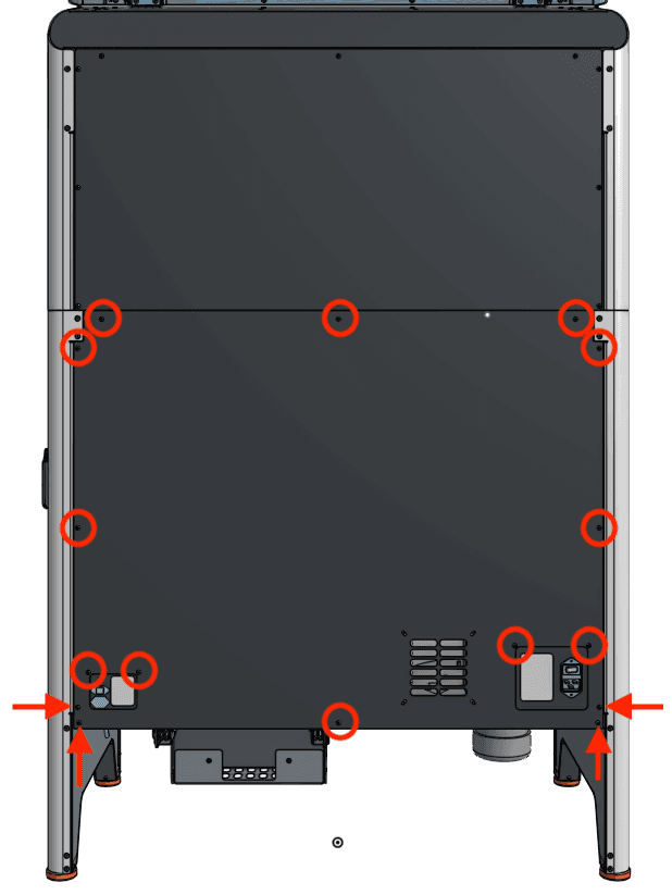
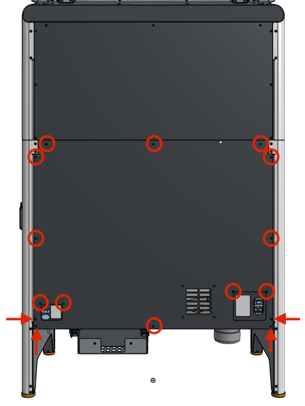
Use a 2.5 mm hex driver to remove the 16 black 8.0 mm M4 screws securing the rear panel to the Fuse Sift. Set the screws aside.

Step 2: Remove the rear closure panel

Separate the rear enclosure panel from the Fuse Sift and set it aside.

Remove the rear enclosure panel

Detaching the vibration motor

Overview: Detach the vibration motor from the sifter assembly in order to remove the sifter flange.

Step 1: Unscrew the vibration motor mounting screws

Detach the vibration motor

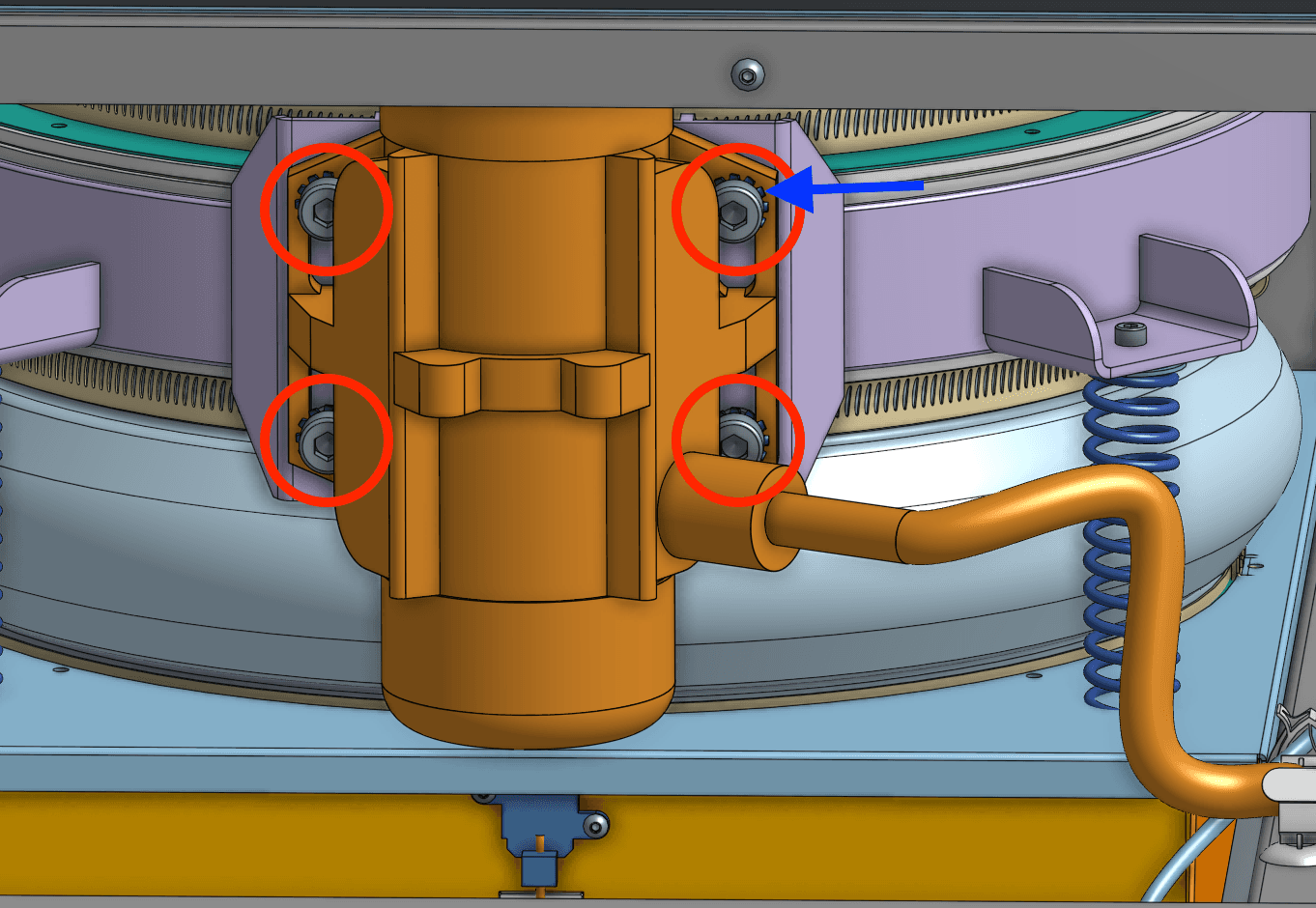
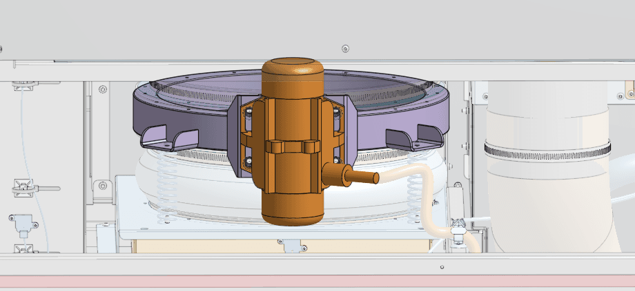
Locate the vibration motor, positioned on the back of the sifter assembly. Using a 6.0 mm hex driver, loosen and remove the four 20.0 mm M8 cap screws and lock washers securing the motor. Set the screws and lock washers aside.

You may need to use a ball-end hex driver or loosen the vibration motor cable gland to access all four screws.

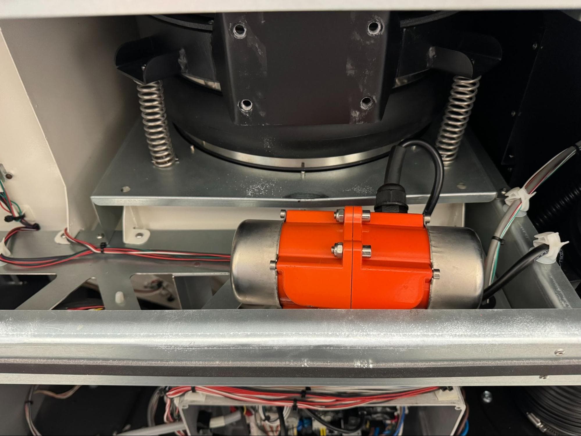
Place the motor horizontally on the upper shelf assembly.

Removing the existing sifter flange and gasket

Overview: Drill out the rivets that secure the sifter flange to the Fuse Sift and remove it from the machine.

Step 1: Locate the sifter flange rivets

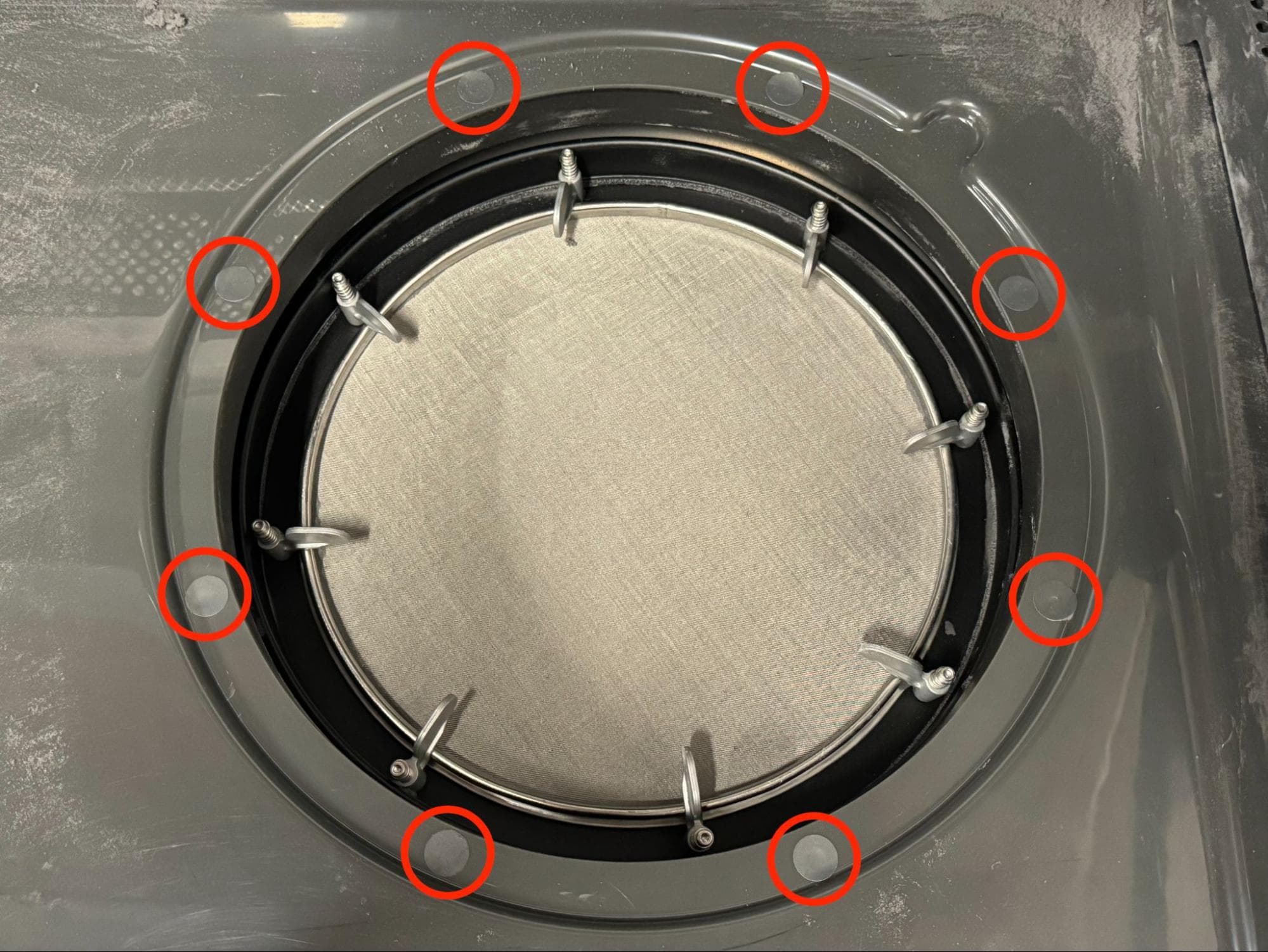
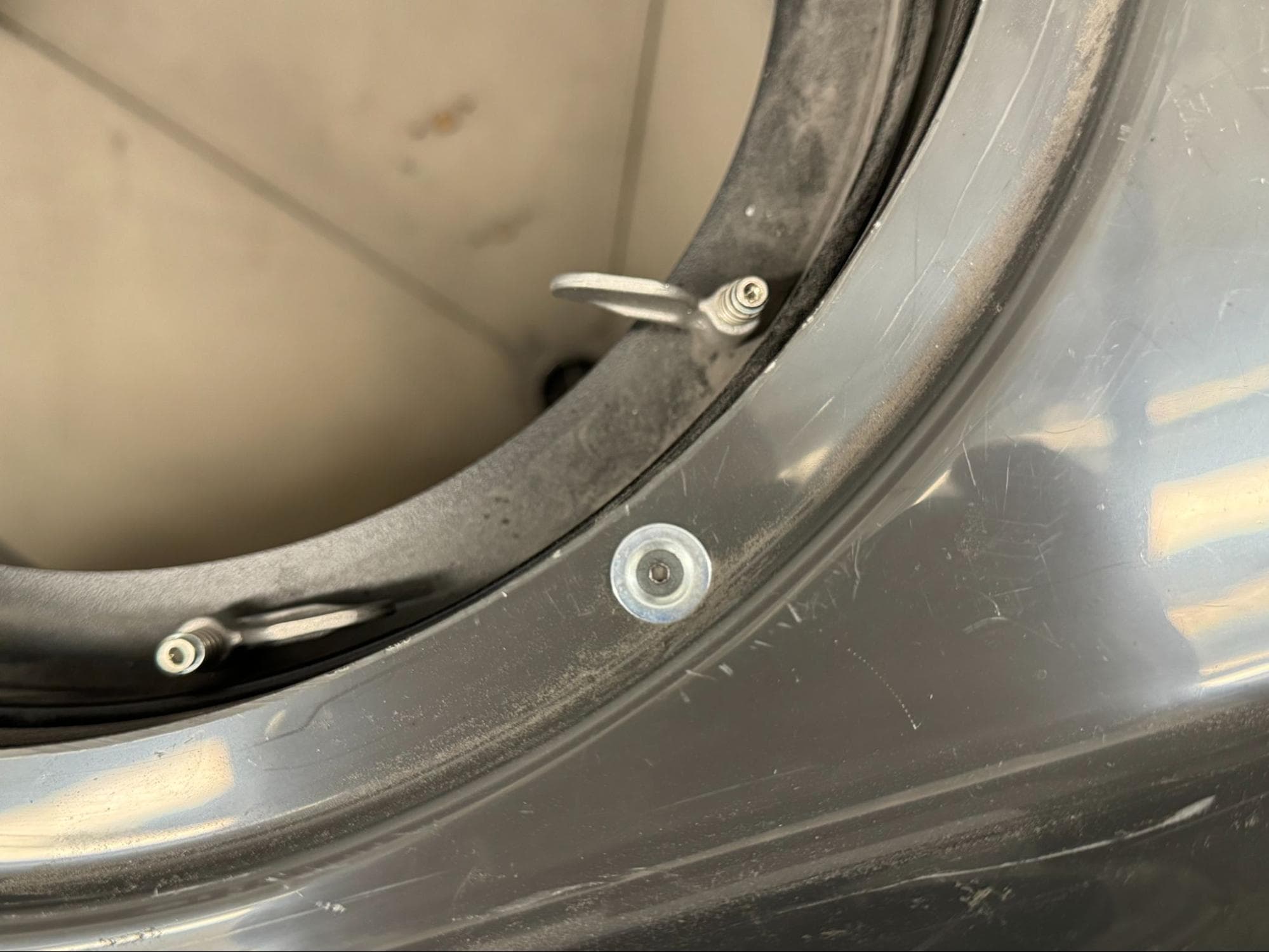
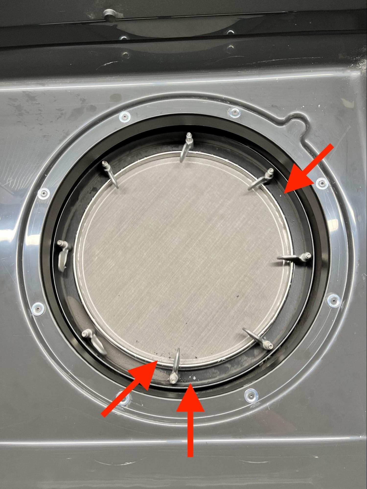
Locate and remove the eight grey stickers applied to the work surface around the sifter. These stickers cover a set of rivets.

Remove the existing sifter flange & gasket

Step 2: Drill out the sifter flange rivets

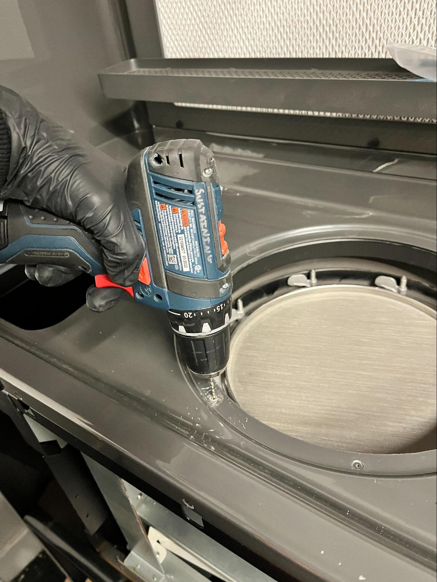
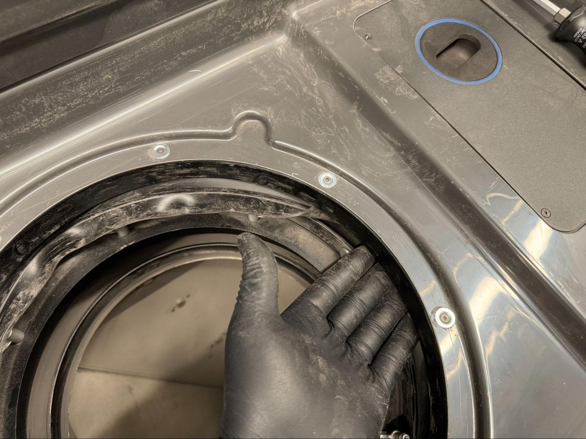
Using a drill with a 3.5 mm (#28) drill bit, drill out the rivets. Bore through the center of each rivet while pushing downward on the back of the drill. If a rivet begins spinning in the work surface, try gripping it from below with pliers.

The rivets may remain in the existing sifter flange, so long as they are disengaged from the work surface. The sifter flange will sink into the sifter once all eight rivets have been drilled out.

Remove the existing sifter flange & gasket

Step 3: Separate the upper sifter bellows from the sifter flange

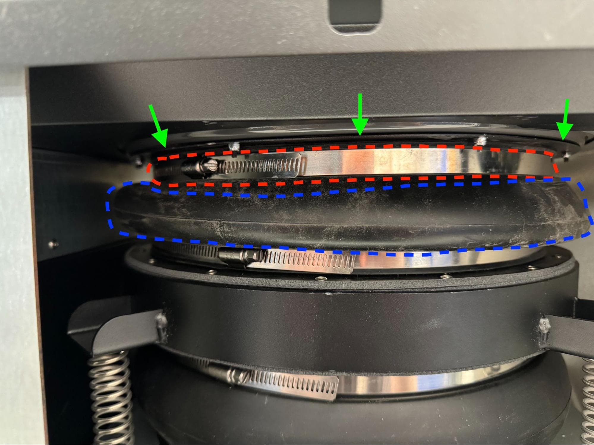
Use a 6.5 mm slotted screwdriver to completely open and unlink the hose clamp securing the upper sifter bellows to the existing sifter flange. Remove the hose clamp from the machine and set it aside. Gently pull the upper sifter bellows down and away from the existing sifter flange.

Remove the existing sifter flange & gasket

Step 4: Remove the sifter flange and gasket

Remove the existing sifter flange & gasket

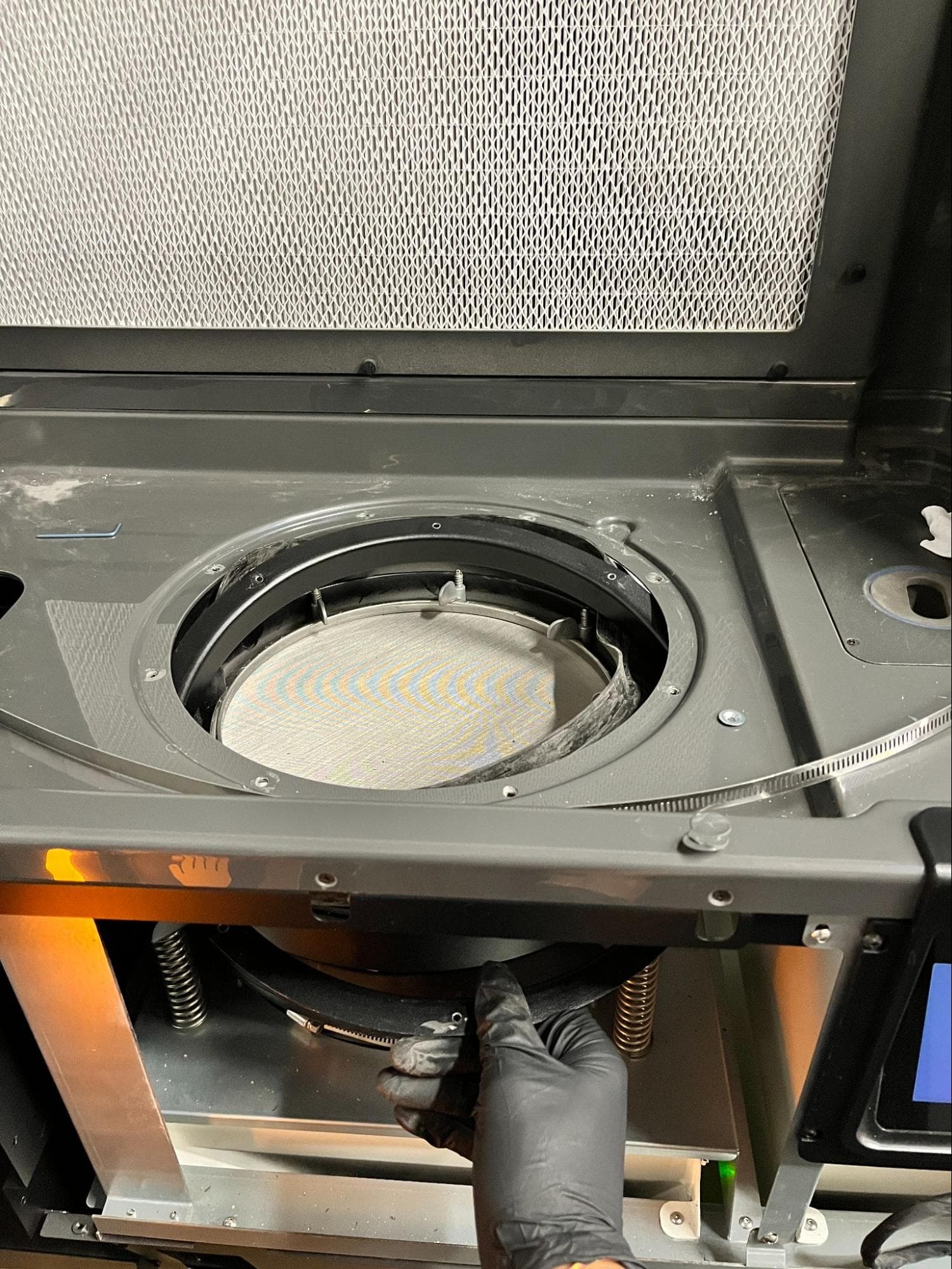
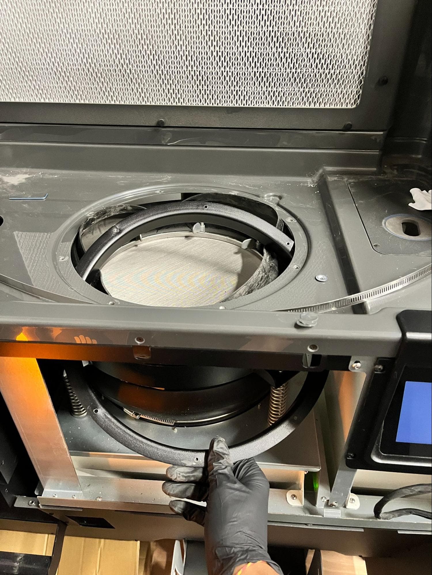
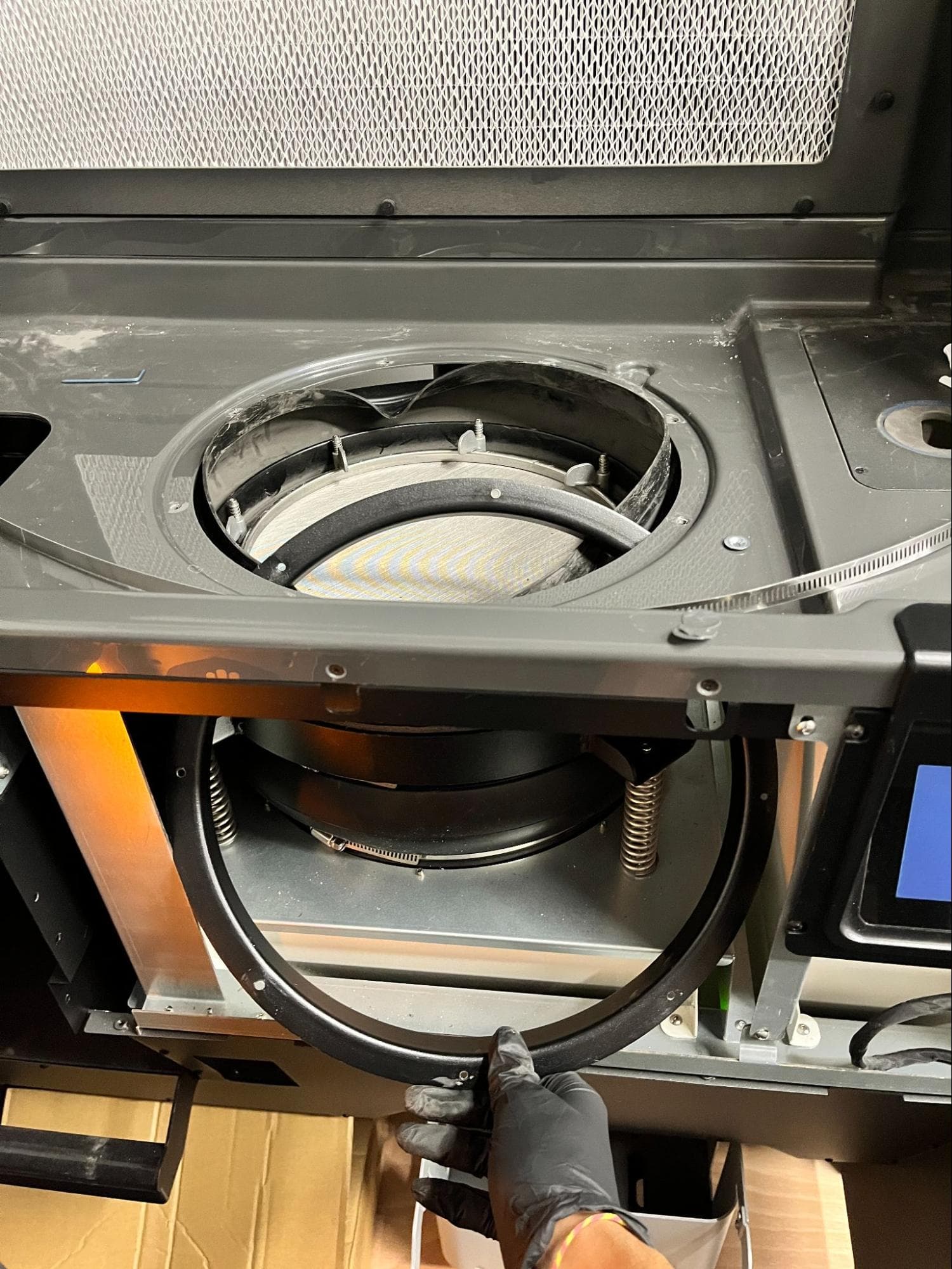
Carefully remove the existing sifter flange through the clearance at the front of the machine. Avoid gouging, tearing, or puncturing the upper sifter bellows while removing the existing sifter flange. If the sifter flange gasket does not come out with the sifter flange, pull it out as well.

Set the sifter flange and gasket aside for disposal.

Installing the replacement sifter flange and gasket

Overview: Mount and secure the replacement sifter flange and gasket using the jig and fasteners included in the sifter rework kit.

Step 1: Check the sifter rework kit

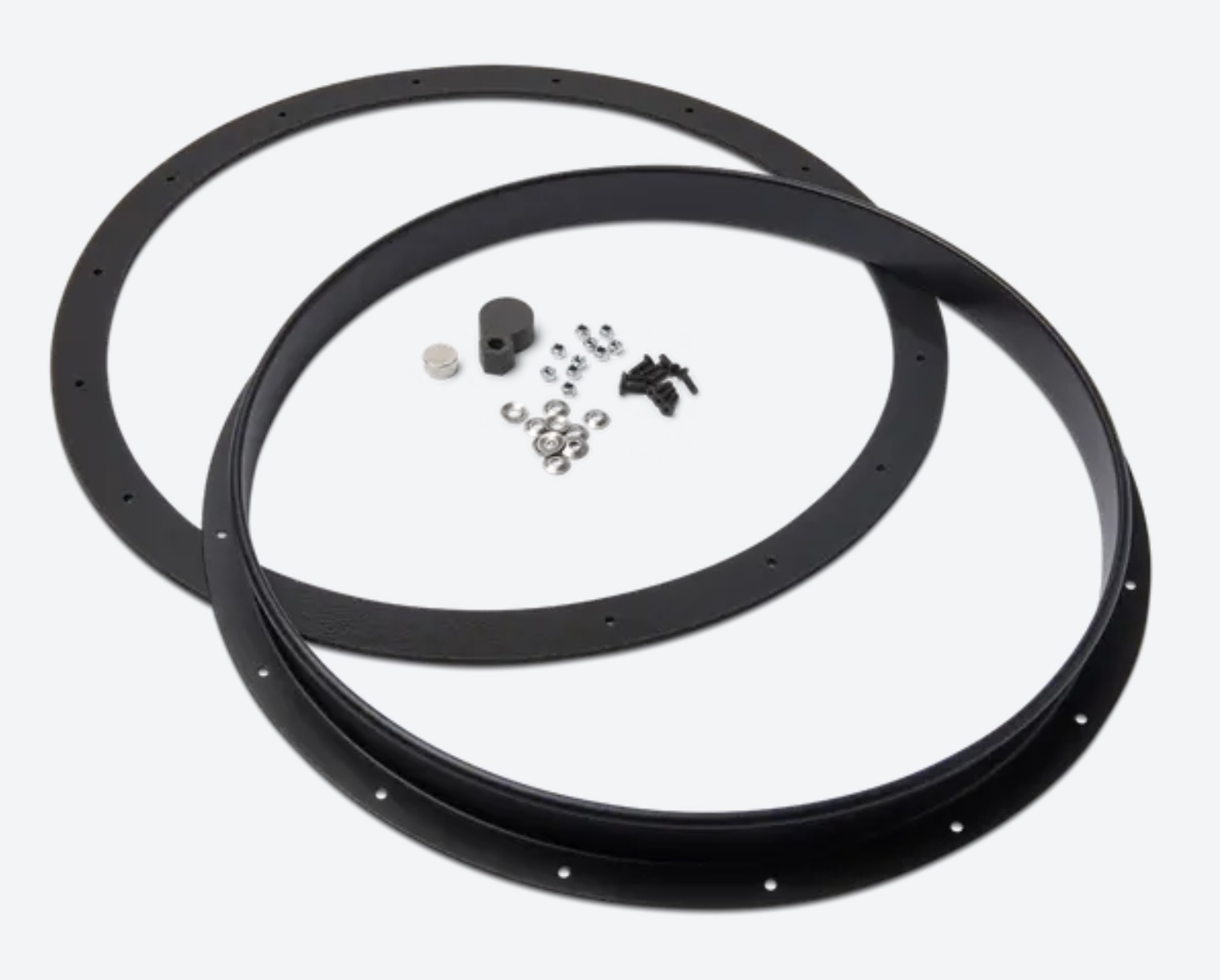
Unpack the sifter rework kit and ensure that the following items are present:

  • Replacement sifter flange
  • Replacement sifter flange gasket
  • SLS-printed jig
  • Disc magnet
  • Countersunk stainless steel washers, 10x
  • M3 lock nuts, 10x
  • 10.0 mm M3 countersunk screws, 10x

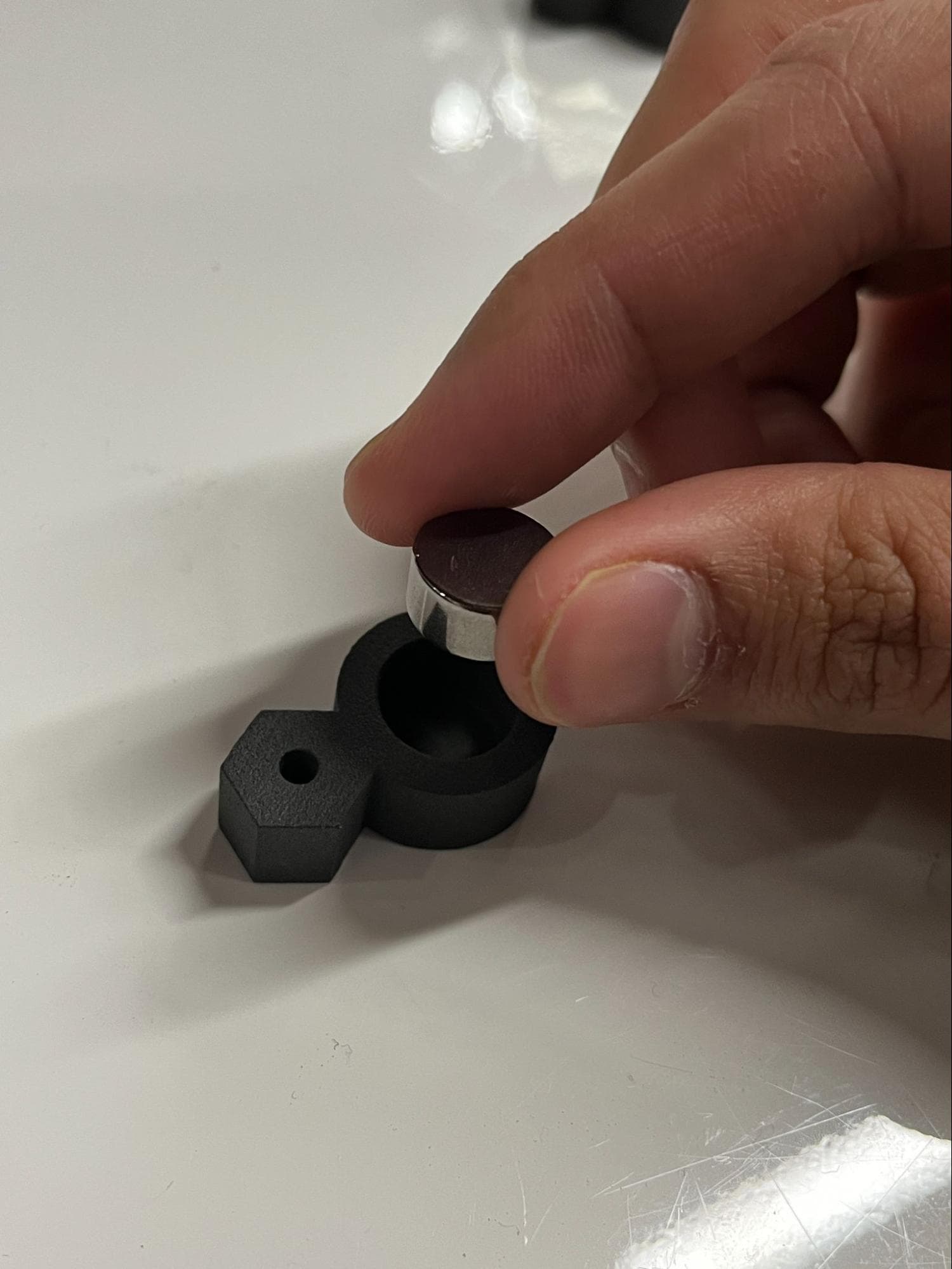
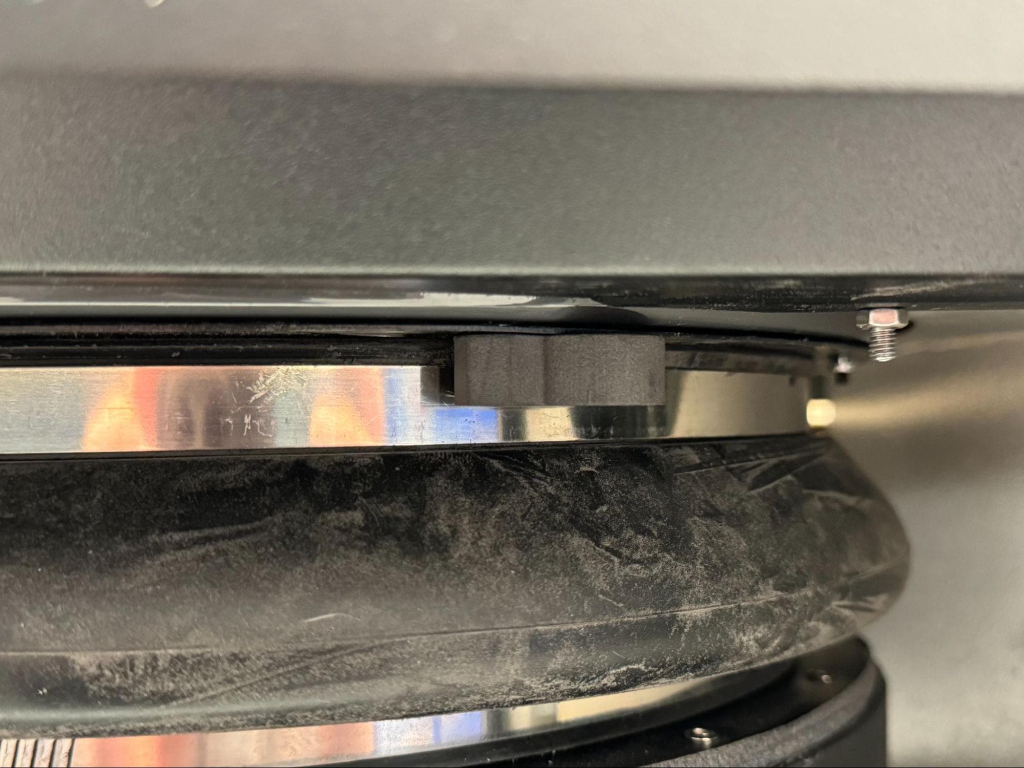
Press the disc magnet into the larger pocket of the SLS-printed jig. If it does not stay in place, tape it to the jig.

Install the new sifter flange & gasket

Step 2: Mount the gasket

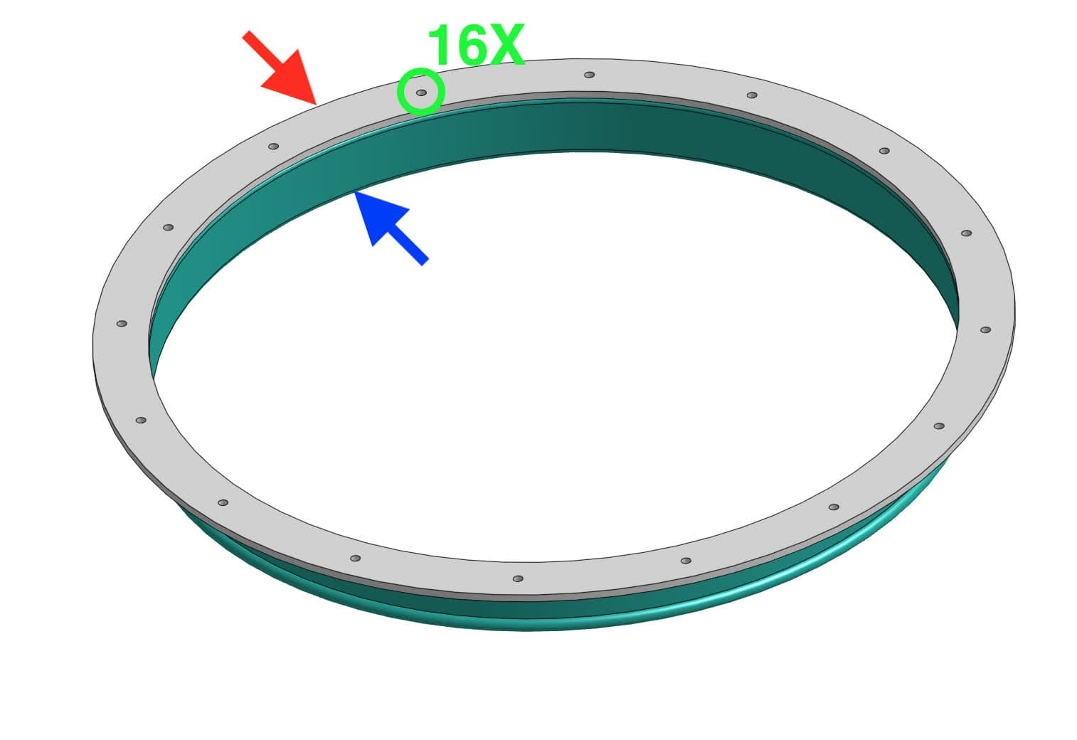
Place the replacement flange gasket onto the replacement sifter flange, ensuring that the 16 holes in the gasket align with the 16 holes in the flange. Note that the gasket does not adhere in place, so you may need to readjust it as you work to keep the holes aligned.

Install the new sifter flange & gasket

Step 3: Prepare a sifter flange and gasket mounting screw

Locate the front-most counterbore at the 5 o’clock position in the work surface. Place one countersunk washer into the couterbore, followed by a 10.0 mm M3 countersunk screw.

Install the new sifter flange & gasket

Step 4: Mount the softer flange and gasket

Bring the new sifter flange and gasket into the machine with the gasket facing up. Orient it so that the M3 screw sticking through the work surface passes through the aligned clearance holes in the new sifter flange and gasket.

Install the new sifter flange & gasket

Step 5: Begin securing the sifter flange and gasket

Thread one lock nut onto the M3 screw by hand. Take the jig and place the hex pocket over the lock nut. Rotate the jig towards the sifter flange until the magnet holds the jig in place.

From the top of the work surface, use a 2.0 mm hex driver to fully thread the M3 countersunk screw into the lock nut below. You may find it helpful to have a second person hold the jig in place or press the flange upwards against the work surface. Remove the jig from the machine once the screw is tightened.

Install the new sifter flange & gasket

Step 6: Continue securing the sifter flange and gasket

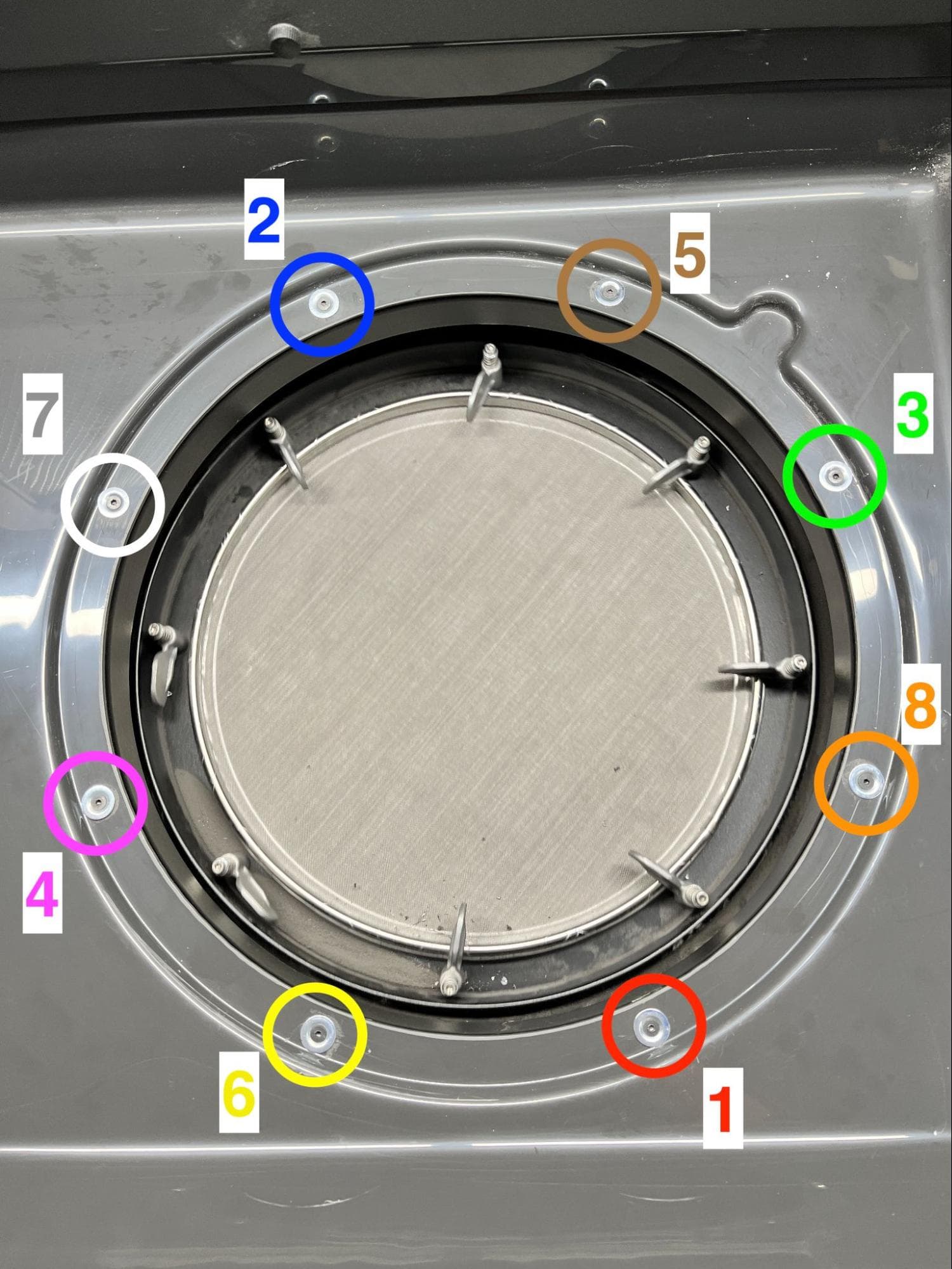
Repeat steps 3–5 for the remaining seven sifter flange mounting points in the order depicted here.

Step 7: Fully torque the sifter flange mounting screws

Using a 1.3 Nm torque screwdriver with a 2.0 mm hex bit, torque all eight screws in the order depicted here.

Install the new sifter flange & gasket

Step 8: Mount the upper sifter bellows onto the sifter flange

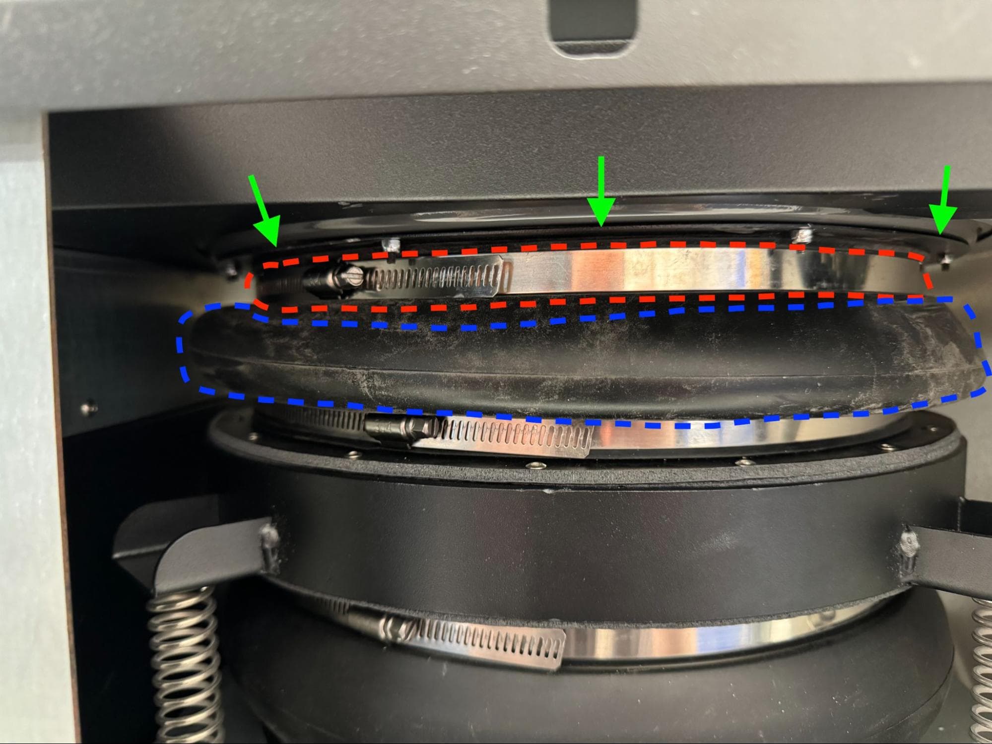
Begin sliding the lip of the upper sifter bellows onto the sifter flange. Start at the front of the machine, then work the lip of the upper sifter bellows into position through the sifter clearance hole in the work surface.

Install the new sifter flange & gasket

Step 9: Place the hose clamp around the upper bellows

Open the hose clamp and feed it around the upper sifter bellows from the rear of the machine. Go to the front of the machine and use a 6.5 mm slotted screwdriver to feed the hose clamp band into the hose clamp’s screw cage until the clamp is loosely secure around the flange and the top of the bellows.

Step 10: Check the position of the upper sifter bellows and hose clamp.

Install the new sifter flange & gasket

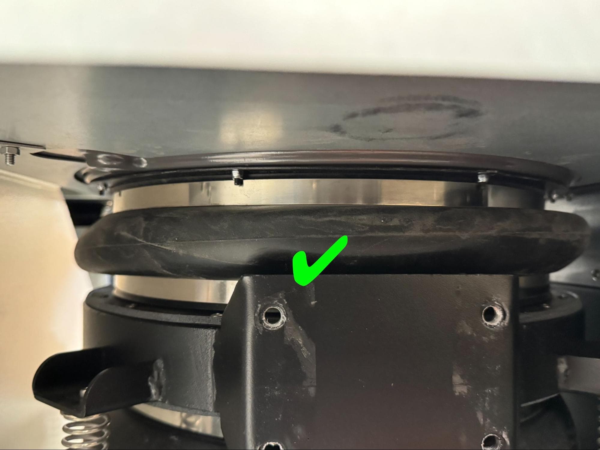
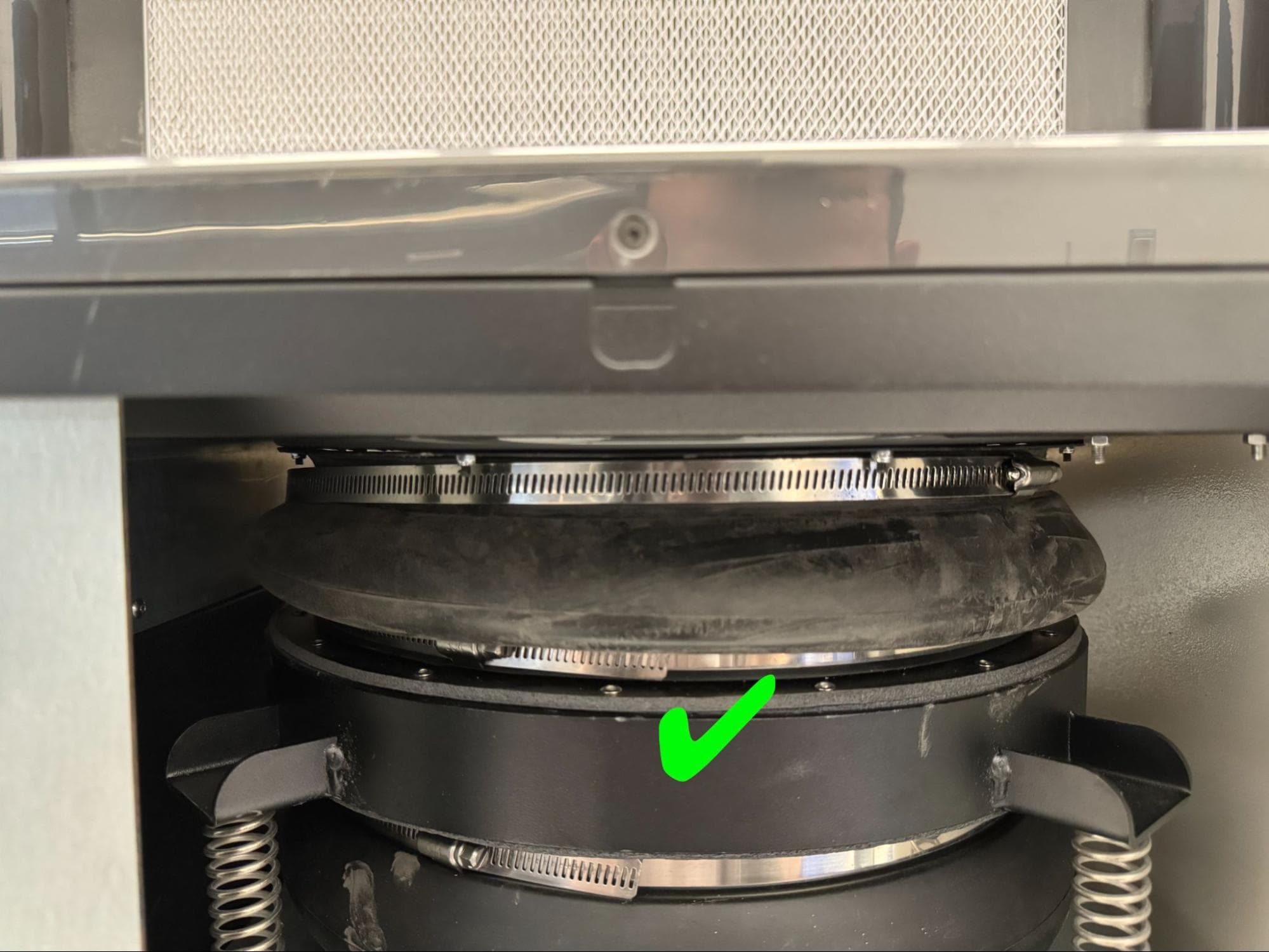
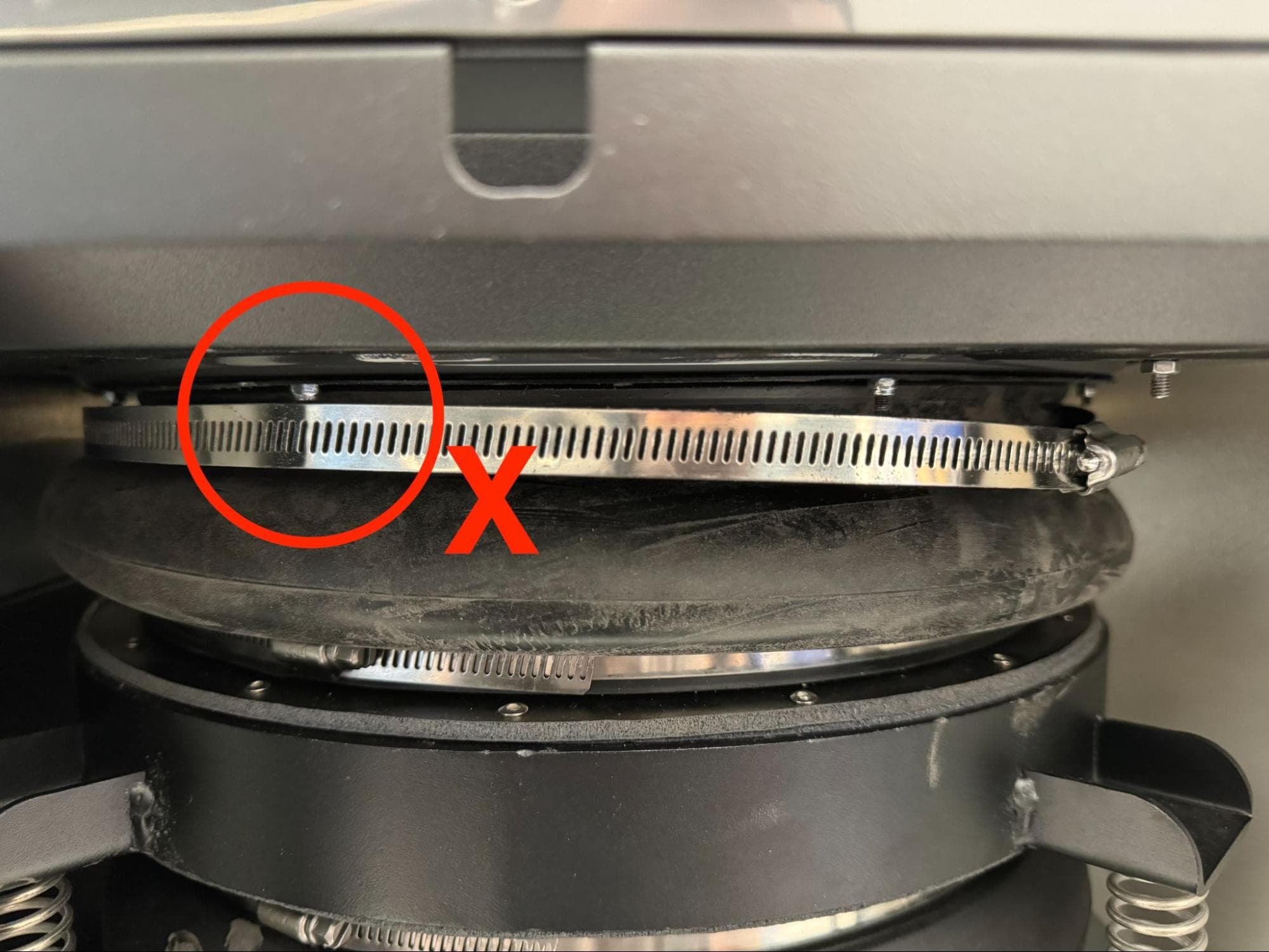
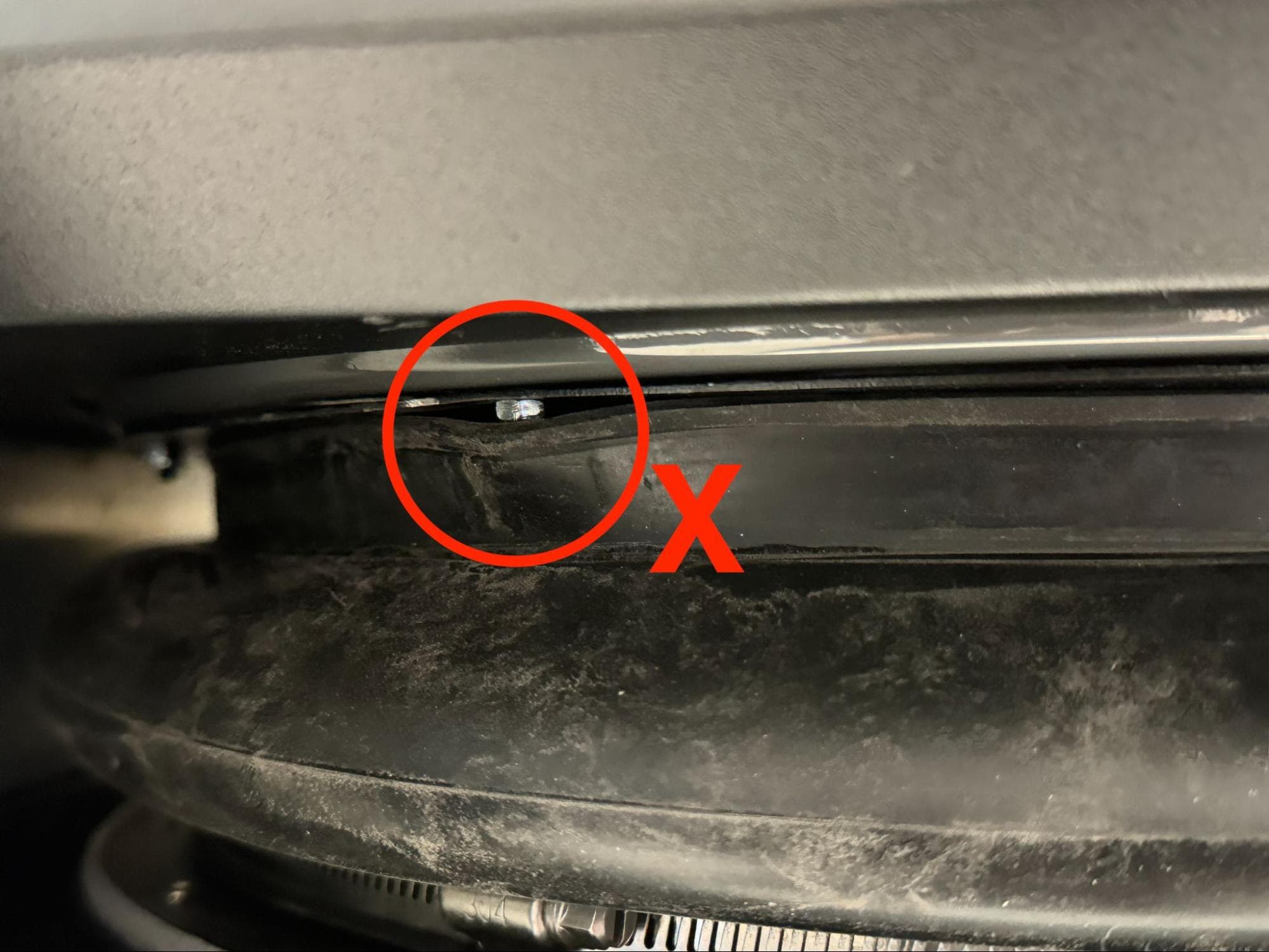
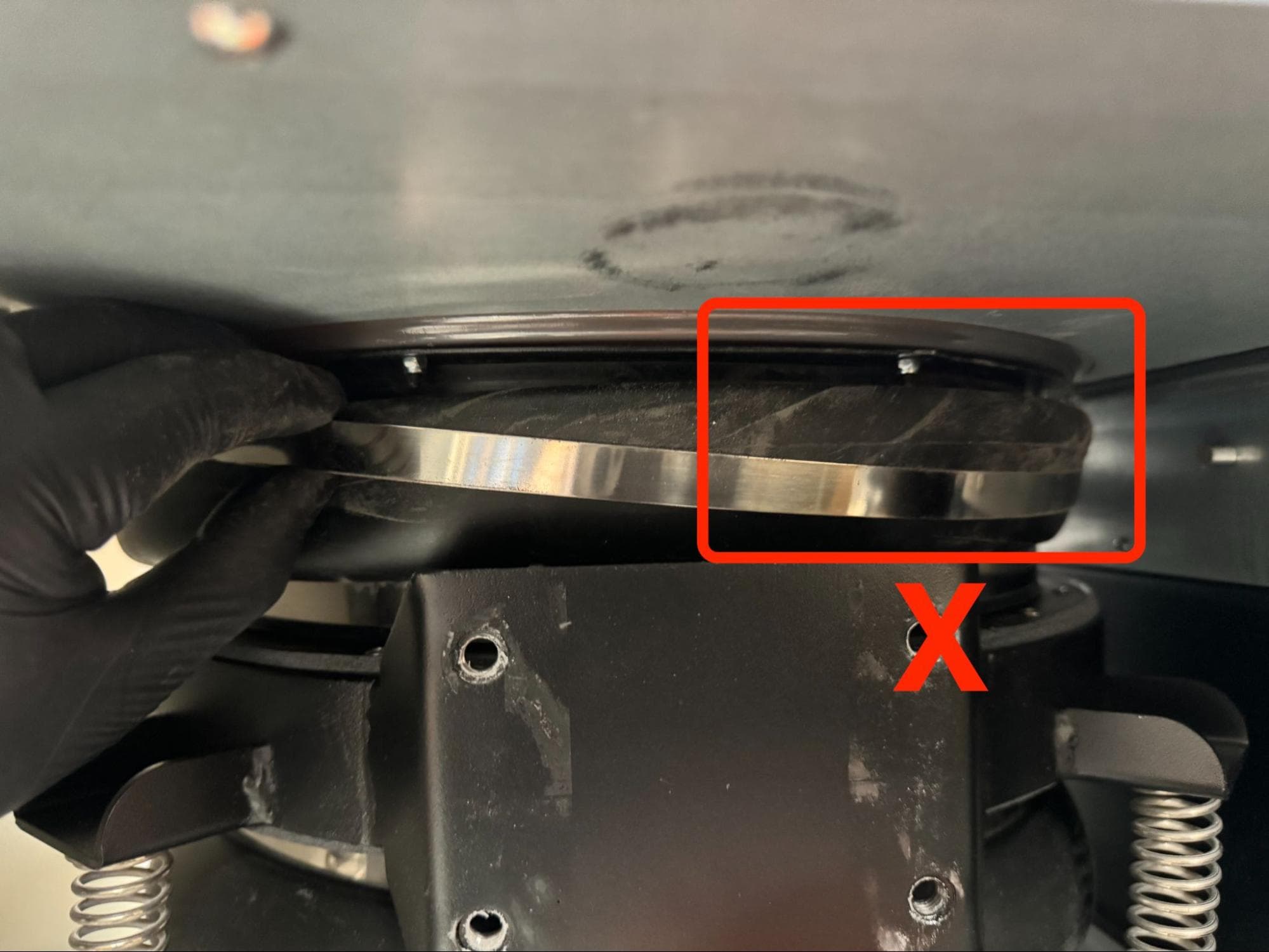
Confirm that the upper sifter bellows and hose clamp are concentrically aligned with the sifter flange. Make sure that there are no kinks or creases where the bellows lip contacts the sifter flange and that neither the upper sifter bellows lip nor hose clamp band are caught on the protruding M3 screws.

Step 11: Secure the upper sifter bellows

Use a 6.5 mm slotted screwdriver to close the hose clamp as much as possible and secure the upper sifter bellows to the sifter flange.

Install the new sifter flange & gasket

Step 12: Clean the work surface

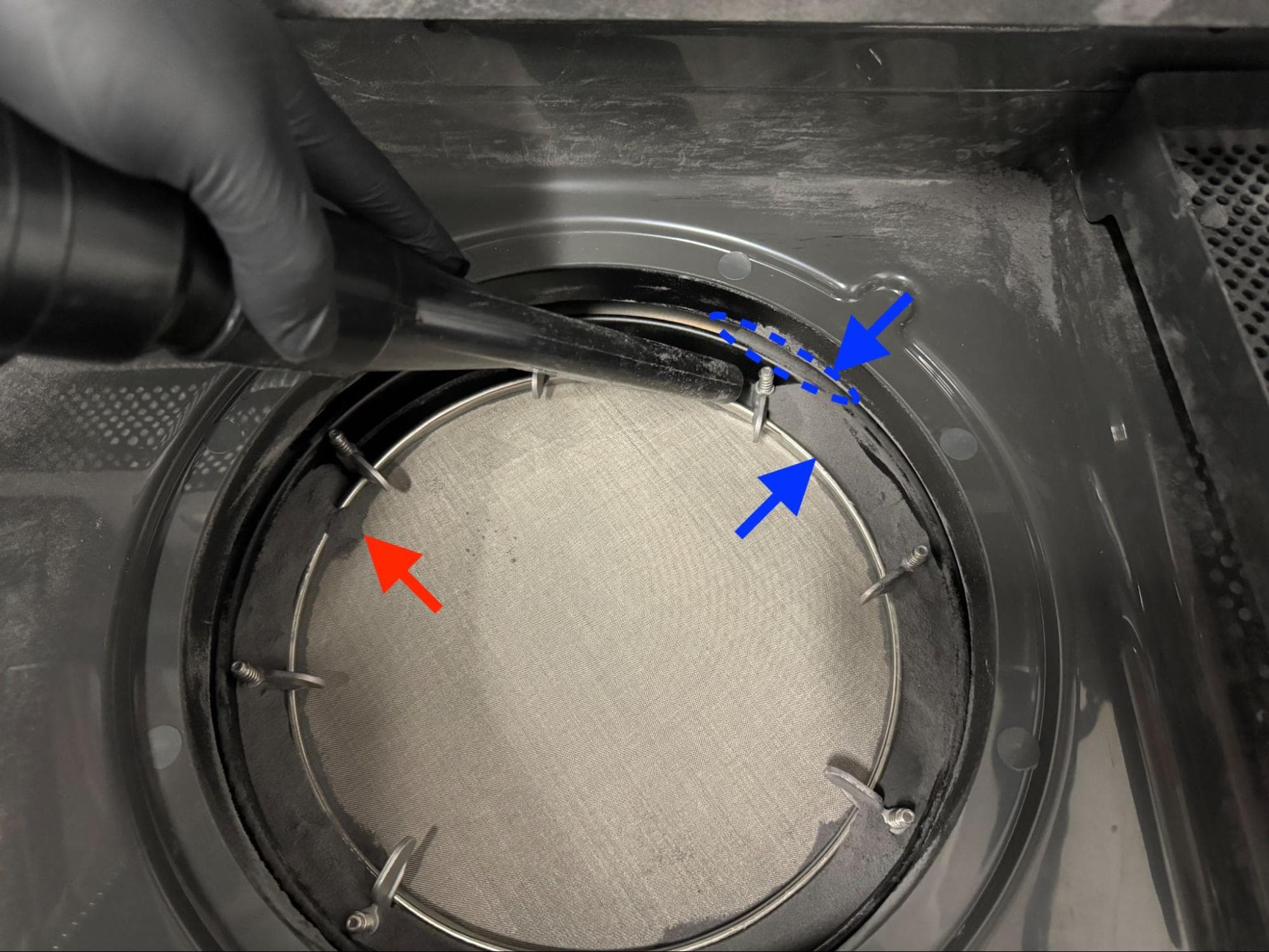
Vacuum any debris on top of and around the sifter mesh, the sifter and the entire work surface that resulted from replacing the sifter flange. Any debris from replacing the sifter flange that is not collected before resuming use of the machine may contaminate your powder or obstruct the Fuse Sift doser assembly.

Install the new sifter flange & gasket

Reinstalling the vibration motor

Overview: Mount and secure vibration motor.

Step 1: Mount the vibration motor

Align the vibration motor with the four M8 taps on the back of the sifter assembly so that the motor’s cable is on the right-hand side.

Install the new vibration motor

Step 2: Secure the vibration motor

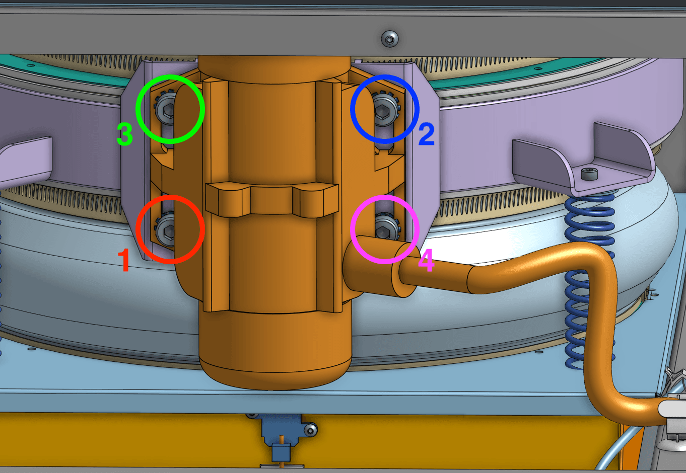
Place one lock washer onto each of the four vibration motor mounting screws. Apply a small dab of Loctite 243 or equivalent threadlocker to the threads of each screw. Thread one screw into each of the four screw holes in the motor and sifter assembly. Use a 6.0 mm hex driver to replace the 4X 20.0 mm M8 cap screws to secure the vibration motor to the sifter assembly.
Step 3: Torque the vibration motor screws

Use a torque screwdriver with a 6.0 mm hex bit to torque each of the vibration motor mounting screws to 12.5 Nm in the order depicted here.

You may need to use a ball-end hex driver or loosen the vibration motor cable gland to access all four screws.

Install the new vibration motor

Reinstalling the rear enclosure panel

Overview: Mount and secure the rear enclosure panel after installing the new sifter flange and gasket.

Step 1: Prepare the rear panel retention screws

Apply a small amount of Loctite 243 or other similar threadlocker to each of the 16 black 8.0 mm M4 button screws that secure the rear panel to the Fuse Sift.

Step 2: Mount the rear panel

Mount the rear panel onto the Fuse Sift.

Step 3: Secure the rear panel

Thread one 8.0 mm M4 button screw into each of the 16 screw holes in the rear panel. Use a 2.5 mm hex driver to tighten until snug.

Replace the rear enclosure panel

Tip:

Start with the top three screws to hold the panel in place while you thread and tighten the remaining screws.

Reinstalling the upper front enclosure panel

Overview: After reinstalling the rear enclosure panel, reinstall the upper front enclosure panel.

Step 1: Align the upper front enclosure panel

Replace the upper front enclosure panel

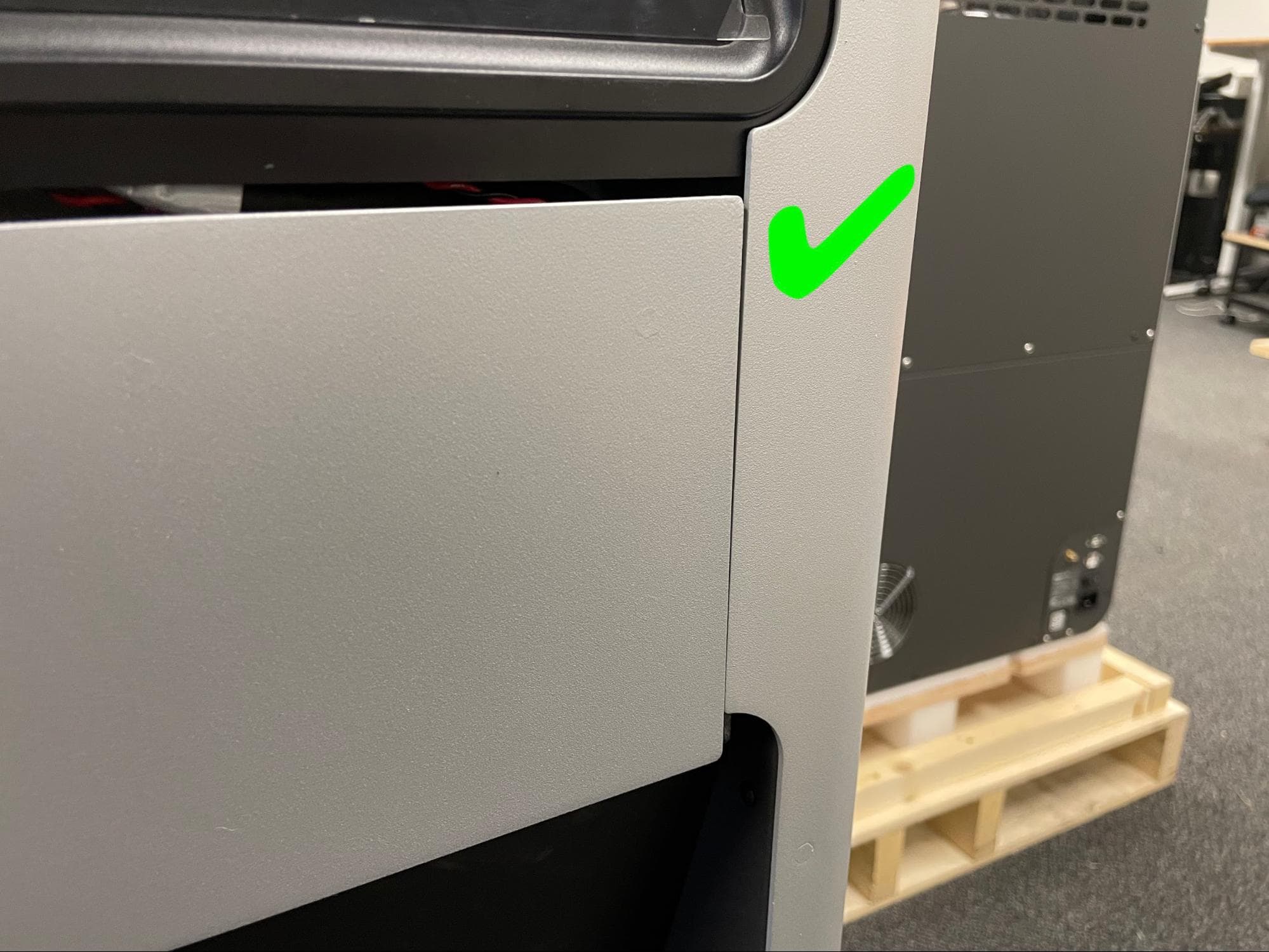
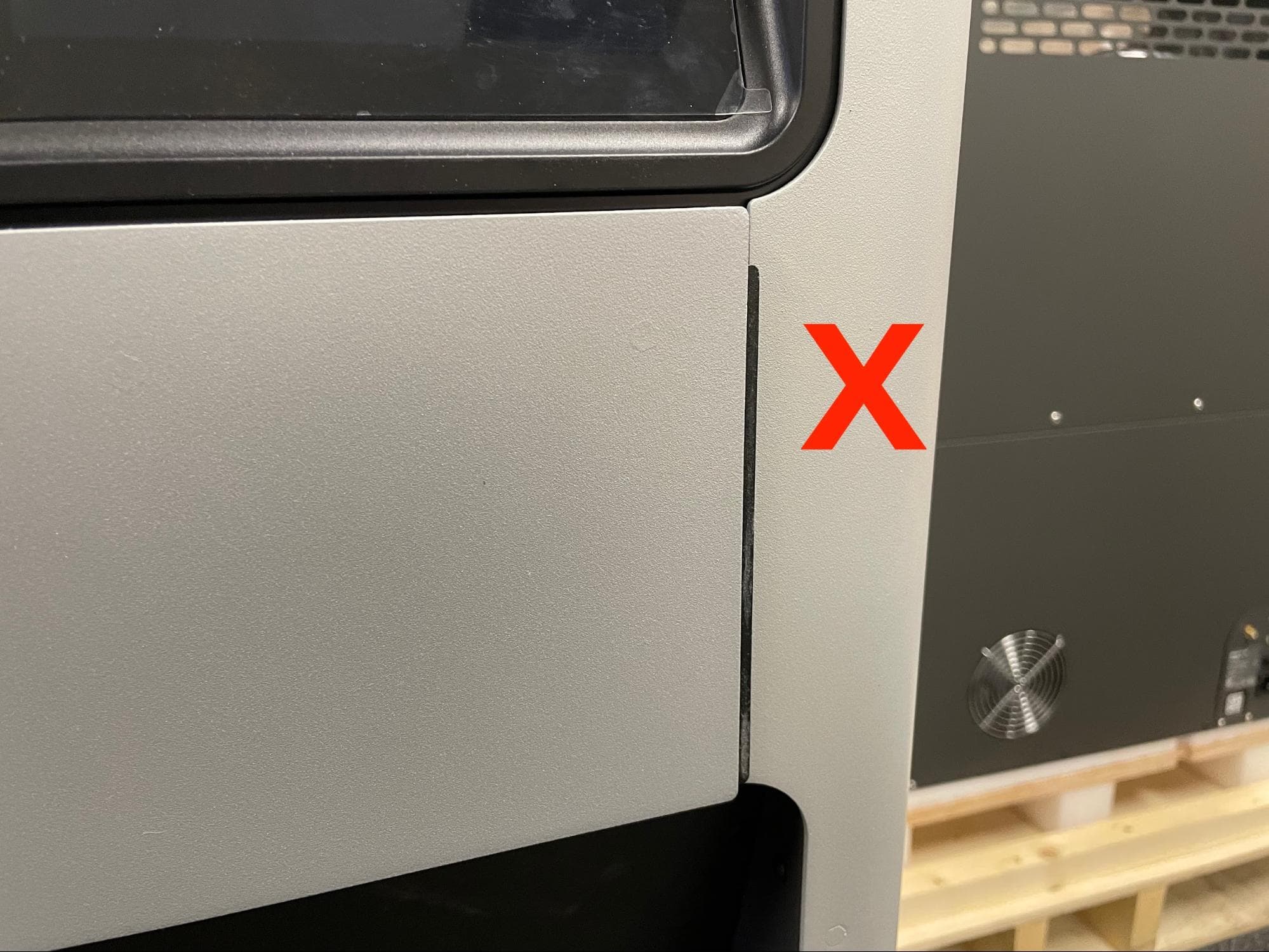
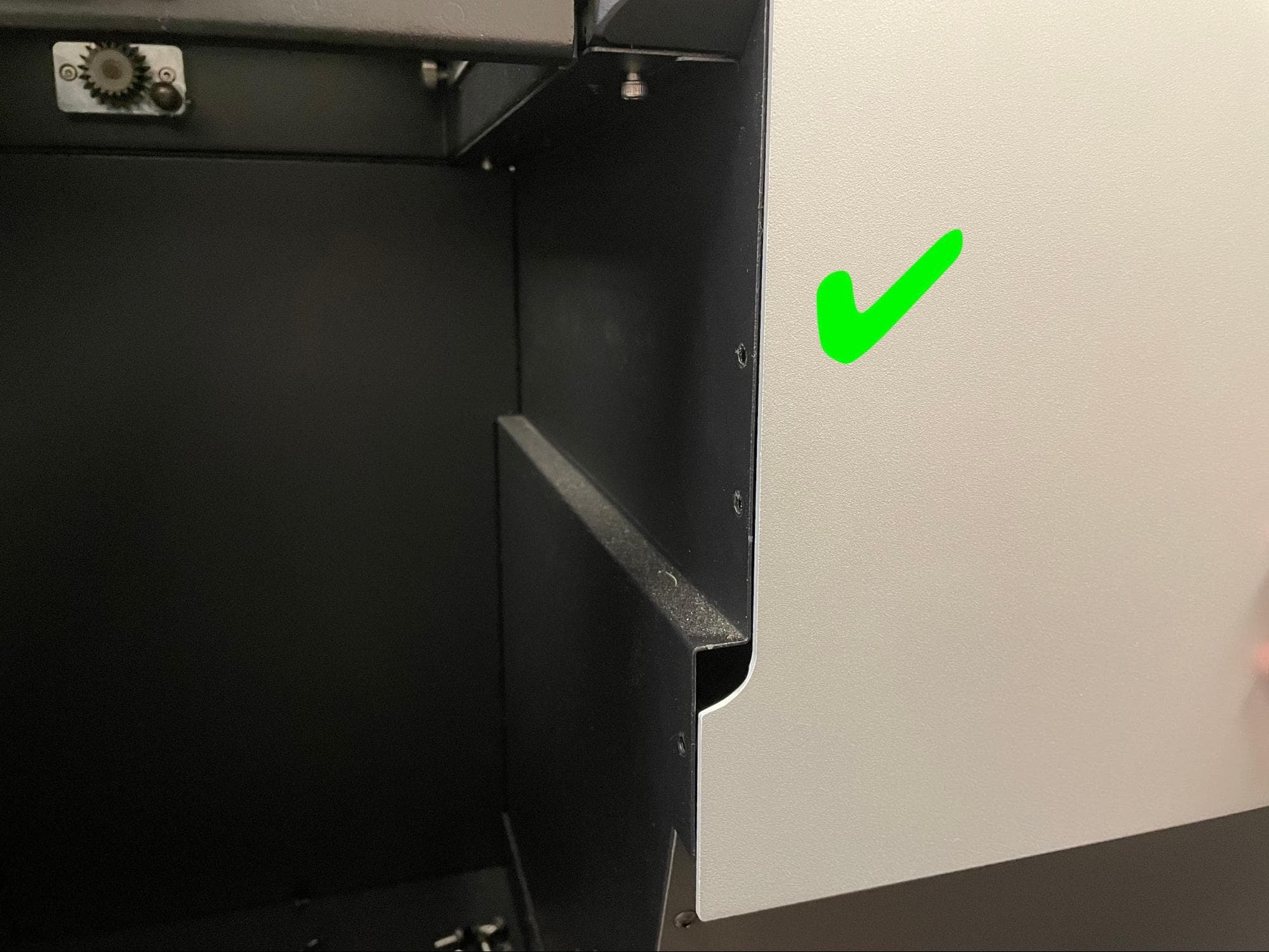
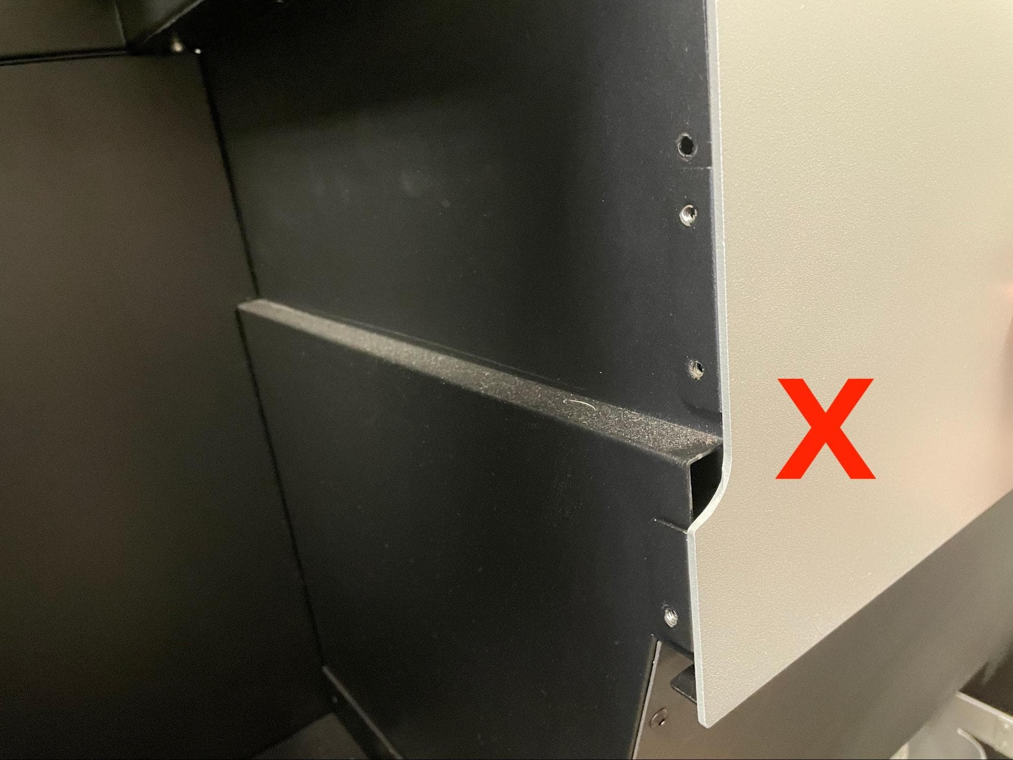
Align the upper front enclosure panel with the so that the black tab on the right-hand side of the panel and the two black flanges on the left-hand side of the panel are not visible. Start by aligning the smaller tab on the right first.

Step 2: Mount the upper front enclosure panel

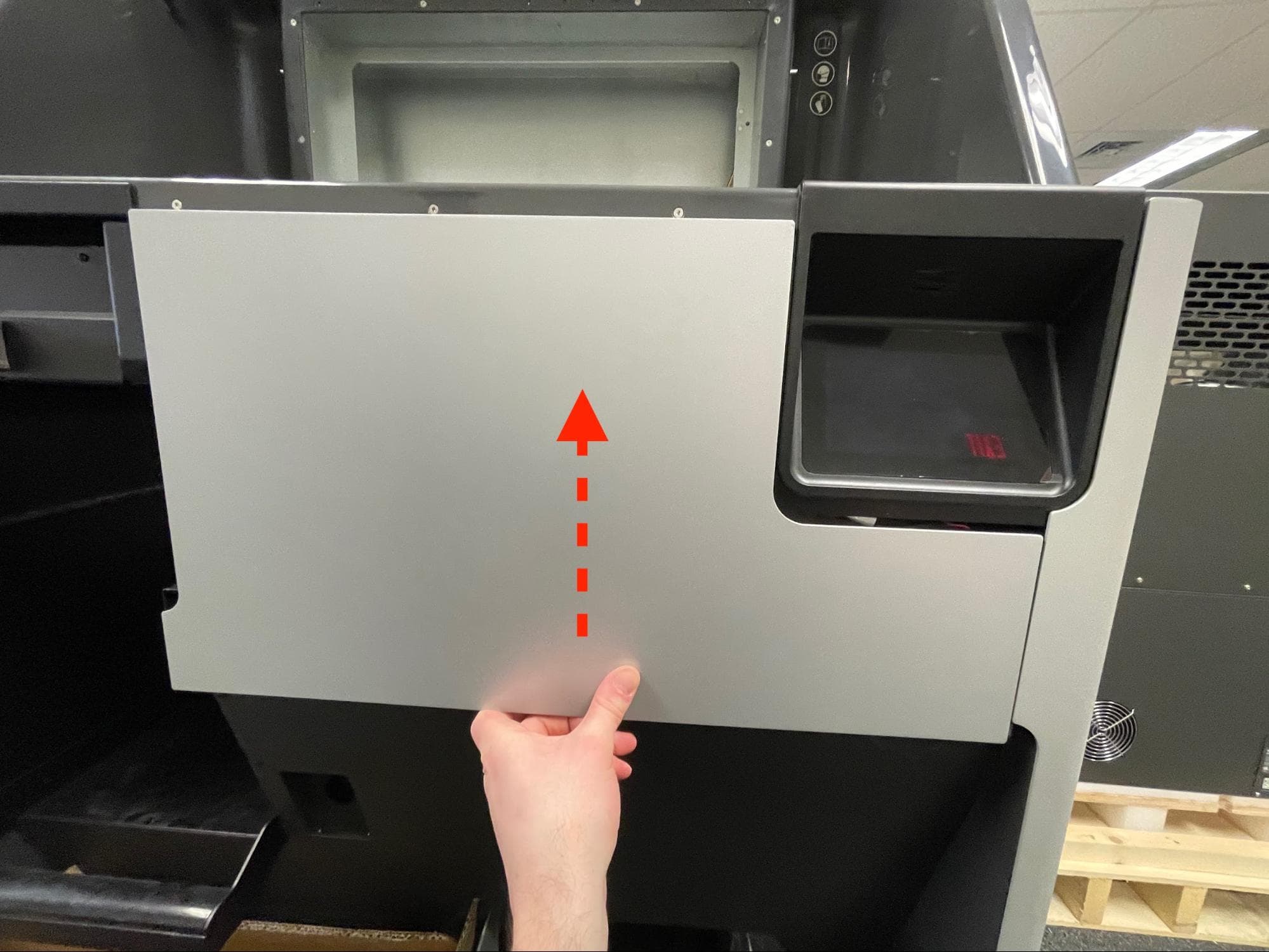
Slide the panel upwards until it locks into place. Note that the panel can still fall down if knocked or hit.

Replace the upper front enclosure panel

Step 3: Secure the upper front enclosure panel

Replace the upper front enclosure panel

Apply a small dab of Loctite 243 or equivalent threadlocker to each of the seven black 8.0 mm M4 button head screws that secure the upper front enclosure panel to the Fuse Sift. Thread one of the screws into each of the seven screw holes in the panel. Using a 2.5 mm hex driver, tighten the screws until snug.

Finalizing the repair

Overview: After installing the new sifter flange and gasket, power on the Fuse Sift and test its functions.

Step 1: Power on the Fuse Sift

Reconnect the Fuse Sift to its power source. Flip the power switch to the ON position.

Step 2: Test the sifter

Turn on the sifter using the Fuse Sift touchscreen. Check that the machine does not make any unexpected noises and does not leak powder through the sifter bellows. Contact Formlabs Support or your certified service provider to share the results of the procedure.