
Note:
Starting with PreForm 3.5, all parts printed on the Form 3/Form 3B have light-touch supports.

Supports are essential in SLA 3D printing, but they require removal and often leave marks behind. Our new Low Force Stereolithography (LFS) technology works in combination with a smaller laser spot size to allow the Form 3/Form 3B to print parts with a new support structure that is easier to remove. These redesigned supports provide all the additional stability of regular supports without the long post-processing time.
The term "light-touch supports" refers to the various and ongoing changes made to the support structure on all Form 3/3B printers. Each resin has a unique support geometry that is specifically tailored for that resin's application, such as light-touch supports for Castable Wax Resin.
Note:
Starting with PreForm 3.5, all parts printed on the Form 3/Form 3B have light-touch supports.
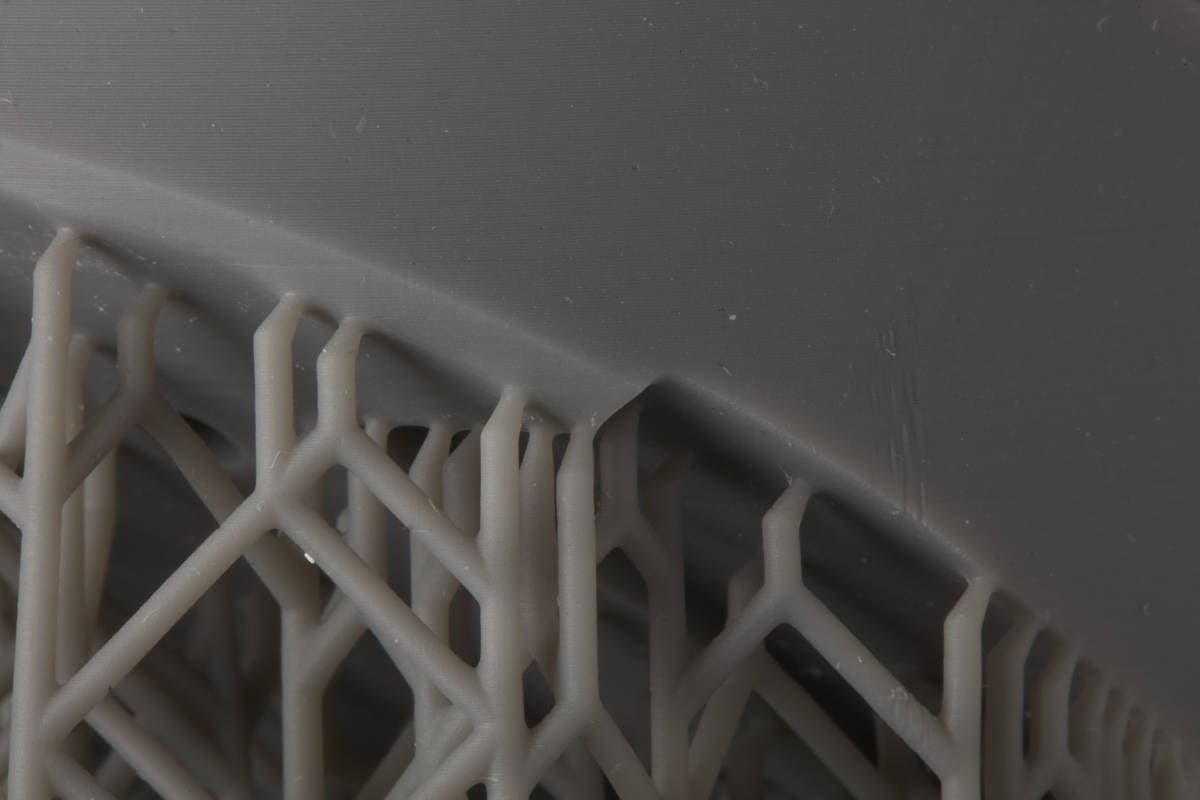
Left: Support structure for Grey Resin on the Form 2.
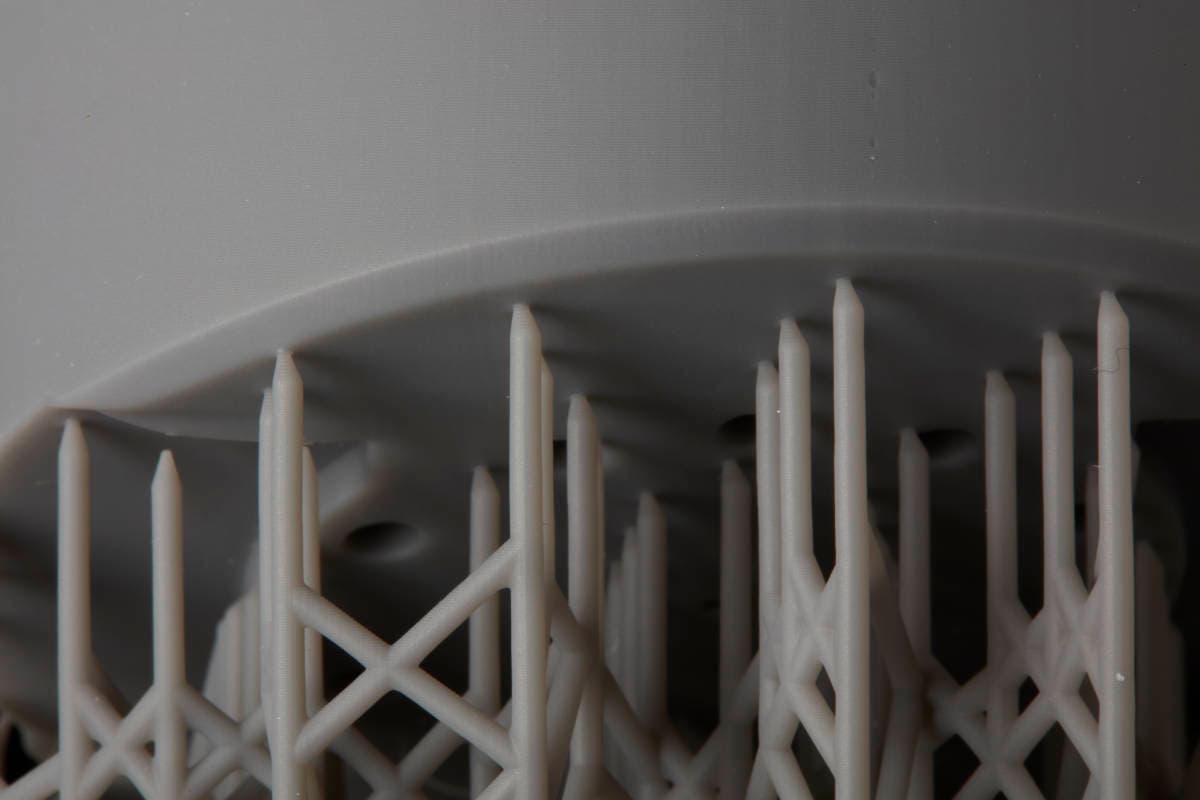
Right: Support structure for Grey Resin on the Form 3.
Redesigning the support structure
PreForm generates supports that are cross-linked together for increased strength and adhesion. On the Form 2, this cross-linking fills the entire space between the raft and the printed part, resulting in a uniformly rigid support structure. Because the support structure is equally strong everywhere, it can break unpredictably during removal.
The peel forces of the Form 3/Form 3B are significantly lower than those of the Form 2. As a result, the support structure does not need to be as robust at every point. The redesign takes full advantage of these lower forces to decrease both the touchpoint size and amount of cross-linking so that supports are easier to remove by hand. Any pressure you apply to the print as you tear the part away from the supports is now only distributed along the support touchpoints.
The following improvements have been made to the Form 3/Form 3B support structure:
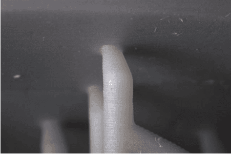
Left: Larger touchpoint size in Grey Resin on the Form 2.
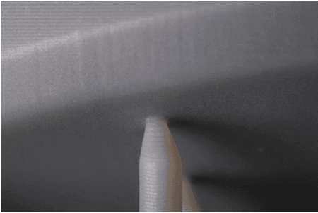
Right: Smaller touchpoint size in Grey Resin on the Form 3.
Removing supports comparison
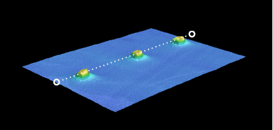
When tearing supports away by hand, the redesigned support structure on the Form 3/Form 3B leaves significantly less material behind.
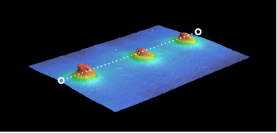
Left: Profilometer scan of material remains after part removal on the Form 2.
Right: Profilometer scan of material remains after part removal on the Form 3/Form 3B.