
Composite materials like glass fibers and carbon fiber get their high strength and light weight from the way the fiber strands are woven and laid out in the parts, offering unique opportunities to optimize designs based on the stresses engineers expect to affect the components. But working with these custom and non-standardized materials also presents a host of manufacturing challenges.
The University of Sheffield Advanced Manufacturing Research Centre (AMRC) Composites Centre conducts research using cutting edge methods to solve these challenges for high-value industries like aerospace, marine, and automotive.
One of the research projects in the facility explores filament winding, that is generally used to produce fuel pipes, tubes, vessels, and shafts for the aerospace and for automotive industries. Working with various materials that have different widths, the researchers had to adapt the system to process the fibers with the high accuracy required in the aerospace industry.
Read on to learn from Alexander Shaw, a composite automation technician working on the project, how the researchers designed and 3D printed different versions of the custom rollers and worked with the AMRC’s open access additive manufacturing station to manufacture the parts in days.
Watch the video story to look inside the Composites Centre and see how the researchers used the custom rollers for filament winding.
Shaw and the research team worked with the AMRC’s open access additive manufacturing station to manufacture the parts they needed. Read our case study to learn how open access to 3D printing can support hundreds of engineers across the site.
The Unique Challenges of Working With Composites
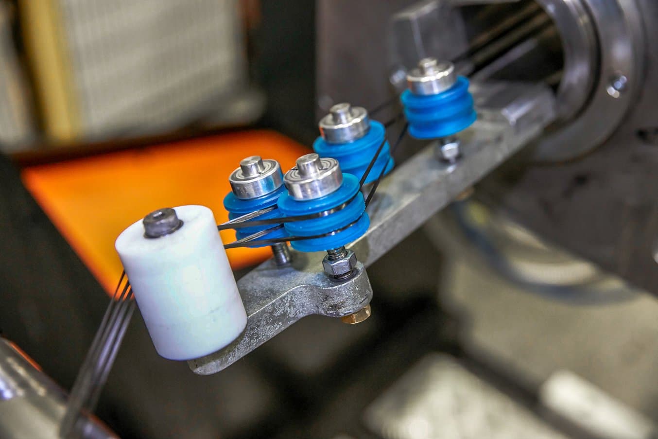
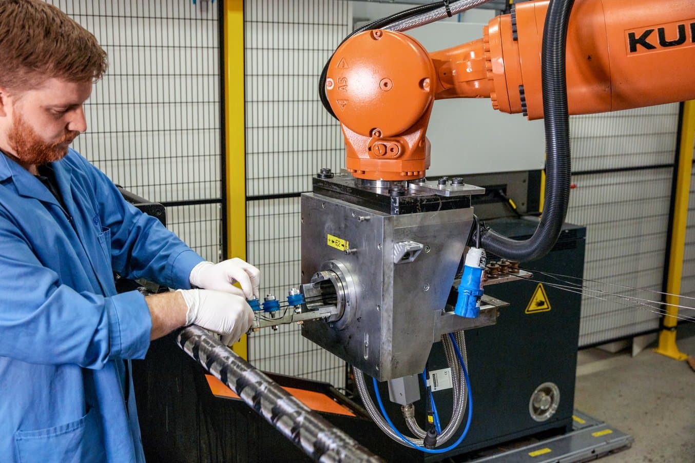
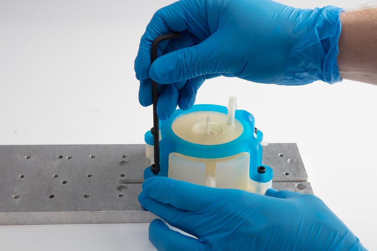
A filament winding machine works as follows: a spool of fiber goes through a resin bath and then runs through thin rollers to get from the creel at the back of the system to the payout head that is fixed to a 6-axis KUKA robot. The fiber strings then reach a metallic mandrel that is spun like a lathe. As the robot head moves, the fiber is laid down on top of the spinning mandrel.
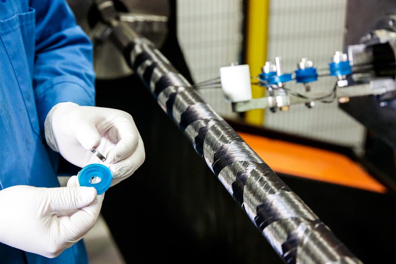
Different fibers can have different material widths or be slightly irregular, which can lead to issues with getting the fiber to process through the rollers. When the researcher switched to a different material that was slightly narrower than what they were using previously, the extra variation in the width required them to manufacture a roller that was slightly smaller than the part the came with the machine originally.
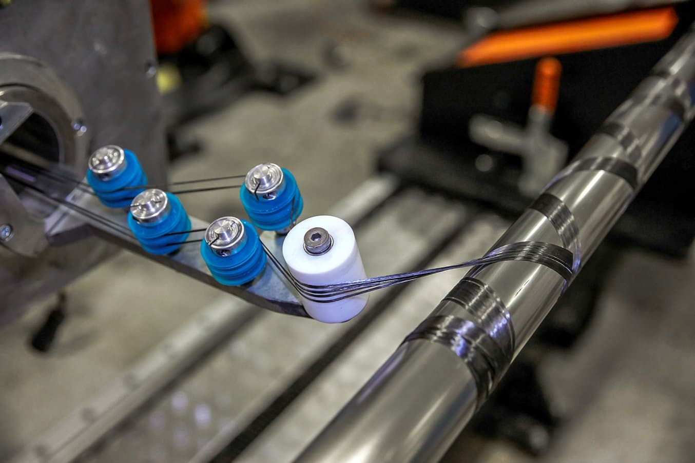
“If you've got a narrower toe width than the material you’re running through the rollers, you actually leave gaps in between the toes and it leaves a spread. If these gaps are bigger than about a millimeter, then the parts do not pass aerospace regulations,” Shaw said.
Producing the Parts with Additive Versus Subtractive Tools
To adapt the system to the new materials, Shaw looked at the standard rollers and designed three new versions, all with different diameters and widths depending on the material they were using. For example, for a quarter-inch-wide material, they printed rollers that had a middle section a quarter of an inch wide, and the outside sections of an eighth of an inch, so that when they put two strings together, side by side, there's no gap between the top and bottom creels.
The team needed the new rollers as soon as possible to continue with the project and decided that 3D printing would be their best option to produce the parts.
“Machining the new rollers would make the cost much higher and the lead times could potentially be over a week, whereas, with the Formlabs 3D printers, we're able to print something and have it in our hands the same day,” Shaw said.
Designing Jigs & Fixtures with 3D Printing
Download our white paper to learn how to reduce costs, shorten development time, and create more optimized production workflows with 3D printed jigs and fixtures.
Download White PaperUsing the In-House 3D Printing Station
“3D printing is something we have looked at previously. It's just how accessible it was to everybody. There were only three or four people who were trained on the machines before. The software and everything took a little bit more getting used to,” Shaw said.
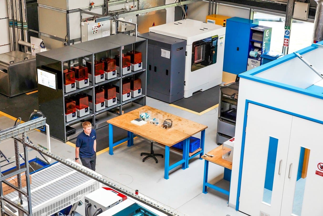
Shaw worked with the Design and Prototyping Group at the AMRC to produce the 3D printed parts. The group recently installed a new additive manufacturing station with a fleet of 12 Form 2 stereolithography (SLA) 3D printers that provides open access to 3D printing to all engineers across the site.
After receiving the new the printers, Mark Cocking, the polymer additive technical lead, reached out to everyone at the Composite Centre to ask if they were interested in receiving training.
”I think 90% of the people in the Composites Centre said, ‘yes, this is definitely something that we can use.’ It took just about 20-30 minutes show us the software and go through all the details. The software is so simple to use, it's a case of creating an STL and then dragging and dropping it into the software and it'll sort everything out for you. Now there are nearly a dozen people in our group that are have been trained on the Formlabs printers,” Shaw said.
Explore How a 3D Printing Station Supports Hundreds of Engineers at AMRC
Learn about the 3D printing station at the AMRC and see other applications like batch 3D printing of 500 high-precision drilling caps for drilling trials for Airbus, a temperature resistant sensor bracket for welding, and highly intricate brackets for a robot gripper in composites manufacturing.
Want to learn more about the printers and technology behind the AMRC’s 3D printing station? Explore Formlabs latest SLA 3D printers, the Form 3 and the large format Form 3L, and Formlabs collection of engineering resins for your own project, or request a free sample 3D printed part to see materials firsthand.