
Required Supplies:
Third-party:
- 2 .5 mm hex driver
- 3.0 mm hex driver
- Antistatic wrist band
- Safety glasses
- Nonreactive nitrile gloves

The motherboard (also referred to as the Frontal Lobe board or FoLoBo) controls primary system functionalities on Fuse 1 generation printers. A functioning motherboard contains several LEDs that indicate the status of the motherboard and other control boards.
Use this guide to check the motherboard LEDs on Fuse 1 generation printers.
Required Supplies:
Third-party:
Estimated time: 45–60 minutes
Danger:
Read and follow all safety instructions and warnings in the operator manual. Replacement with incorrect parts can lead to burns, shock, fire, or explosion. Dispose of all parts in accordance with local regulations.
Danger:
This procedure involves operating a Fuse 1 generation printer with the top panel removed. Do not touch any electrical components on the printer while in this state, they should only be observed from a reasonable distance.
Preparing the workspace
Overview: Prepare the printer and a dust-free workspace for checking the motherboard LEDs.
Notice:
Fuse 1 generation printers contain sensitive electronic components. Ground yourself before touching any electronics in the printer by using a grounding strap or touching a grounded piece of metal.
Step 1: Prepare the workspace
Clear a workspace around your printer. Ensure that the workspace is well-ventilated and free of dust.
Step 2: Unplug the printer
Disconnect the power cable before continuing with maintenance. Do not perform maintenance on the printer while it is connected to power. Wait five minutes after disconnecting the printer from power before proceeding.
Danger:
Performing maintenance on the printer while it is plugged in increases the risk of electric shock. Never remove the back panel of the printer while the printer is plugged in.
Removing the top enclosure panel
Overview: Remove the top enclosure panel to access the interior of the printer.
Step 1: Unscrew the top panel screws
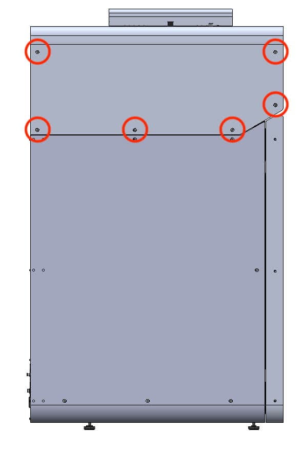
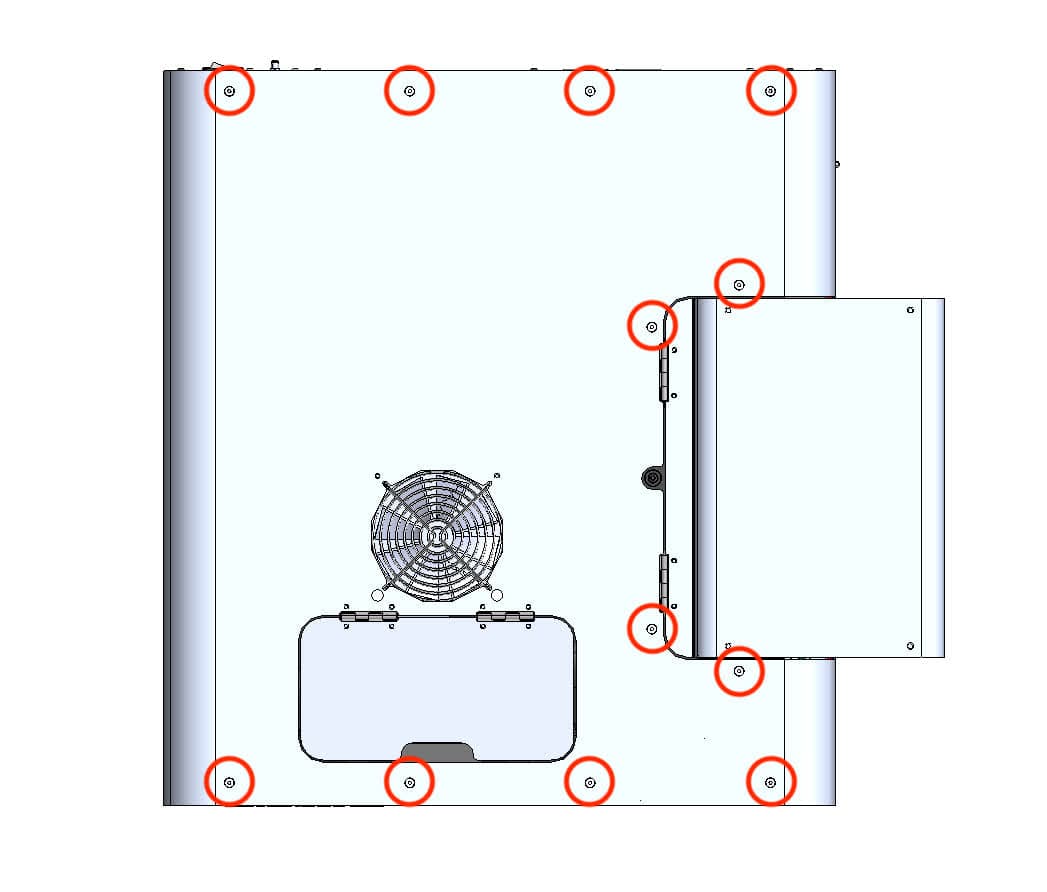
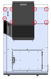
Using a 2.5 mm hex driver, remove the 26 top panel screws securing the top panel to the printer. Set the screws aside.
Step 2: Remove the top panel from the printer
Lift the top panel off of the printer by grabbing the IR sensor door and the rear-most edge. Set the top panel aside.
Removing the upper cooling shroud
Overview: Remove the upper cooling shroud to access the interior of the printer.
Notice:
The Fuse 1 contains sensitive electronic components. Ground yourself before touching any electronics in the printer by using a grounding strap or touching a grounded piece of metal.
Step 1: Remove the IR sensor
Grip the IR sensor cap and pull. The IR sensor is held in place with magnets and comes out with little force.
Step 2: Unplug the IR sensor ethernet cable
Unplug the IR sensor ethernet cable. Feed the ethernet cable through the plastic shroud so that it drops into the printer. Set the IR sensor aside on a flat surface with the sensor window facing up. If your printer does not have a nitrogen supply, skip ahead to Step 8: Unscrew the upper cooling shroud.
Step 3: Disconnect the N2 sensor and valve (Fuse 1+ 30W only)
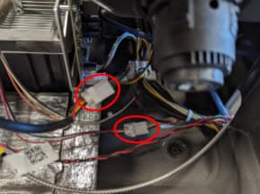
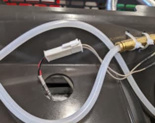
Disconnect the N2 sensor and valve from the cable labeled CBL-109131-00. Feed the cable through the plastic shroud so that it drops into the printer.
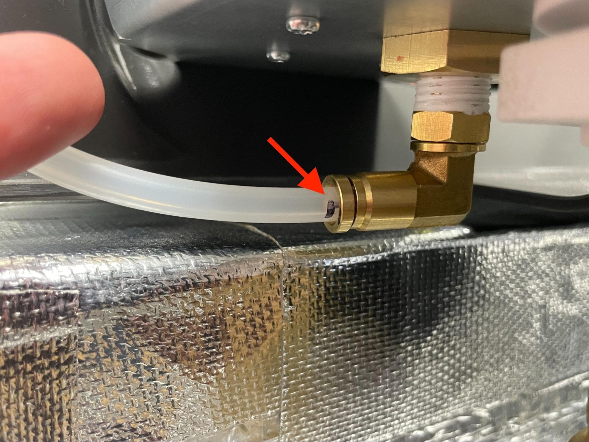
Using a permanent marker, mark the N2 downstream tube to indicate its install depth while connected to the N2 T-splitter.
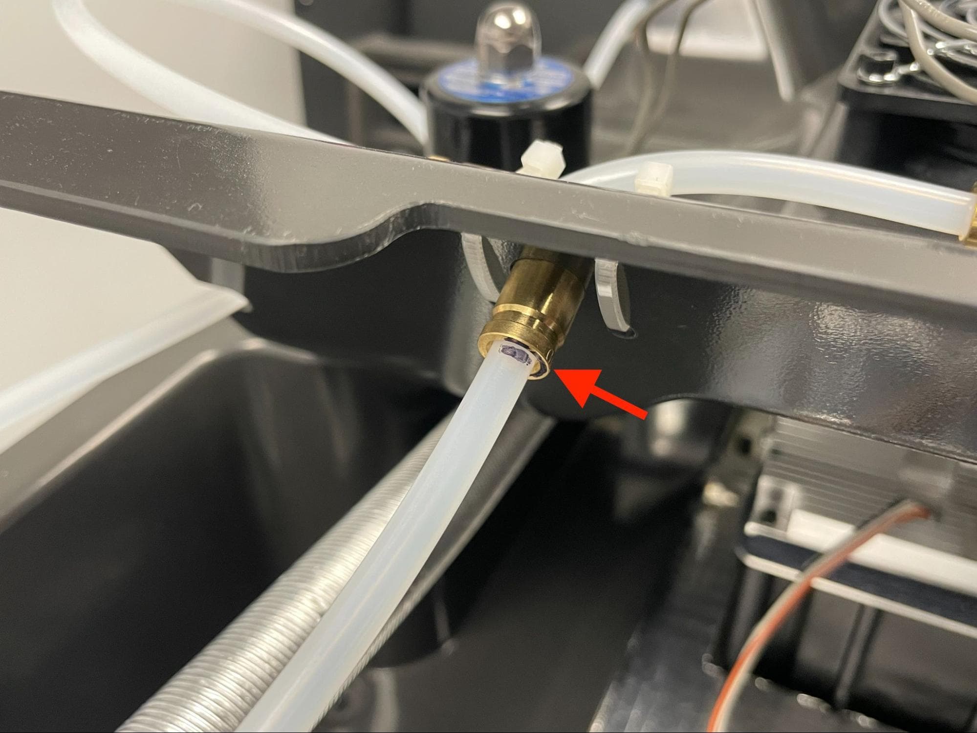
While pulling on the N2 downstream tube, push the brass ring down to decouple the tube from the N2 T-splitter.
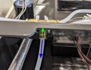
Using a permanent marker, mark the N2 intake tube to indicate its install depth while connected to the N2 intake plenum.
While pulling on the N2 intake tube, push the brass ring down to decouple the tube from the N2 intake plenum.
Step 8: Unscrew the upper cooling shroud
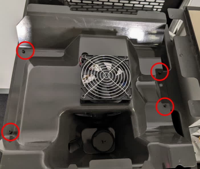
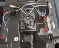
Using a 3.0 mm hex driver, remove the four screws securing the upper cooling shroud to the printer. Newer units also contain four washers. Set the screws and washers, if present, aside.
Notice:
Do not remove the upper cooling shroud without disconnecting the attached cables.
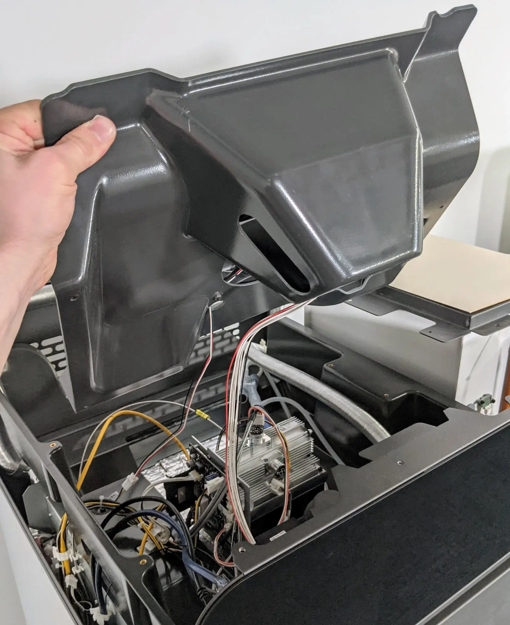
Gently lift up but do not separate the front edge of the plastic shroud from the top of the printer to access the attached cables. Take care not to pull on the cables, as this may damage them.
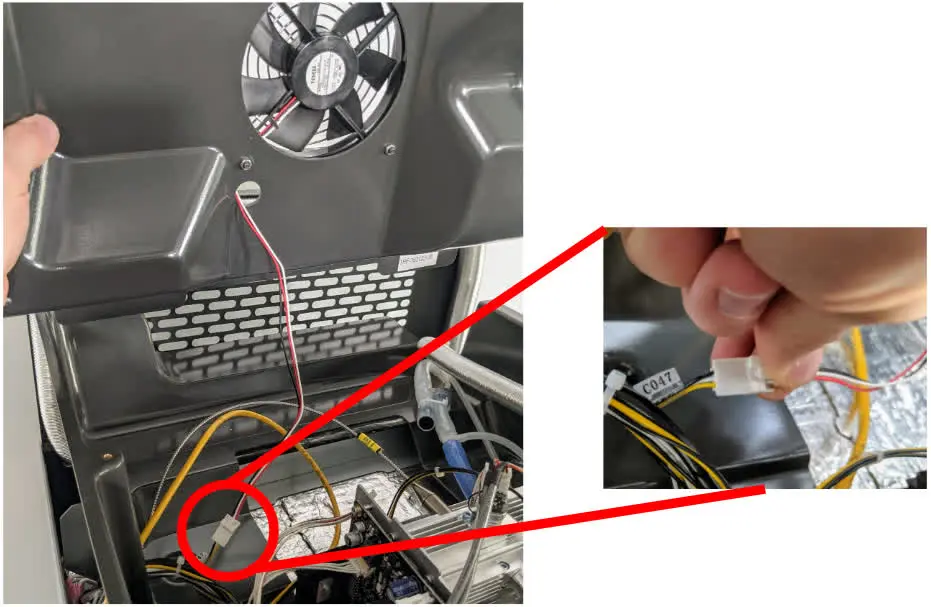
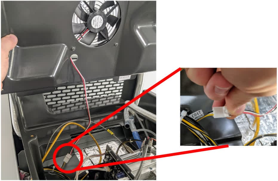
Disconnect the fan cable labeled CO47 by squeezing the plastic latch and gently pulling the connectors away from each other. Do not pull on the wires.
Tip:
Formlabs recommends having one person hold the upper cooling shroud while another person unplugs the cables.
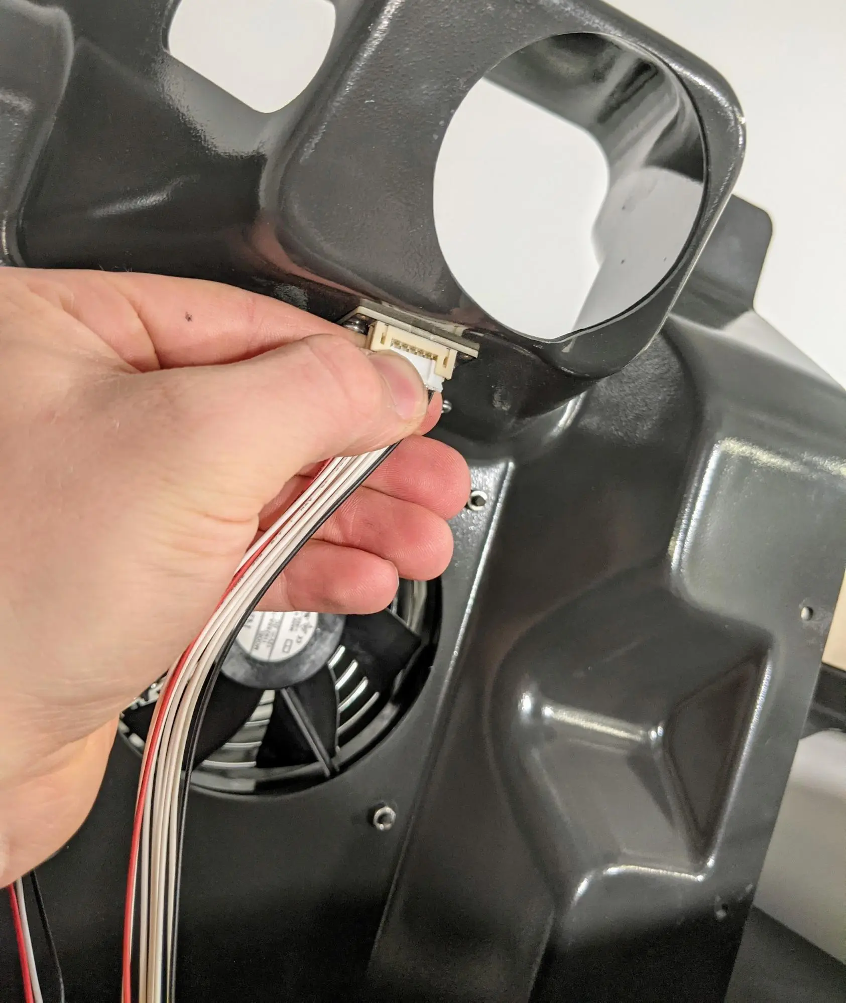
Grip the plastic connector on the RFID reader cable and pull directly away from the upper cooling shroud. Do not pull on the wires.
Step 12: Remove the upper cooling shroud
Once all the cables are disconnected, lift the upper cooling shroud away from the machine. Set the upper cooling shroud aside.
Checking the motherboard LEDs
Overview: With the printer turned on, check the motherboard LEDs
Step 1: Power on the printer
Connect the power cable to the printer and the power supply. Power on the printer.
Danger:
This procedure involves operating a Fuse 1 generation printer with the top panel removed. Do not touch any electrical components on the printer while in this state, they should only be observed from a reasonable distance.
Step 2: Locate the motherboard
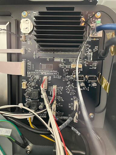
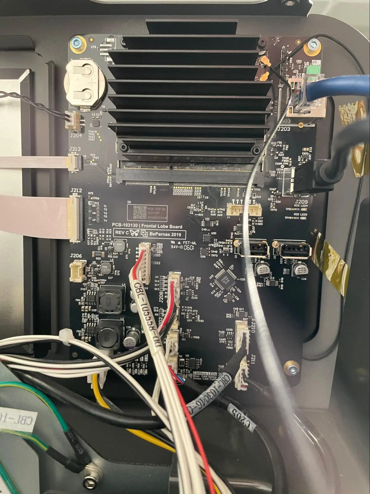
Locate the motherboard (also known as a Frontal Lobe board or FoLoBo) on the side of the printer opposite the hopper. It is mounted to the back of the front display panel, and has visible USB and Ethernet connections.
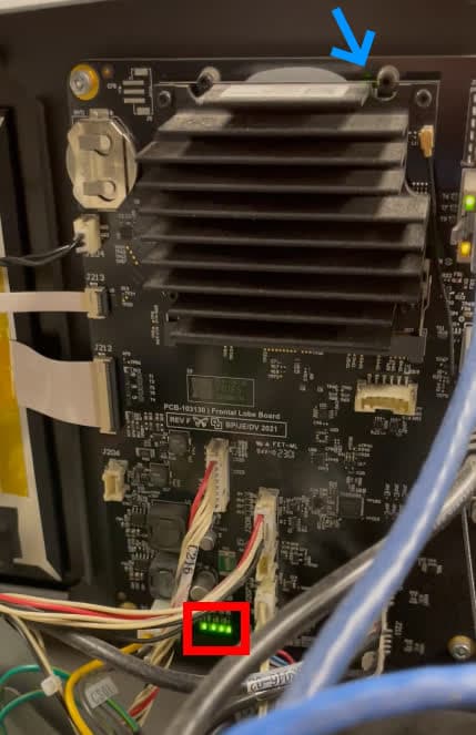
The motherboard has two sets of indicator LEDs: one blinking LED behind the SOM at the top of the motherboard and four green LEDs at the bottom. From left to right, the bottom LEDs are labelled:
Inspect the motherboard for illuminated LEDs. Note which LEDs are illuminated, blinking, or off. Take a video of the motherboard LEDs for reference to give to Formlabs Support or your certified service provider.
Step 4: Unplug the printer
Disconnect the power cable before continuing with maintenance. Do not perform maintenance on the printer while it is connected to power. Wait five minutes after disconnecting the printer from power before proceeding.
Reinstalling the upper cooling shroud
Overview: Reinstall and secure the upper cooling shroud.
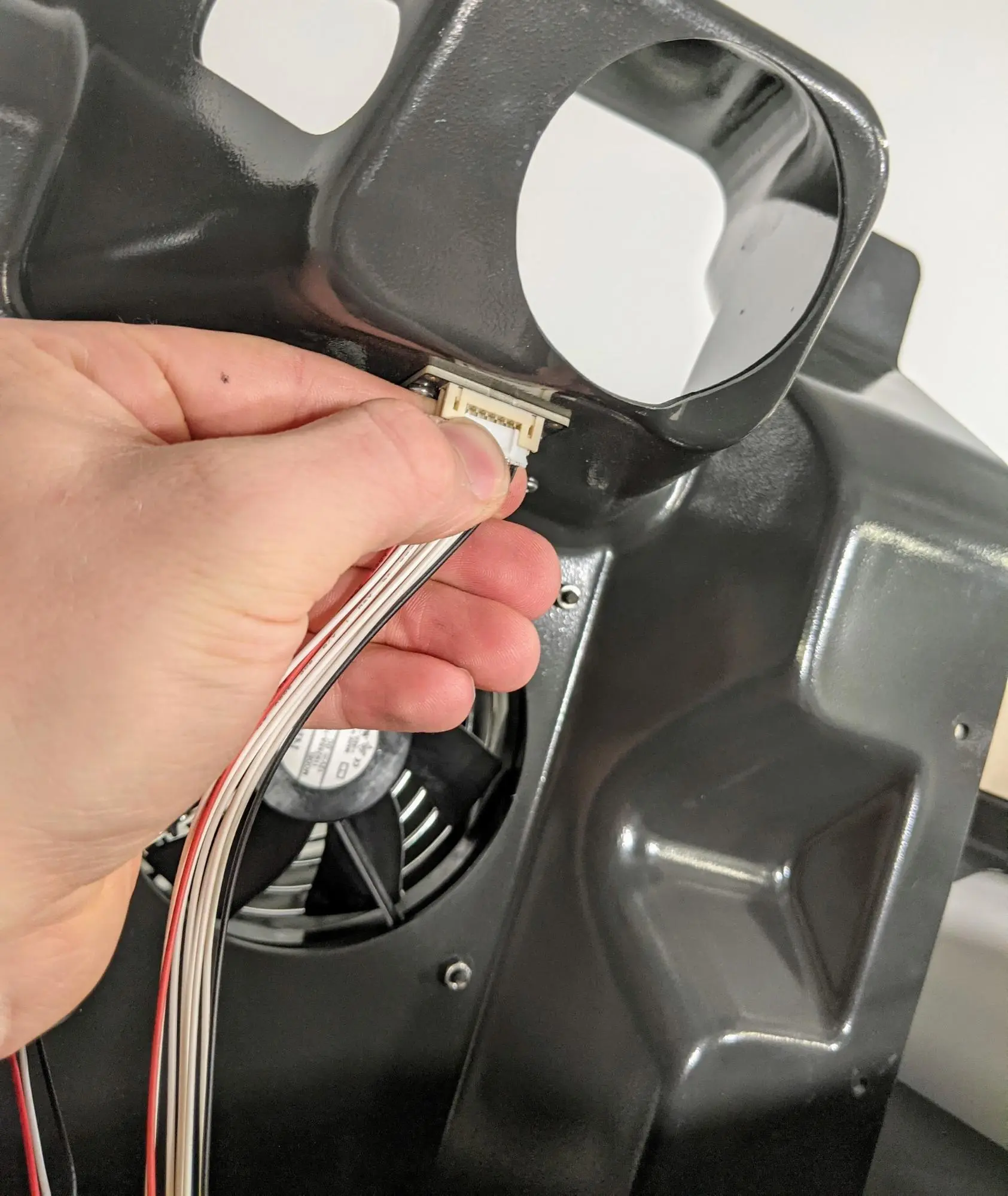
With one person holding the upper cooling shroud above the printer, reconnect the RFID reader cable into the white connector. The cable will only enter the connector in the correct orientation. Be careful not to bend the pins in the connector. Do not pull on the wires.
Step 2: Reconnect the fan cable to the upper cooling shroud
With one person holding the upper cooling shroud above the printer, reconnect the cooling fan cable into the socket labeled C047. The cable will only enter the connector in the correct orientation. Be careful not to bend the pins in the connector.
Step 3: Align the cooling shroud above the printer
Hold the upper cooling shroud by the front edge and align it above the printer so that you can access the cables covered by the shroud. Feed the IR sensor ethernet cable through the cutout in the top shroud.
Thread one screw and washer, if present, into each of the four screw holes in the upper cooling shroud. Using a 3.0 mm hex driver, tighten the screws until finger tight. If your printer does not have a nitrogen supply, skip to Step 9: Inspect the IR sensor lens.
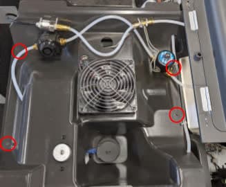
Tuck the N2 tube connected to the T-splitter and N2 valve under the hopper shroud flange.
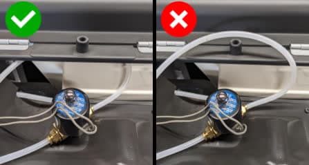
Step 6: Reconnect the N2 sensor and valve (Fuse 1+ 30W only)
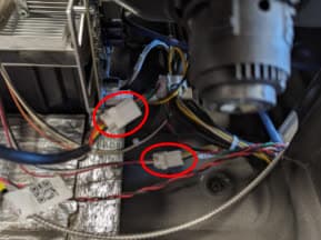
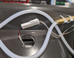
Reconnect the N2 sensor to the cable labeled CBL-109131-00. Feed the cable back through the cutout in the upper cooling shroud, then reconnect the N2 valve to the cable.
Step 7: Insert the N2 downstream tube into the T-splitter (Fuse 1+ 30W only)
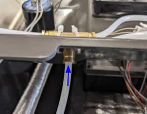
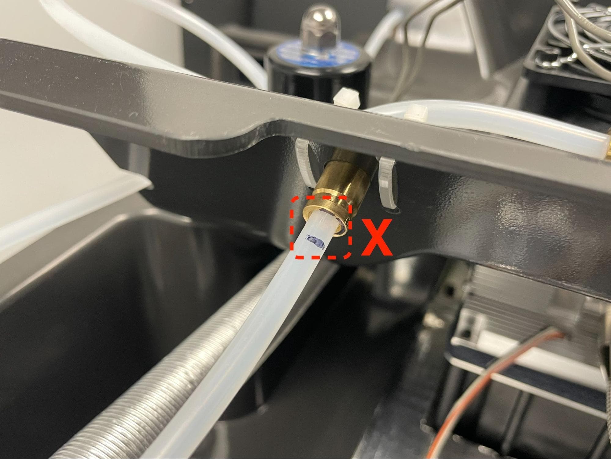
Insert the N2 downstream tube into the middle fitting of the brass N2 T-splitter. Ensure the depth indicator mark aligns with the fitting’s release ring.
Step 8: Insert the N2 intake tube into the intake plenum (Fuse 1+ 30W only)
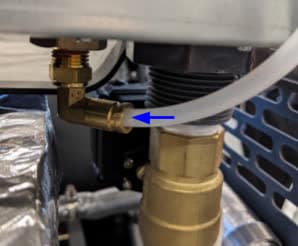
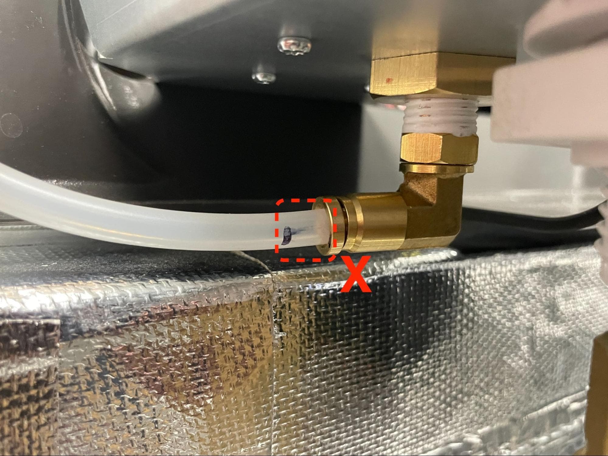
Insert the N2 intake tube into the N2 intake plenum’s brass fitting. Ensure the depth indicator mark aligns with the fitting’s release ring.
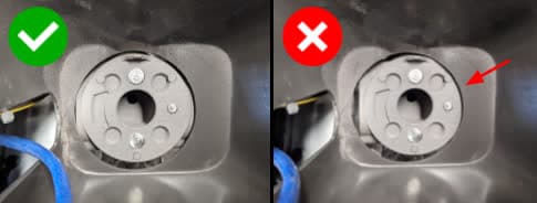
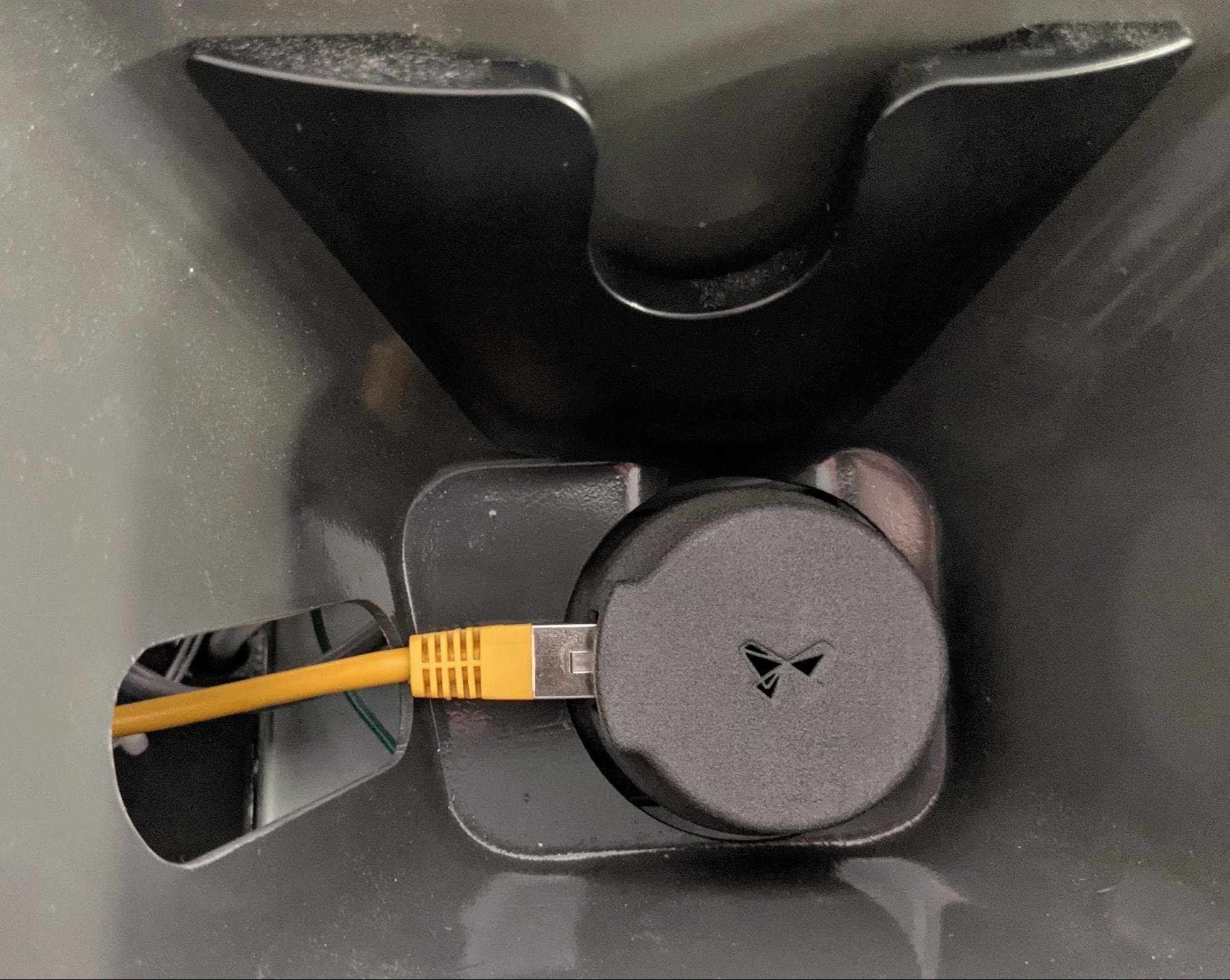
Inspect the IR sensor lens for debris. Clean the IR sensor lens with ethanol and PEC*PAD if needed. Check the lens to ensure that there are no streaks and that the contamination has been fully removed.
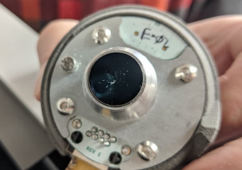
Reconnect the ethernet cable to the IR sensor, then push the IR sensor cap into the mount.
Reinstalling the top enclosure panel
Overview: After performing any other maintenance procedures, reinstall and secure the top enclosure panel.
Step 1: Align the top enclosure panel with the printer
Lift the top enclosure panel by grabbing the IR sensor door and the rear-most edge, then align it with the top of the printer.
Step 2: Secure the upper enclosure panel
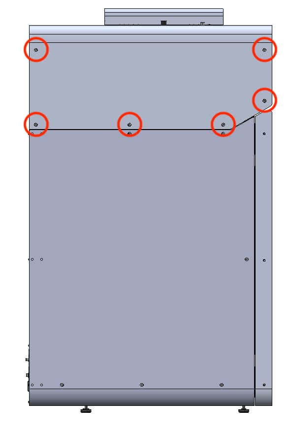
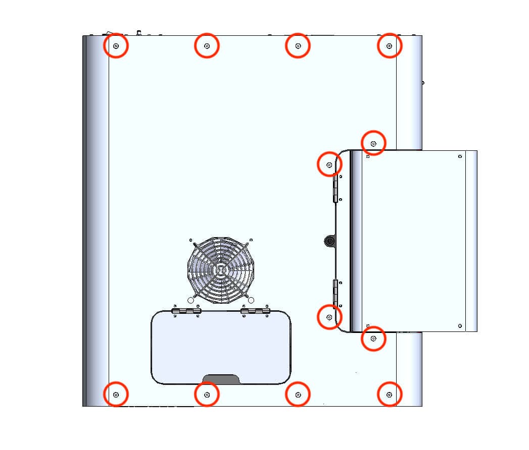
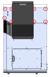
Thread the six 6 mm screws into the screw holes on the buffer side of the printer, the twelve 6 mm screws into the top of the printer, and the eight 6 mm screws into the hopper side of the printer. Using a 2.5 mm hex driver, tighten the screws until snug.
Finalizing the repair
Overview: After checking the motherboard LEDs, power on the printer and perform final checks.
Step 1: Power on the printer
Close the printer cover and connect the power cable to the printer and the power supply. The printer initializes. Contact Formlabs Support or your certified service provider to share the results of the procedure.