LIVRE BLANC
Formlabs Logo

Design specifications for 3D models (Form 2)

Design specifications for 3D models (Form 2)

Une bonne impression 3D commence par un modèle bien conçu. Suivez bien ces bonnes pratiques pour optimiser vos modèles et réduire les erreurs d’impression.

Note:

The guidelines below were developed using Formlabs Clear Resin printing at 100 microns on the Form 2. You may experience slight variations with other Formlabs resins, different Formlabs printers, and various layer thicknesses.

Épaisseur minimale des parois avec supports

Recommended: 0.4 mm/400 microns

A supported wall is one that is connected to other walls on two or more sides. A supported wall with a thickness of 0.4 mm or less may warp due to the peel forces exerted on the part during the peel process.

Note: Washing thin walls

Take care when washing parts with thin walls, which may absorb solvents such as IPA during the washing process. Spending an extended duration in a washing solution can cause deformation of the part, so minimize how long the part is immersed in IPA to limit this effect.

Épaisseur minimale des parois sans supports

Recommended: 0.4 mm/400 microns

An unsupported wall is one that is connected to other walls on fewer than two sides. An unsupported wall with a thickness of 0.4 mm or less may warp or detach from the model during printing.

Note: Washing thin walls

Take care when washing parts with thin walls, which may absorb solvents such as IPA during the washing process. Spending an extended duration in a washing solution can cause deformation of the part, so minimize how long the part is immersed in IPA to limit this effect.

Longueur maximale d’une partie en surplomb non soutenue

Recommended: 3.0 mm/3000 microns

An overhang refers to a part of the model that extends parallel to the build platform. Printing such features without support is discouraged, as layers that cannot maintain their structure often warp or detach. Horizontal overhangs beyond 3 mm do not completely form and become increasingly deformed as the length of the overhang increases. Change the orientation of the model, or click Supports and select Internal Supports in PreForm to ensure overhangs are supported.

Angle minimum pour parties en surplomb non soutenues

Recommended: 19° from level

(35 mm long × 10 mm wide × 3 mm thick)
An overhang set at an angle of 19 degrees or less can break off the model during the peel process. Refer to the support article Moving and rotating a model in PreForm to rotate flat surfaces to be more self-supporting.

Portée horizontale maximale des supports

Recommended: 21 mm/21,000 microns

(5 mm width × 3 mm thick)
Span is the distance between two supports. Printing horizontal spans is discouraged, but certain geometries may print successfully. For a 5 mm wide and 3 mm thick beam, spans longer than 21 mm are more likely to fail. Wider beams must be kept shorter to avoid print failures.

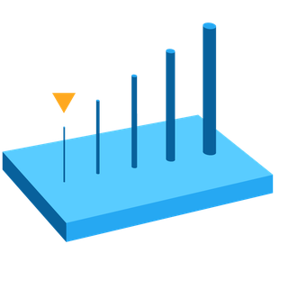
Diamètre minimum des fils verticaux

Recommended for a 7 mm-tall wire: 0.4 mm/400 micron diameter
Recommended for a 30 mm-tall wire: 1.5 mm/1500 micron diameter

A wire is a feature whose length is at least two times greater than its width. A wire with a 0.4 mm width can be up to 7 mm tall before it begins to deform. Similarly, a wire with a 1.5 mm width can be up to 30 mm tall before it begins to deform.

REMARQUE : LAVER LES PETITS FILS, BÂTONNETS ET AUTRES CABLES

Il faut faire très attention en lavant les éléments filaires de faible diamètre, car ils sont fragilisés par l’alcool isopropylique et peuvent facilement être endommagés. Réduisez le temps d’immersion dans l’alcool isopropylique pour limiter cet effet.

Épaisseur minimale des détails en relief

Recommended: 0.1 mm/100 microns

Embossed details are shallow raised features on the surface of a model like text. Details less than 0.1 mm thick and 0.1 mm tall may not be visible on the completed print.

Épaisseur minimale des détails gravés

Recommended: 0.4 mm/400 microns

Engraved details are imprinted or recessed features on the surface of a model. Details recessed less than 0.4 mm deep or 0.4 mm wide may fuse with the rest of the model during printing.

Jeu minimum

Recommended: 0.5 mm/500 microns

Clearance is the distance between two parts of a model (e.g., the distance between a pair of gears). Parts may fuse if clearance is less than 0.5 mm.

Diamètre minimum des alésages

Recommended: 0.8 mm/800 microns

Holes with a diameter of less than 0.8 mm in the X-, Y-, and Z-axes may close during printing.

Diamètre minimal des trous de drainage

Recommended: 3.5 mm/3500 micron diameter

Drain holes are recommended for resin to escape in models that are a fully enclosed cavity (like a hollow sphere or hollow cylinder printed directly on the build platform). Without drain holes of at least 3.5 mm in diameter, the part may trap resin or air and lead to a cupping blowout failure.