

Glossaire produit (Form 2)
Glossaire produit (Form 2)
Utilisez ce glossaire et ce modèle 3D comme guide pour explorer les composants internes de la Form 2. L'imprimante interactive et les définitions peuvent également être utiles pour diagnostiquer les problèmes d'impression.
Avant de consulter les notations du modèle 3D, lancez l’animation Démontage (cliquez sur Pose statique si l’animation n’est pas déjà en cours). Appuyez à tout moment sur le bouton Pause. Faites glisser le curseur en bas de la fenêtre pour passer à n’importe quel point. Les notations sur le modèle fonctionnent mieux à la fin de l’animation.
Composants externes
| Article | Description | Image |
| Coque | Cette couverture métallique protège les composants internes de l’imprimante. Elle est constituée de deux parties. | Pieds réglables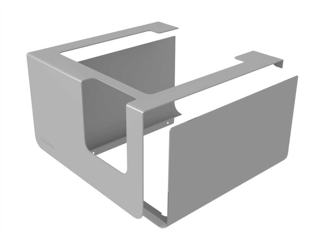 |
| Chaque coin de l’imprimante est soutenu par un pied en caoutchouc vissé dans le fond de la machine. | Lorsque l’écran tactile vous y invite, utilisez l’outil de mise à niveau pour relever ou abaisser chaque pied afin de vous assurer que l’imprimante est suffisamment de niveau. |  |
Ensemble d’affichage
| Élément | Description | Image |
| Écran tactile | L’écran LCD affiche les informations d’impression, les paramètres et les messages d’erreur. Il constitue l’interface utilisateur de la Form 2. |  |
| Carte de circuits imprimés d’affichage | Cette carte de circuits imprimés, séparée de la carte mère principale, contrôle l’écran tactile. | 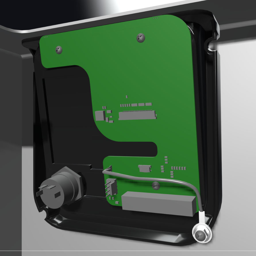 |
| Câble en nappe | Ce câble relie l'écran tactile à la carte mère. | 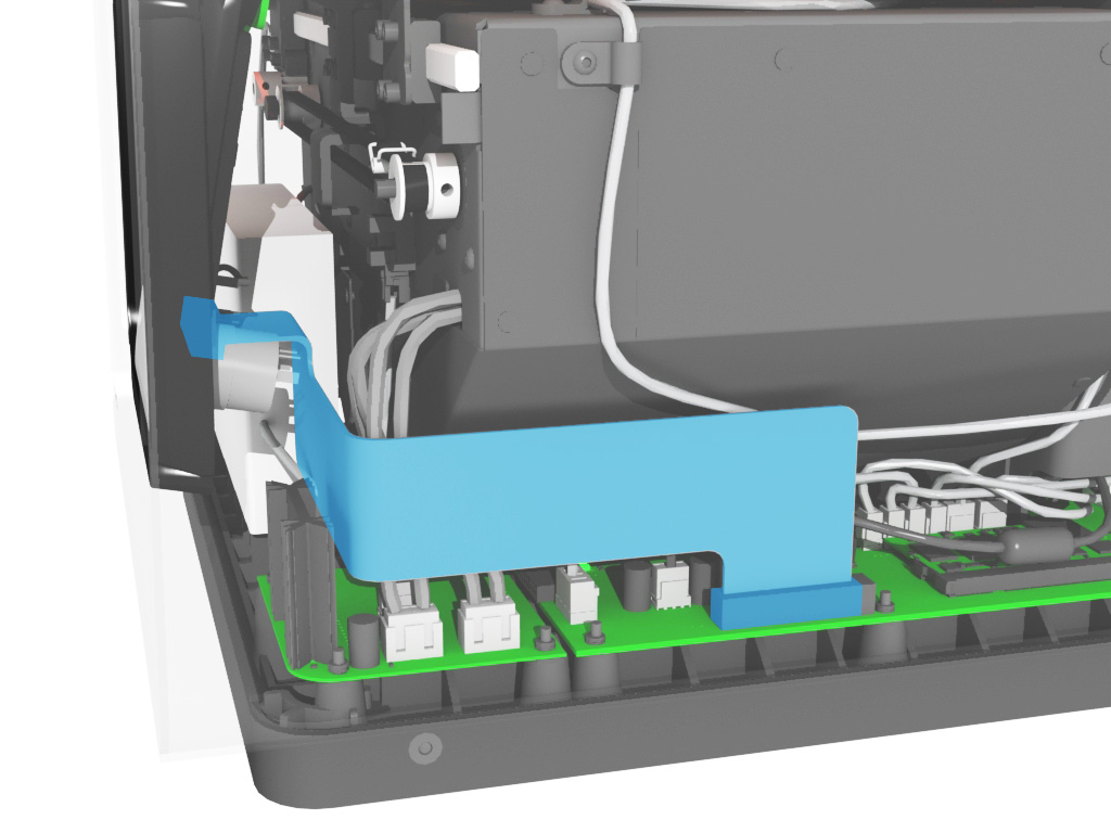 |
| Bouton-poussoir | Le bouton démarre et met en pause les impressions lorsque l’écran tactile le demande. Vous pouvez mettre en pause ou redémarrer l’imprimante en maintenant ce bouton appuyé. | 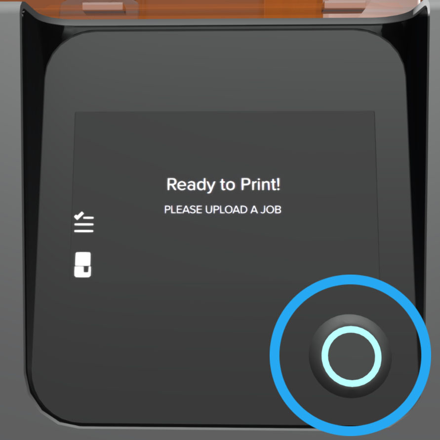 |
Couvercle orange
| Article | Description | Image |
| Couvercle orange | Le couvercle est moulé par injection à partir de polycarbonate à haute résistance aux chocs. Elle est teintée en orange pour bloquer l’exposition au laser et protéger la résine de la polymérisation due à la lumière UV ambiante. |  |
| Aimants de verrouillage | Les aimants de verrouillage maintiennent le couvercle orange en place. | 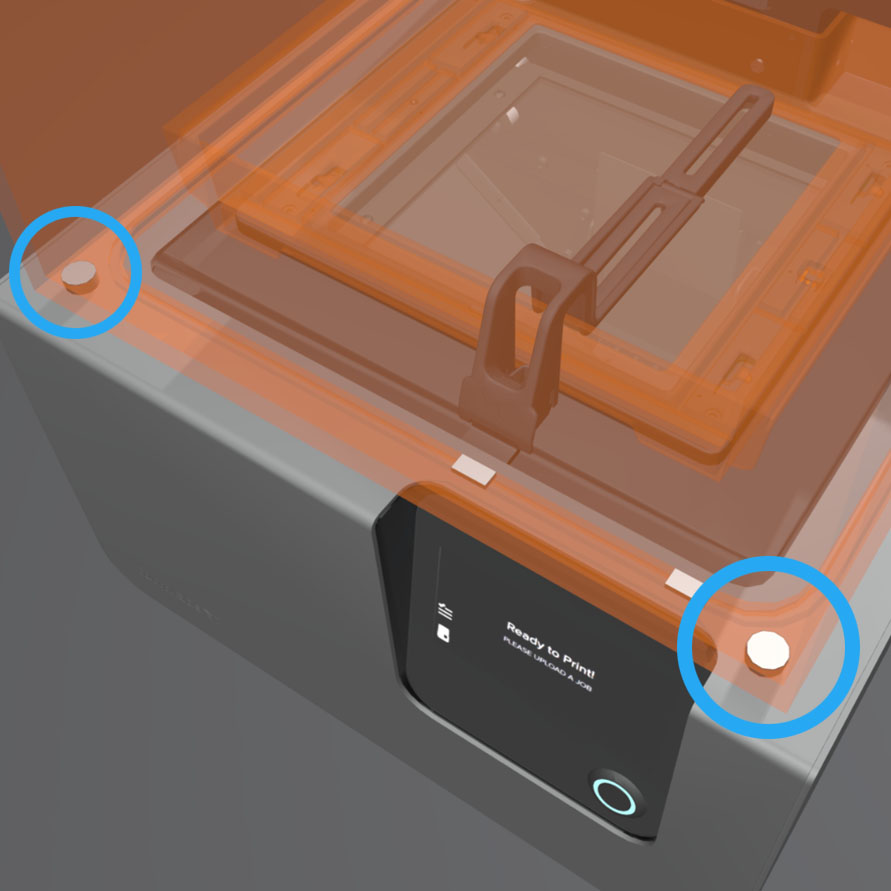 |
| Aimants de verrouillage | Le capteur de verrouillage détecte ces aimants pour déterminer quand le couvercle est fermé. Ce mécanisme de sécurité déclenche le message Cover Open (Couvercle ouvert) sur l’écran tactile et désactive le laser lorsque le couvercle est ouvert. | 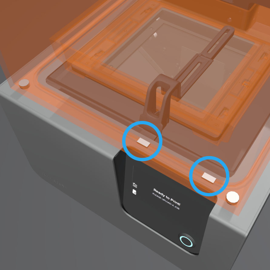 |
Cartouche
| Article | Description | Image |
| Cartouche | Ce récipient contient la résine avant de la distribuer dans le bac à résine.Secouez la cartouche périodiquement pour que la résine reste bien mélangée. |  |
| Capuchon d’aération | Le couvercle situé en haut de la cartouche permet l’échange d’air, de sorte que la résine se distribue correctement. Il faut appuyer sur le clapet d'entrée d'air pour qu’il s’ouvre avant de commencer une impression. | 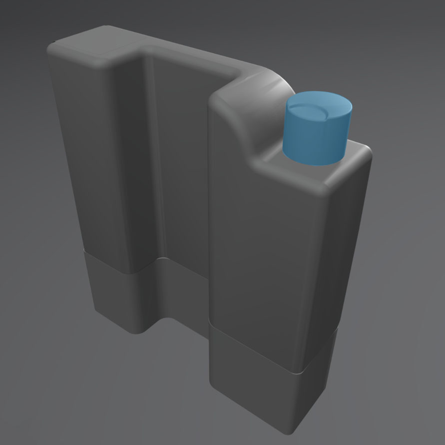 |
| Puce d’identification de la cartouche | Une puce EEPROM (mémoire morte programmable effaçable électriquement) est fixée à la jupe de la cartouche et est programmée avec le type de résine. Il communique avec l’imprimante via les contacts à ressort se trouvant sur la base de la cartouche. |  |
| Valve de distribution | Ce joint flexible régule la distribution de la résine. La résine coule lorsque le bras de distribution de la cartouche appuie sur la valve pour l'ouvrir. |  |
Support de la cartouche
| Article | Description | Image |
| Doigts de détection de la cartouche | Deux contacts électriques composent les doigts de détection situés sur la base de la cartouche. Le contact physique établit une connexion électrique avec la puce d’identification de la cartouche pour détecter la cartouche. |  |
| Bras de distribution de la cartouche | Ce crochet en plastique appuie sur la valve de distribution pour distribuer la résine de la cartouche dans le bac à résine. | 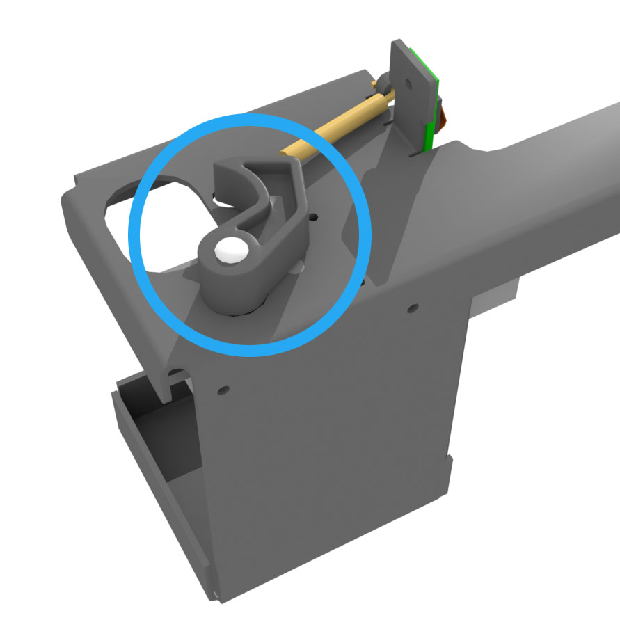 |
Axe Z
| Item | Description | Image |
| Z-tower | This vertical tower at the back of the printer provides support for many parts of the Form 2. The build platform is raised and lowered along the Z-axis, inside the tower. The Z-tower also encloses the resin cartridge and the mechanisms for dispensing the resin into the tank. | 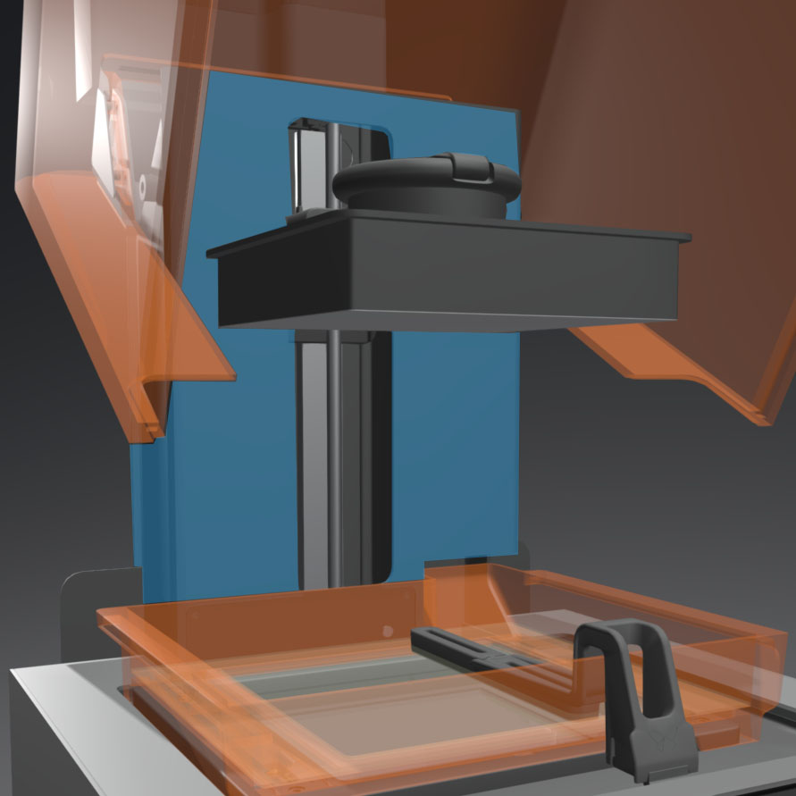 |
| Lead screw | The lead screw controls the vertical motion of the build platform carriage. | 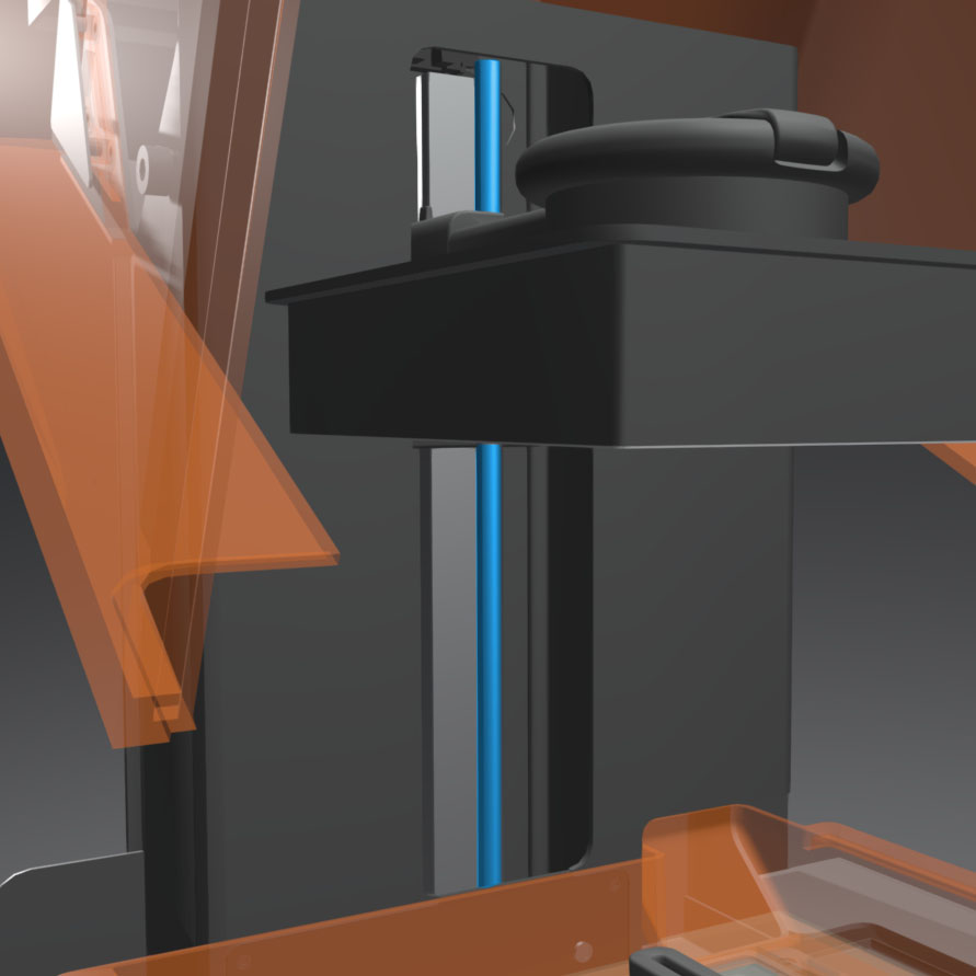 |
| Z-axis limit switch | This optical sensor tells the motor driver when the build platform has reached the top of the tower. | 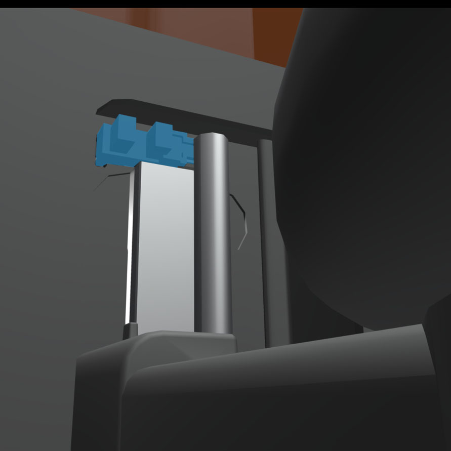 |
Plateforme de fabrication
| Item | Description | Image |
| Build platform | The aluminum base provides a surface for prints to attach to. |  |
| Cam handle | This lever is part of the locking mechanism that secures the build platform. Raise the cam handle before inserting the build platform, and lower the cam handle to lock the platform into place. | 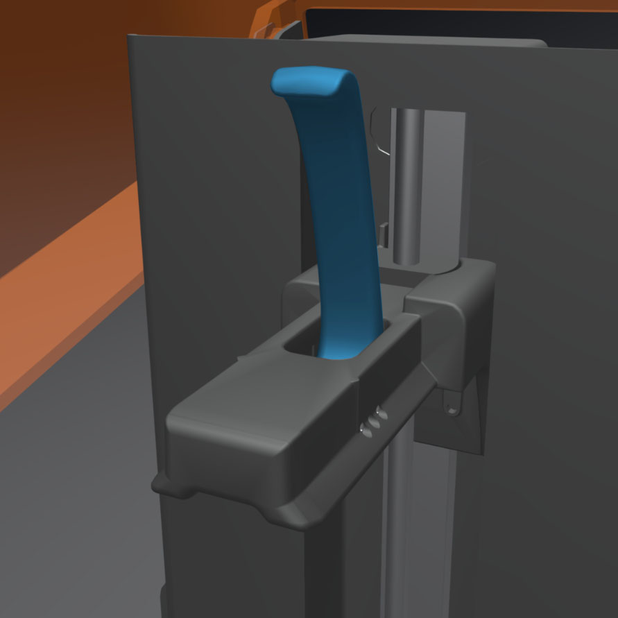 |
| Build platform carriage | The carriage is the metal arm that the build platform slides onto. | 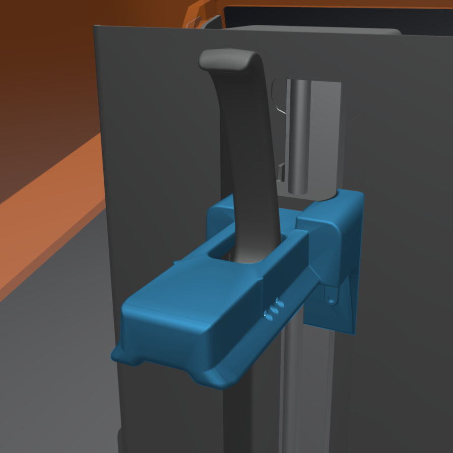 |
| Cam lock spring | The spring mechanism inside the build platform carriage allows the cam handle to move up and down. Il assure également le verrouillage et le déverrouillage mécanique de la plateforme de fabrication. |  |
| Cam lock set screws (x3) | These three screws are used for adjusting the tension in the cam lock. We advise contacting Support before adjusting these screws, as improper adjustment can lead to damage to the machine. | 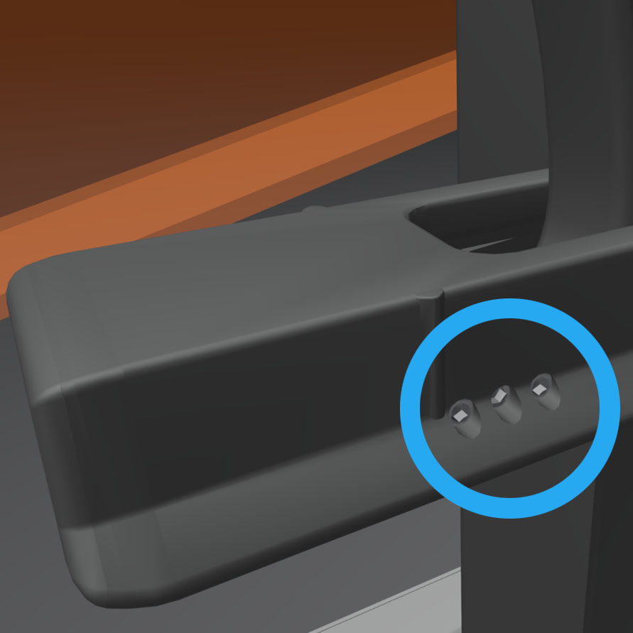 |
Bac à résine
| Item | Description | Image |
| Resin tank | The polycarbonate resin tank is the primary container for holding resin after it is dispensed from the cartridge. Resin is cured onto the build platform when the laser passes through the tank's acrylic plastic window. Only use approved chemicals and processes to clean the resin tank. | 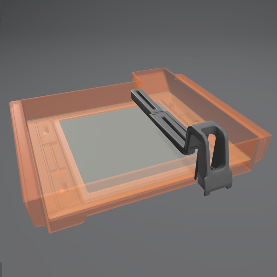 |
| Tank grips | Plastic handles on each side of the resin tank help to more easily insert, remove, and carry the tank. Avoid touching the bottom of the resin tank, as fingerprints can leave smudges that obstruct the optical path. |  |
| Tank spout | This spout at the back of the resin tank sits underneath the cartridge dispense hole and receives resin from the cartridge. | 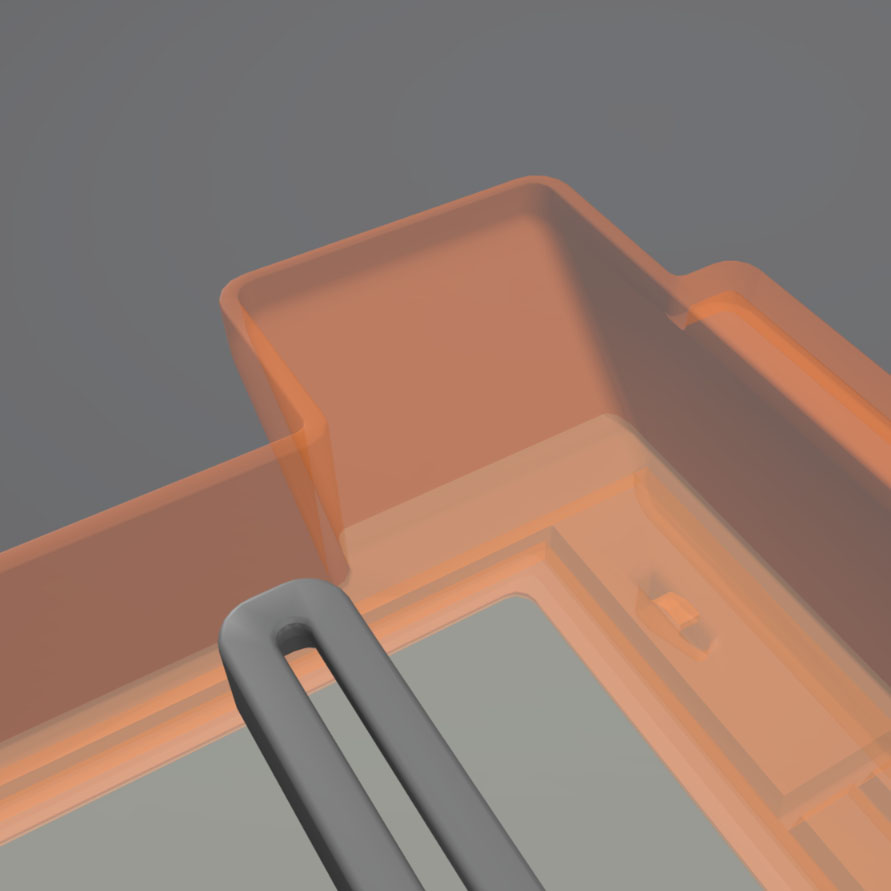 |
| Elastic layer | A coating of elastic material on the bottom of the tank enables a smooth peeling process. Ce matériau peut s'opacifier au fur et à mesure des impressions. Il faudra alors changer le bac. | 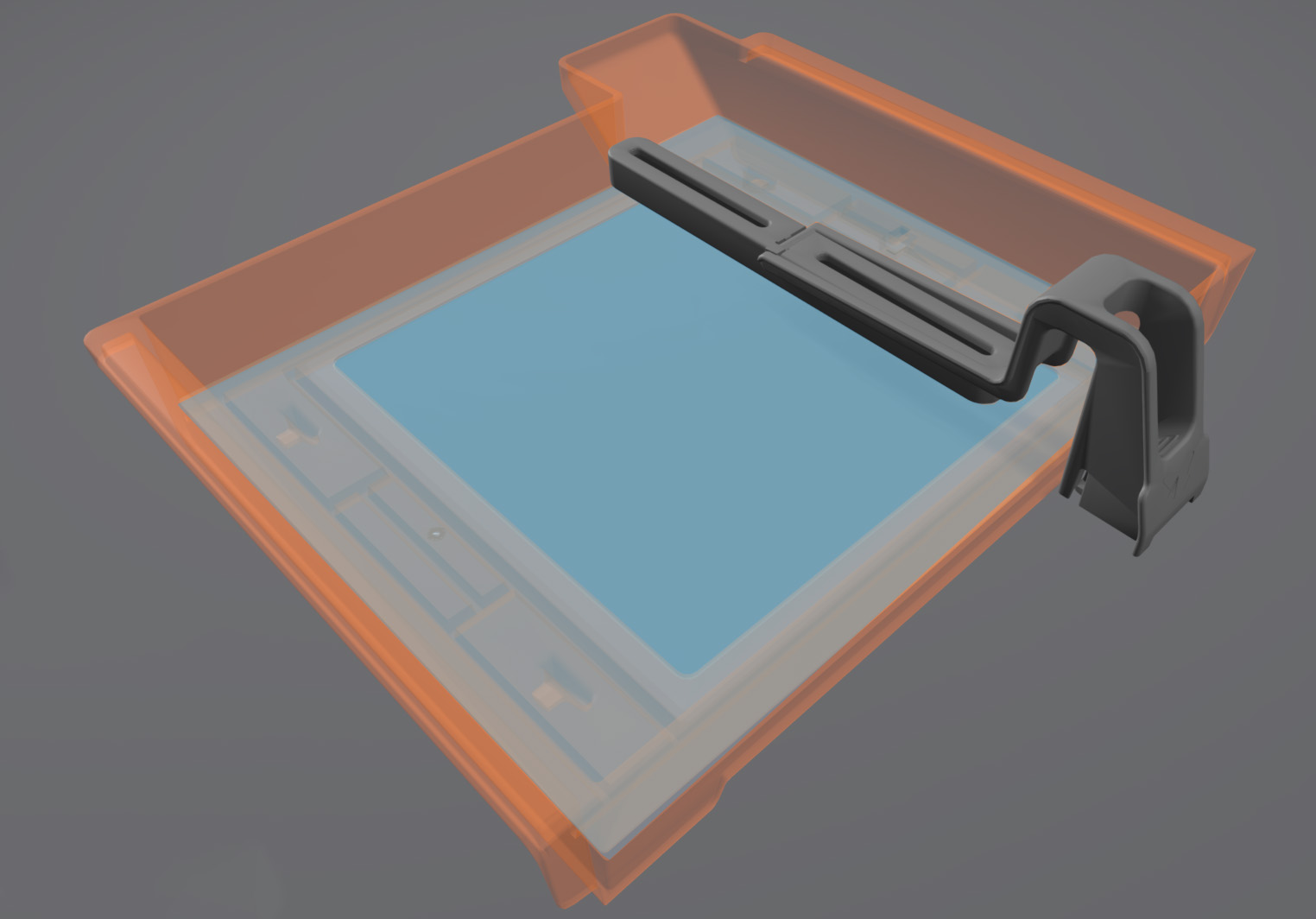 |
| Resin tank ID chip | The resin tank's ID chip uses Electrically Erasable Programmable Read-Only Memory (EEPROM). Les contacts à ressort du bac lisent ce circuit pour déterminer l’identifiant unique du bac et le type de résine qu’il contient. |  |
| Wiper | Each resin tank includes a wiper. The wiper improves print consistency by clearing the build area after each layer and circulating the resin. | 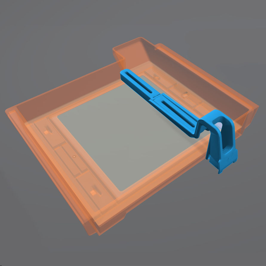 |
| Insertion foot | The insertion foot is located on the bottom of the wiper and holds the wiper to the wiper mount. | 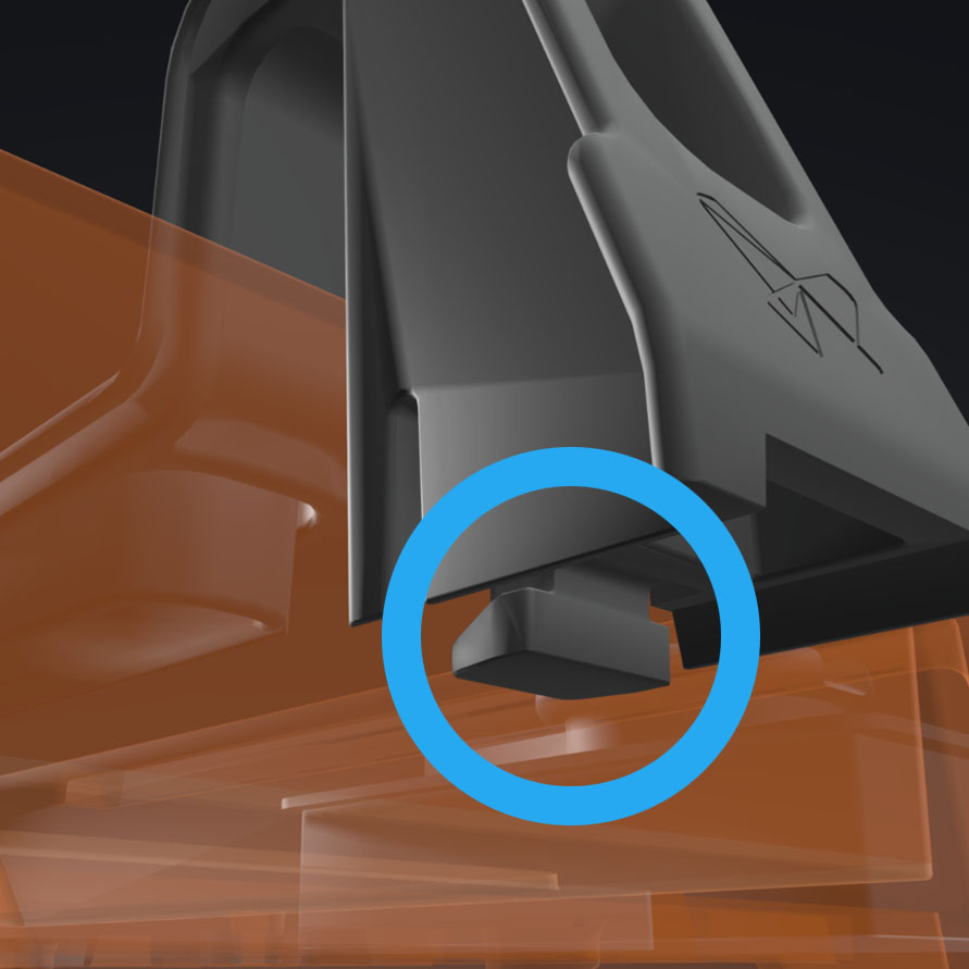 |
| Wiper mount | The wiper mount connects the wiper to the belt drive system. Insert the wiper's insertion foot into the metal bracket before printing. | 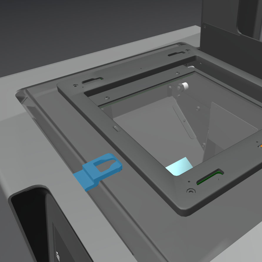 |
Vitre optique
| Item | Description | Image |
| Optical window | Located underneath the resin tank, the optical window is a glass plate with an anti-reflective coating. It protects the sensitive mirrors inside the printer from dust and other contamination. Maintain a clean optical window to prevent print failures. | 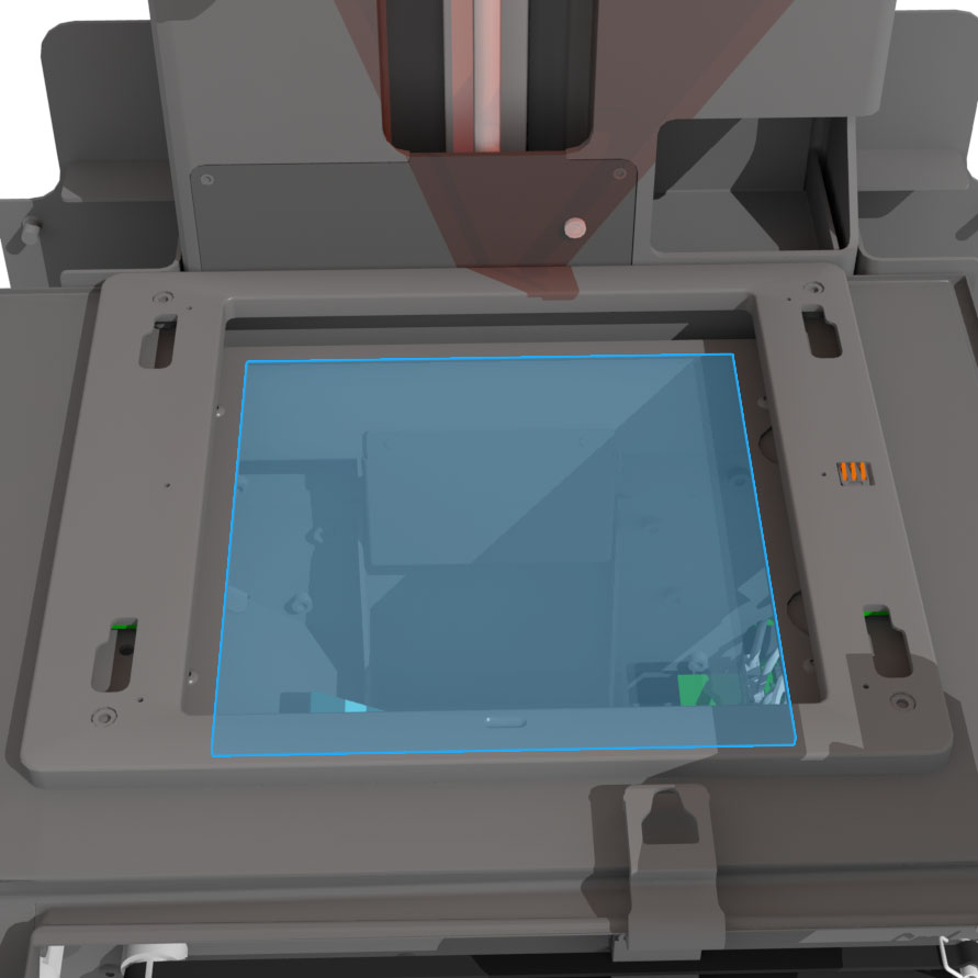 |
Le support mobile du bac
| Item | Description | Image |
| Tank carrier | The tank carrier holds the resin tank and slides left and right during the peel process. Each printer's alignment is uniquely calibrated at the factory. Any change to this alignment via unscrewing or tampering may cause print issues that can only be resolved by a return for re-calibration. |  |
| Shuttle cover | The shuttle cover protects the interior of the printer from spilled resin. It can catch up to 50 mL of resin in the trough located at the front, just under the printer's shell. |  |
| Tank spring fingers | These electrical contacts are embedded in the tank carrier. They read the resin tank's EEPROM ID chip to sense the tank's presence and to communicate the resin type to PreForm. |  |
Carte mère
| Item | Description | Image |
| Motherboard | The motherboard is the main circuitry through which all systems in the printer communicate. |  |
| Power supply | The Form 2 utilizes a 100–240 V power supply. L’alimentation interne convertit l’alimentation secteur en + 24 V CC. |  |
| Motor drivers | Located on the motherboard, these three small chips control the three stepper motors in the machine (build platform, wiper, and tank carrier). Chacun d'eux est branché au moteur correspondant par un connecteur, situé juste devant lui. | 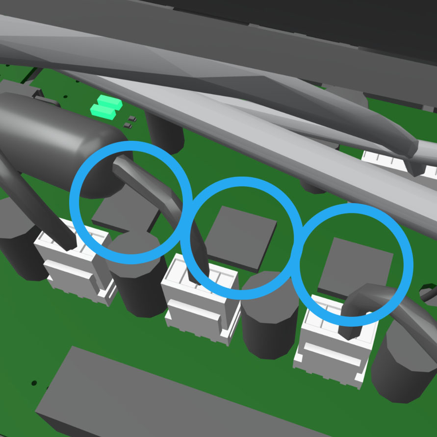 |
| To front display (connector) | This connector links the display to the motherboard via a ribbon cable. |  |
| Wi-Fi antenna | The Wi-Fi antenna enables the Form 2's wireless connectivity. Elle pointe par un trou sur la carte mère de l'imprimante. | 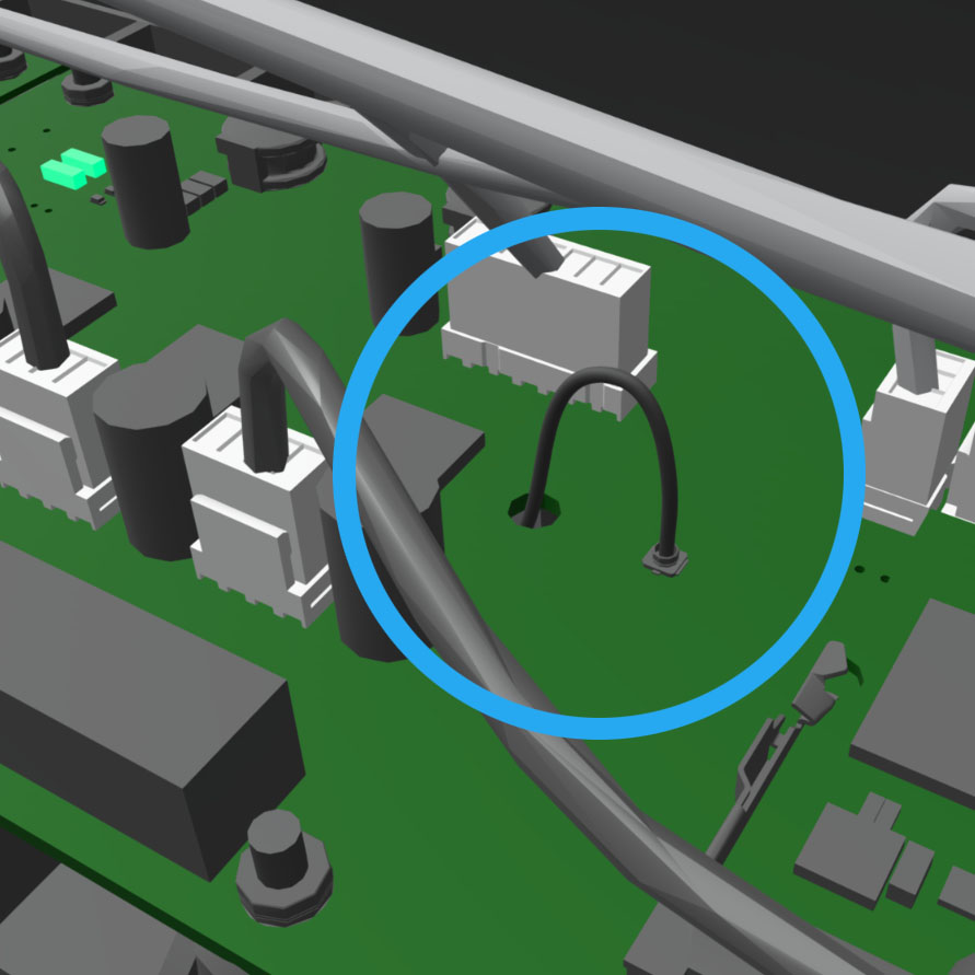 |
| Ethernet port | The Form 2 can connect to a network via Ethernet. Le port est connecté à la carte mère et se trouve à l’arrière de l’appareil. |  |
| USB port | The Form 2 can connect to a computer via USB. Le port est connecté à la carte mère et se trouve à l’arrière de l’appareil. | 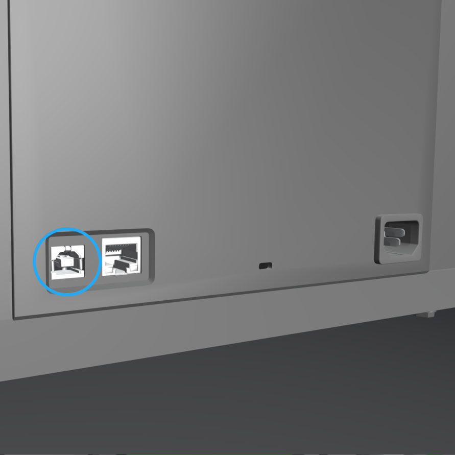 |
Wiper actuator
| Item | Description | Image |
| Wiper belt | This geared rubber belt connects the wiper mount to the wiper motor. As the motor turns, the belt moves the wiper back and forth across the resin tank. |  |
Capteur de niveau de résine
| Item | Description | Image |
| LevelSense board | The black panel behind the resin tank measures and regulates the refill rate of the resin in the tank. Any contamination can affect its accuracy and may lead to problems printing. Clean the LevelSense board with a small amount of clean IPA if contaminated. |  |
| Thermopile | The thermopile is an infrared (IR) sensor located on the LevelSense board that senses resin tank temperature. Si elle est salie par de la résine, veuillez contacter l’assistance. |  |
Optique
| Item | Description | Image |
| Shrouds (baffles) | These flexible plastic shields enclose and protect the printer's internal components, especially the optical path. The shrouds are attached by reusable plastic rivets. |  |
| Laser | The laser is the source of curing energy in the Form 2. It has a 405 nm violet diode and a maximum output of 250 mW. The Form 2 is a Class 1 laser product. |  |
| Galvanometers (a.k.a. galvos) | The galvanometers are small, fast, and precise motors that guide the laser. One controls the movement of the laser in the Y-axis, and the other controls the X-axis. | 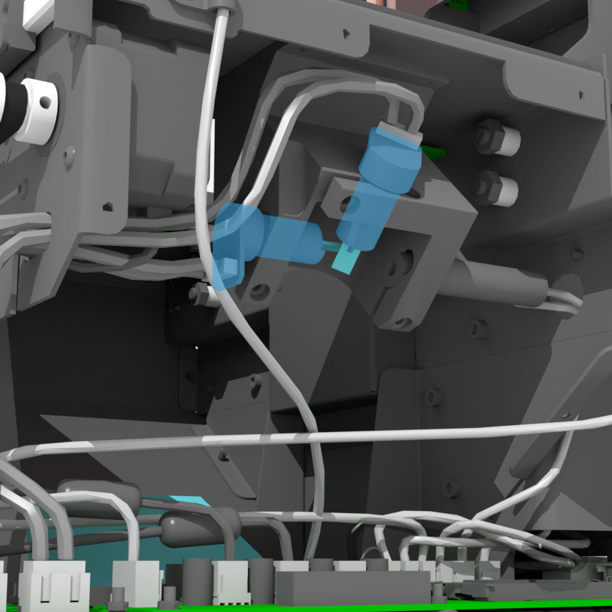 |
| Galvo mirrors | These small mirrors are affixed to the galvanometer rotors to guide the laser toward the main mirror. |  |
| Main mirror | After reflecting off the galvo mirrors, the laser is redirected up through the optical window and resin tank to cure the resin. |  |