Replacing the Fuse Sift cartridge drawer latch, board, and sensors

The Fuse Sift relies on the latch and sensors on the cartridge drawer to ensure that a powder cartridge is inserted and the drawer is closed before dispensing powder. If any of these components or the board the sensors plug into are faulty or damaged, the Fuse Sift may be unable to dispense powder properly.

Use this guide to replace the Fuse Sift cartridge drawer latch, board, and sensors.

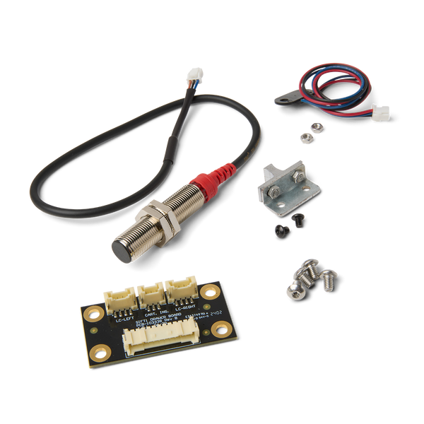
Fuse Sift cartridge drawer kit

Required Supplies:

Formlabs:

Third-party:

  • 2 mm hex driver (flat-end)
  • 2.5 mm hex driver (flat-end)
  • #2 Phillips driver
  • 5.5 mm compact socket wrench (recommended) or box wrench
  • 7 mm compact socket wrench (recommended) or box wrench
  • Flush cutters
  • Adjustable wrench
  • Zip ties
  • Double-sided foam tape (optional)
  • Antistatic wrist band
  • Appropriate personal protective equipment for the powder in use, as defined in the safety data sheet (SDS)
  • Nonreactive nitrile gloves
  • Non-abrasive lint-free wipes
  • Loctite 243 or equivalent threadlocker
Estimated time: 30–45 minutes

Preparing the workspace

Overview: Prepare the Fuse Sift and your workspace for replacing the components included in the cartridge drawer kit.

Step 1: Update the Fuse Sift's firmware

Update the machine's firmware to the latest version available prior to installing the replacement parts.

Step 2: Clean the workspace

Using the vacuum attached to your Fuse Sift, clean the workspace. Vacuum any loose powder inside the workspace, under the hood, on the print bed and the surrounding port, and on the vent filter.

Warning:

Use appropriate personal protective equipment when handling loose or unsintered powder. Refer to the support article Safety with Formlabs SLS products or your powder’s safety data sheet (SDS) for more information.

Removing the rear enclosure panel

Overview: Remove the rear enclosure panel to better access the cartridge drawer components.

Step 1: Unplug the Fuse Sift

Power off the Fuse Sift, then unplug the power cable from the rear panel.

Danger:

Performing this procedure on the Fuse Sift while it is plugged in increases the risk of electric shock. After disconnecting the power from the Fuse Sift, wait at least five minutes before servicing.

Step 2: Unscrew the Wi-Fi antenna

Remove the Wi-Fi antenna, if present.

Step 3: Remove the rear enclosure panel

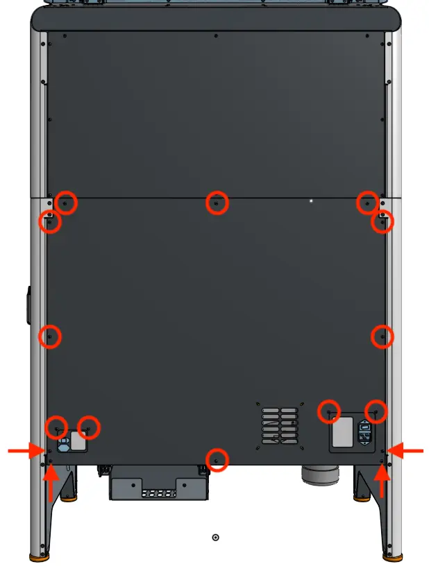
Use a 2.5 mm hex driver to remove the 16 black 8.0 mm M4 screws securing the rear panel to the Fuse Sift. Set the rear enclosure panel aside.

Fuse sift rear enclosure panel

Tip

Remove the top three screws last to prevent the panel from falling off.

Notice: 

The Fuse Sift contains sensitive electronic components. Ground yourself before touching any electronics in the device by using an antistatic wrist band.

Removing the cartridge drawer

Overview: Separate the cartridge drawer from the Fuse Sift and unplug the cables from the cartridge drawer board.

Step 1: Unscrew the cartridge drawer mounting screws

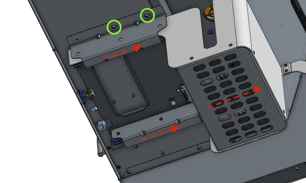
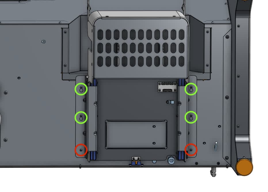
From the back of the Fuse Sift, look under the machine and locate the six 10.0 mm chrome M4 button head screws securing the cartridge drawer to the machine.

Using a 2.5 mm hex driver, loosen and remove the two screws closest to the back of the machine. Set the screws aside. Loosen the remaining four screws but do not remove them.

Remove the cartridge drawer

Step 2: Separate the cartridge drawer from the Fuse Sift

Remove the cartridge drawer

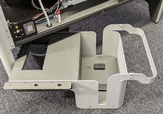
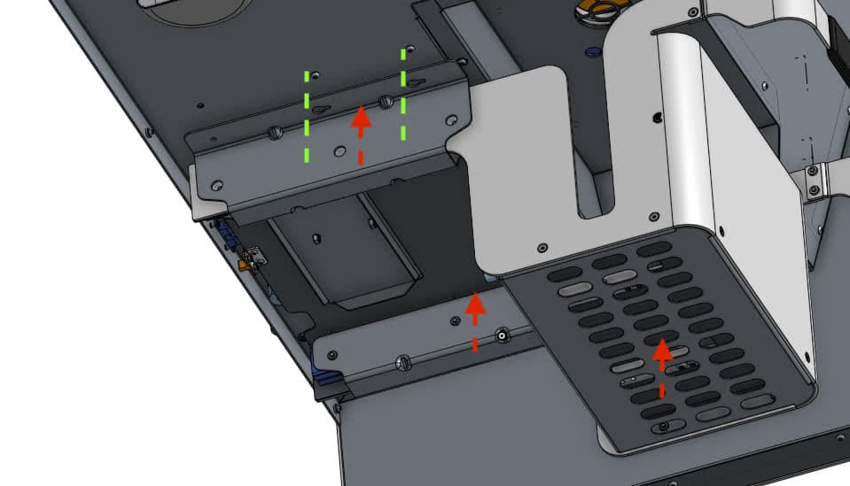
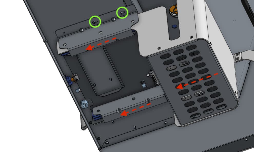
Grab both rails and slide the entire cartridge drawer assembly forward towards the front of the machine until the remaining screws clear the drawer flange mounting slots.

Carefully set the cartridge drawer assembly down below the machine. Do not strain or damage the cables that still connect the drawer to the Fuse Sift.

Caution:

The drawer slides can now move freely and may pose a pinching hazard.

Step 3: Replace the necessary cartridge drawer components

If you have not already, put on an antistatic wrist band and connect it to a known ground point. Do not connect the wristband any surfaces that are powder-coated or painted. Follow the steps in the following sections to replace individual cartridge drawer components as needed:

Replacing the cartridge drawer board

Overview: Remove and replace the cartridge drawer board, which connects the cartridge drawer load cells and Hall effect sensor to the Fuse Sift motherboard.

Step 1: Disconnect the cables from the cartridge drawer board

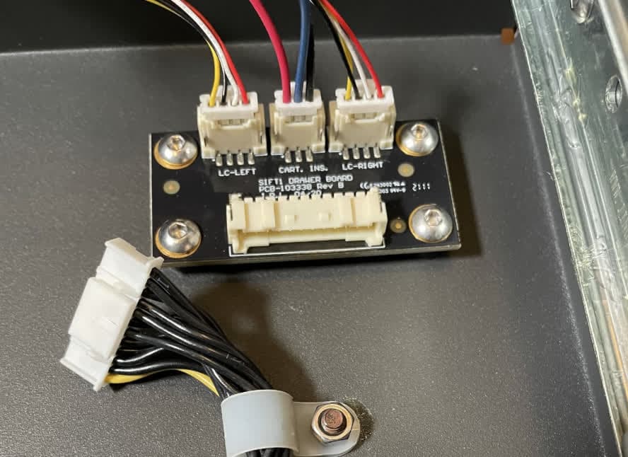
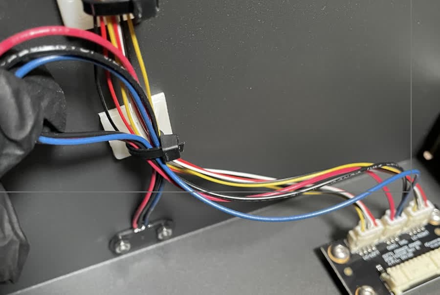
Locate the cirbuit board on the underside of the cartridge drawer, towards the back. Disconnect all four cables from the board: two for the load cells, one for the Hall effect sensor, and one to connect the board to the Fuse Sift motherboard. Take note of which cable connected to LC-LEFT and which connected to LC-RIGHT.

Take care when unplugging each cable to avoid damage. Once the plastic tab is pressed, the cable will easily slide from the connector. Do not pull on the wires.

A cable management clip secures the motherboard cable to the cartridge drawer. If necessary, remove the 7 mm nut that holds the clip closed to make it easier to unplug the cable.

Replacing Sift Drawer Board and Hall Effect Sensor

Step 2: Remove the cartridge drawer board

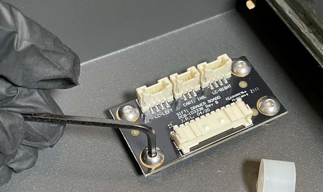
Using a 2.5 mm hex driver, remove the four M4 screws securing the board to the cartridge drawer. The M4 screws are secured with threadlocker, so ensure the hex driver fits securely to prevent stripping the screw. Set the screws and board aside for disposal.

Replacing Sift Drawer Board and Hall Effect Sensor

Step 3: Mount and secure the replacement cartridge drawer board

Place the new cartridge drawer board on its standoffs, with the wide cable connector facing the cable management clip. Apply a small dab of Loctite 243 or similar threadlocker to each of the cartridge drawer screws included in the kit. Thread one into each of the four screw holes in the board, then tighten with a 2.5 mm hex driver until snug.

Step 4: Connect the cartridge drawer cables

Connect the four cables to the new cartridge drawer board. Each cable only fits into its connector in the correct orientation. If you previously opened the cable management clip, close it around the motherboard cable and secure it in place with the 7 mm nut.

Replacing the Hall effect sensor

Overview: Remove and replace the Hall effect sensor, which detects whether a powder cartridge is inserted.

Step 1: Separate the Hall effect sensor from the Fuse Sift frame

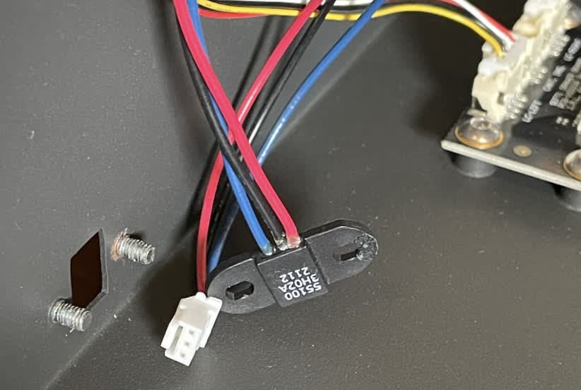
Locate the Hall effect sensor, a small black oval positioned near the cartridge drawer board. Using a 5.5 mm compact socket wrench, loosen and remove the two nuts that secure the Hall effect sensor to the drawer. Set the nuts aside for disposal.

Replacing Sift Drawer Board and Hall Effect Sensor

Step 2: Unplug the Hall effect sensor

Carefully cut the zip tie securing the cartridge drawer sensor cables. Unplug the Hall effect sensor from the nearby cartridge drawer board.

Replacing Sift Drawer Board and Hall Effect Sensor

Step 3: Mount and secure the replacement Hall effect sensor

Mount the new Hall effect sensor with the convex face inserted into the cutout in the drawer. Secure the sensor with the two M3 5.5 mm nuts.

Step 4: Connect the Hall effect sensor

Connect the Hall effect sensor cable to the nearby board. Secure the sensor cables together with a zip tie.

Replacing the cartridge drawer latch

Overview: Remove and replace the half of the latch mounted to the cartridge drawer.

Step 1: Separate the latch from the cartridge drawer

Replacing the Grab Latch and Bracket

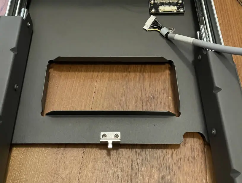
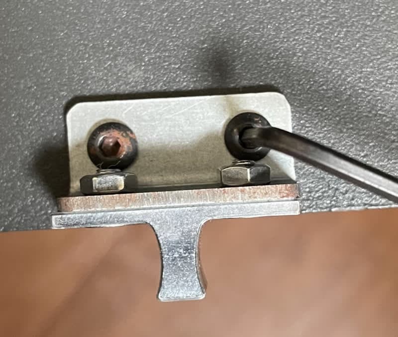
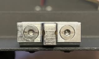
Locate the portion of the latch mounted to the underside of the cartridge drawer. Using a 2 mm hex driver, loosen and remove the two black 2 mm M3 screws securing the latch and bracket to the drawer. Set the latch and screws aside for disposal.

Step 2: Mount and secure the replacement latch

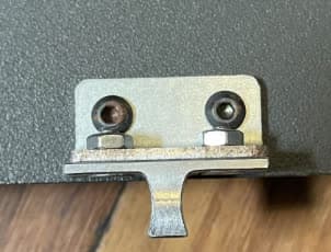
Align the screw holes in the replacement latch with the corresponding screw holes in the cartridge drawer. Apply a small dab of Loctite 243 or similar threadlocker to each of the latch screws included in the kit. Thread one into both of the screw holes in the latch, then tighten with a 2 mm hex driver until snug.

Replacing the Grab Latch and Bracket

Replacing the inductive sensor

Overview: Remove and replace the inductive sensor that detects when the cartridge drawer is closed.

Step 1: Remove the motherboard cover

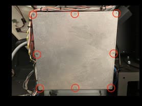
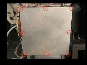
Locate the square motherboard cover on the rear of the machine. Using a #2 Phillips driver, loosen and remove the eight countersunk screws securing the cover onto the motherboard enclosure. Set the screws and cover aside.

Replace Inductive Sensor

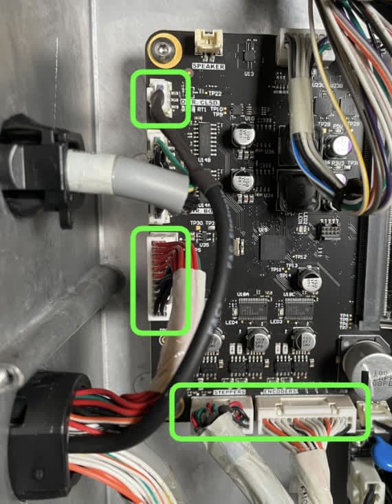
Step 2: Disconnect inductive sensor and motor cables from the motherboard

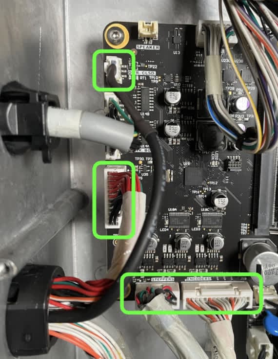
Disconnect the black inductive sensor cable as well as the three cables labeled CBL-103866-02, CBL-103861-01, and ENCODERS from the left side of the motherboard.

Replace Inductive Sensor

Step 3: Separate the inductive sensor cable from other wires

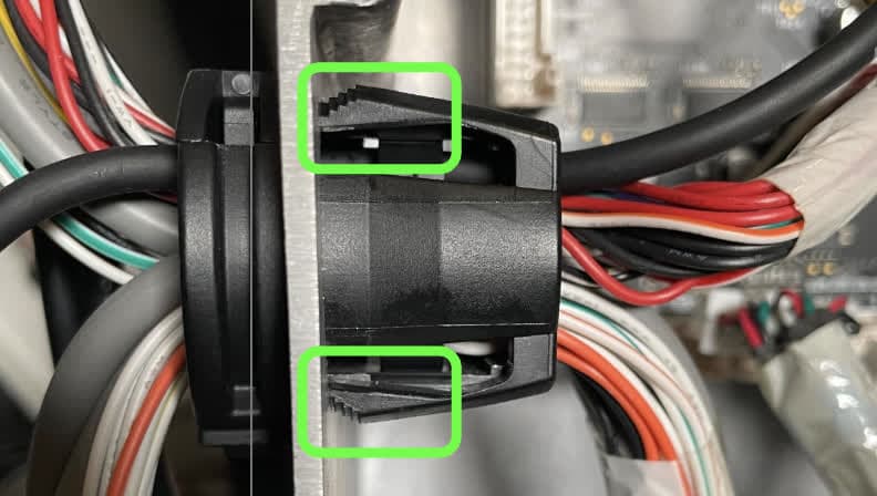
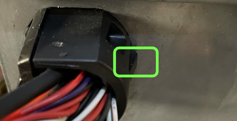
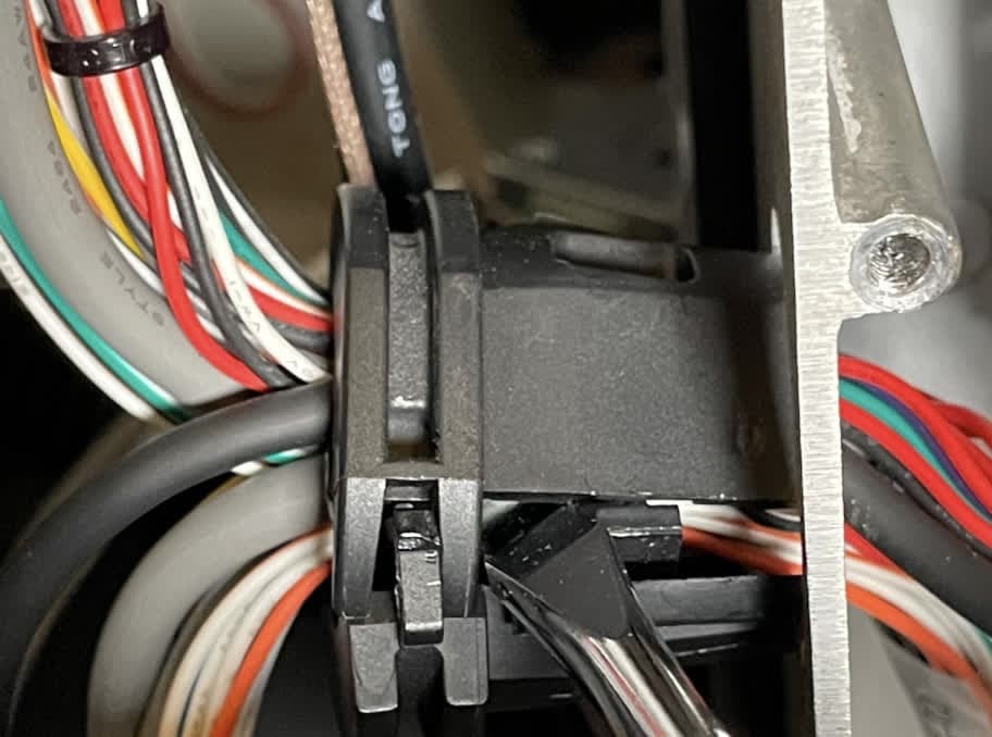
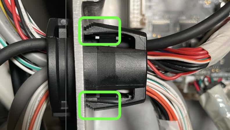
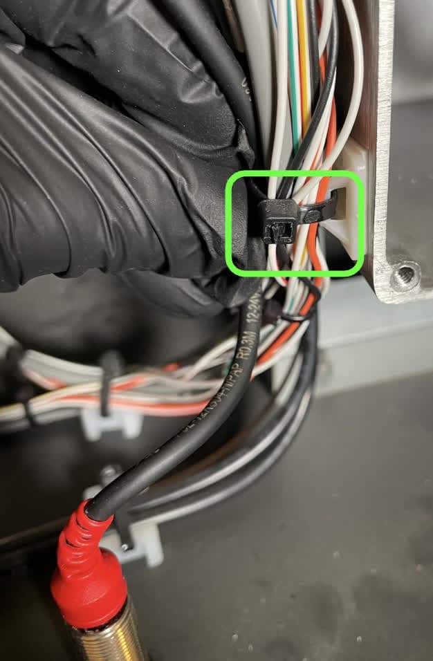
Locate the cord holder passing through the left side of the motherboard enclosure. Squeeze the three retention tabs and push it through to the outside of the enclosure.

Replace Inductive Sensor

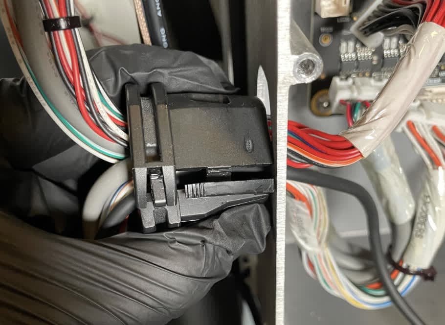
Pull the cord holder out of the hole. Gently pry open the cord holder with a flat-head screwdriver or other thin tool. Open the cord holder and remove the black inductive sensor cable. Locate the zip tie securing the cable outside the enclosure. Carefully cut the zip tie and pull the cable out of the motherboard enclosure.

Replace Inductive Sensor

Step 4: Remove the inductive sensor

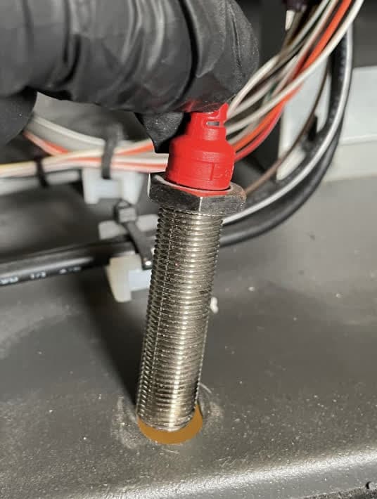
Follow the inductive sensor cable to the sensor itself. The sensor is secured to the Fuse Sift frame with two 17 mm lock nuts. Loosen and remove the bottom lock nut, located under the machine, the pull the inductive sensor up and out of its hole. Loosening the top lock nut may help you better access the bottom lock nut. Set the nuts and sensor aside for disposal.

Replace Inductive Sensor

Step 5: Mount the replacement inductive sensor

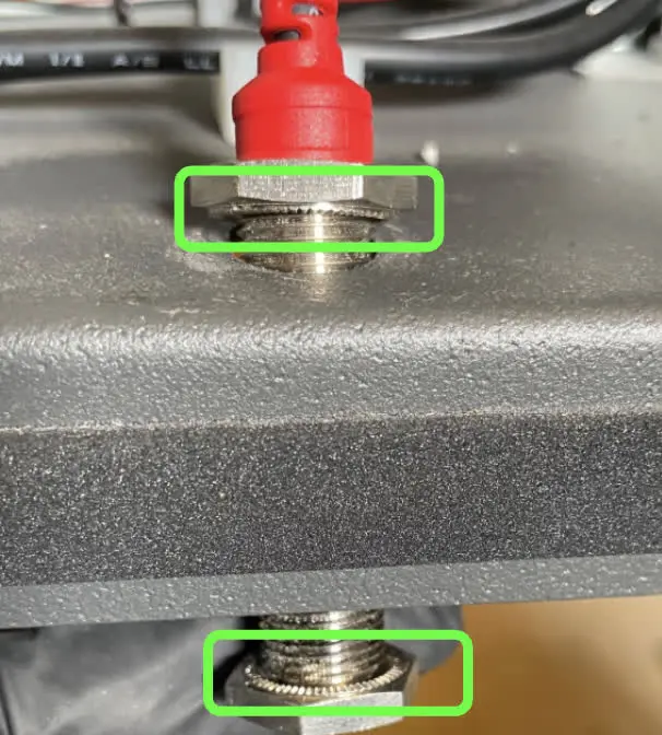
The cartridge drawer kit includes the inductive sensor as well as two lock nuts. Thread one nut onto the sensor with the serrated teeth facing down, away from the red section of the sensor. Lower the sensor into its hole.

Step 6: Secure the inductive sensor

Thread the second lock nut onto the bottom of the sensor with the serrated teeth facing up, towards the bottom of the Fuse Sift. Thread the nut onto the sensor until the lower face of the nut is flush with the bottom of the sensor.

Hold the sensor and lock nut against the bottom of the Fuse Sift, then tighten the top lock not until the sensor is secure.

Replace Inductive Sensor

Step 6: Route the inductive sensor cable

Replace Inductive Sensor

Bundle the inductive sensor cable with the other cables in the cord holder. Squeeze the cord holder shut. Route the inductive sensor cable connector into the motherboard enclosure, then press the cord holder into its hole until retention tabs click into place. Collect the cables that were previously secured with a zip tie and secure them with a new zip tie.

Step 7: Reconnect the cables to the motherboard

Connect the black inductive sensor cable and the cables labeled CBL-103866-02, CBL-103861-01, and ENCODERS to their respective connectors on the motherboard.

Replace Inductive Sensor

Step 8: Reinstall the motherboard cover

Mount the motherboard cover onto the enclosure, aligning the eight screw holes in the cover with the corresponding ones around the enclosure. Thread one countersunk screw into each of the screw holes, then use a #2 Phillips driver to tighten until snug.

Replace the MoBo enclosure cover

Reinstalling the rear enclosure panel

Overview: Mount and secure the rear enclosure panel after installing the new cartridge drawer components.

Step 1: Prepare the rear panel retention screws

Apply a small amount of Loctite 243 or other similar threadlocker to each of the 16 black 8.0 mm M4 button screws that secure the rear panel to the Fuse Sift.

Step 2: Mount the rear panel

Mount the rear panel onto the Fuse Sift.

Step 3: Secure the rear panel

Thread one 8.0 mm M4 button screw into each of the 16 screw holes in the rear panel. Use a 2.5 mm hex driver to tighten until

Fuse sift rear enclosure panel

Tip:

Start with the top three screws to hold the panel in place while you thread and tighten the remaining screws.

Reinstalling the cartridge drawer

Overview: After replacing the cartridge drawer components, mount and secure the cartridge drawer.

Step 1: Mount the cartridge drawer

Mount the cartridge drawer

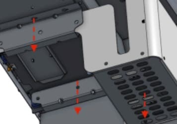
From the back of the machine, guide the drawer assembly upward onto the underside of the machine so the four mounting slots align with the remaining four chrome 10.0 mm M4 button screws.

Grab both rails to slide the entire drawer backward towards the back of the machine until the screws engage all four drawer flange mounting slots.

Step 2: Secure the cartridge drawer

Apply a small dab of Loctite 243 or equivalent threadlocker onto both of the remaining chrome 10.0 mm M4 cartridge drawer mounting screw. Thread one screw into both of the remaining screw holes in the cartridge drawer flanges. Using a 2.5 mm hex driver, tighten all six screws until snug.
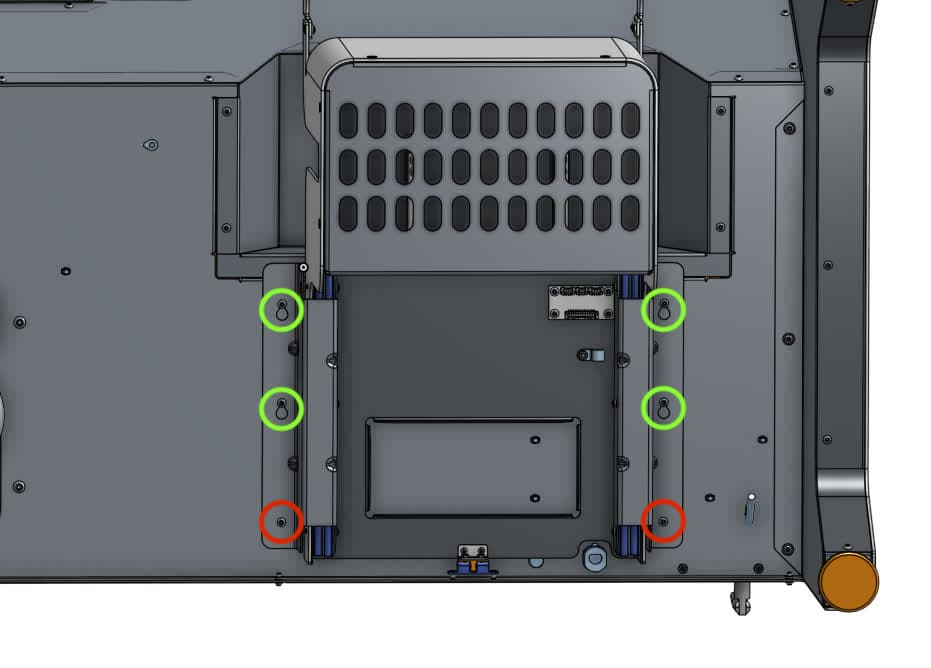
Secure the cartridge drawer

Finalizing the repair

Overview: After installing the new cartridge drawer components, power on the Fuse Sift and test its functions.

Step 1: Power on the Fuse Sift

Reconnect the Fuse Sift to its power source. Flip the power switch to the ON position.

Step 2: Insert a powder cartridge

Insert a powder cartridge into the cartridge drawer. Close the drawer and ensure that it latches, the Fuse Sift recognizes the cartridge, and you can dispense powder into the cartridge.