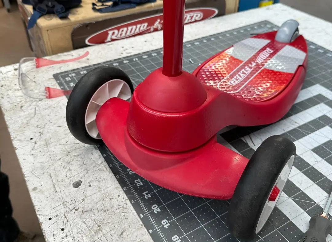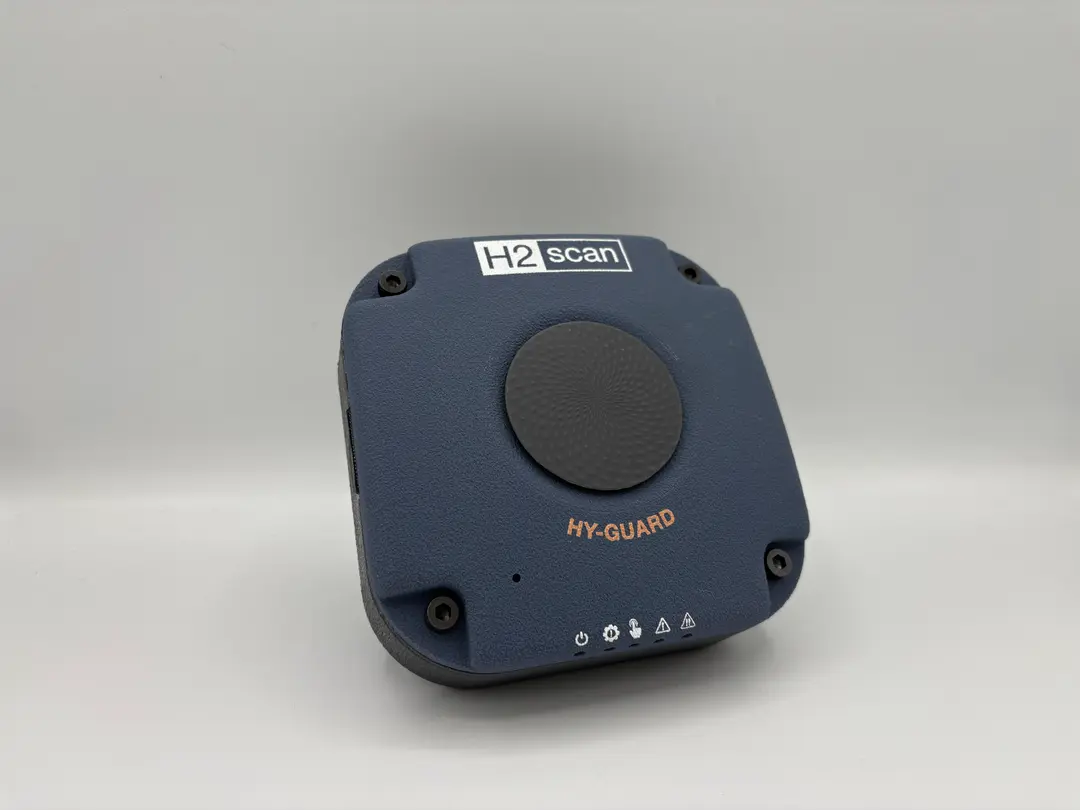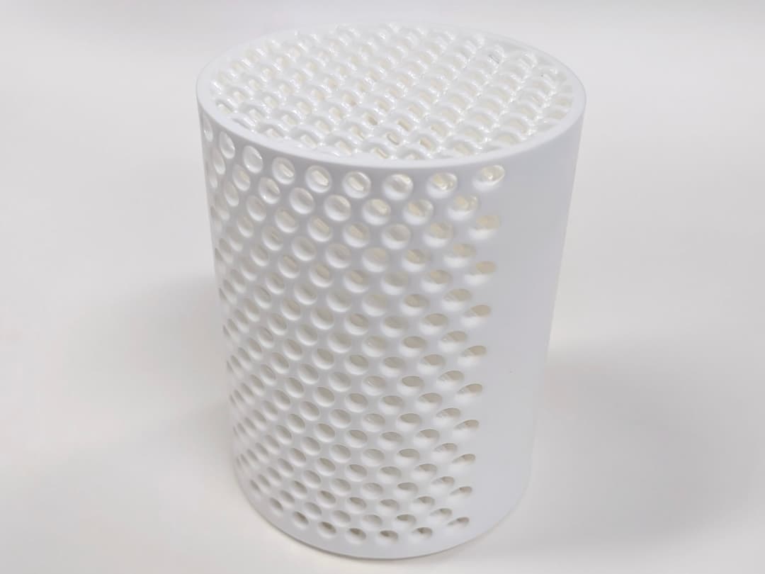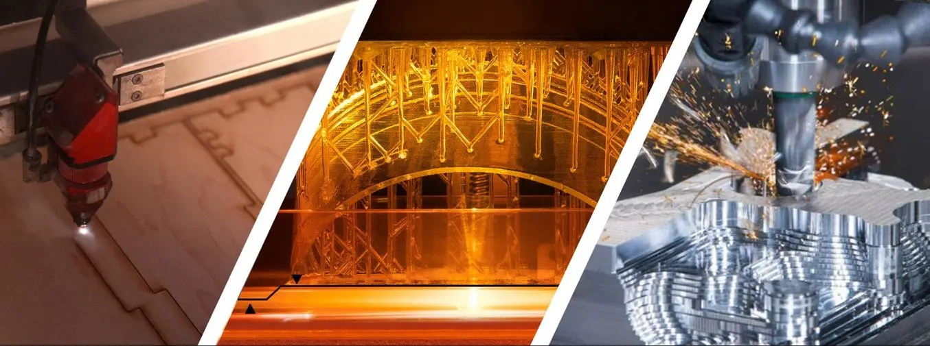
Digital fabrication is a design and manufacturing workflow where digital data directly drives manufacturing equipment to form various part geometries. This data most often comes from CAD (computer-aided design), which is then transferred to CAM (computer-aided manufacturing) software. The output of CAM software is data that directs a specific additive and subtractive manufacturing tool, such as a 3D printer or CNC milling machine.
A wide variety of digital fabrication tools exist, from hobbyist-level machines to large-scale, specialized industrial equipment used in manufacturing. This guide focuses on the most common tools suitable for professional workspaces, machine shops, and workshops.
Accessible digital fabrication tools bridge the gap between design and manufacturing. As barriers to professional-level tech lowers, it’s easier for anyone with the skills to design a product to also fabricate it, empowering engineers, product designers, and businesses of all sizes to produce anything from prototypes to final products.
In this definitive guide, learn the ins and outs of digital fabrication from workflows to digital fabrication tools and practical tips for getting started.
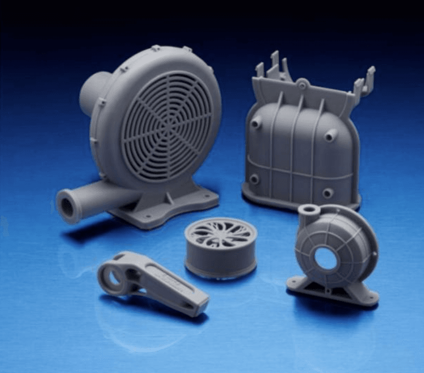
Introduction to 3D Printing for Engineers and Manufacturers
In this webinar, learn how parts created from various printing technologies differ across functionality and appearance, and how these differences impact product development and production workflows for engineers and manufacturers.
Watch the Webinar NowHow Does Digital Fabrication Work?
1. Design
The first step is to create a digital design using CAD software. To serve as input for the fabrication tool, the 3D model is exported as a triangulated mesh, which uniformly describes the geometry in terms of points on the surface or vertices, the faces between those vertices, the edges of those faces, and in some cases, the normal vectors and color information pertaining to the faces.
2. Prepare
Print preparation software or slicer software serves as the intermediate between the virtual mesh and the fabricated model for 3D printing. In this step, manufacturing parameters and settings specific to the fabrication tool are added to provide essentially a list of instructions for the machine to follow, resulting in a CAM file that’s sent to the machine. In machining operations, software simulation is combined with user input to generate toolpaths that will guide the cutting tool through the part geometry, taking into account speed of the cutting tool and feed rate of the material.
3. Fabricate
Fabrication tools manufacture parts based on the CAM data, with little or no human assistance or interaction. The fabricated parts might require some form of finishing to achieve their final properties and look before they’re ready to use.
Digital Fabrication Tools
3D Printers
Additive manufacturing (AM) or 3D printing processes create parts by successively adding material layer by layer until a physical part is created.
Fused deposition modeling (FDM) 3D printers melt and extrude thermoplastic filament, which a print nozzle then deposits layer by layer in the build area. FDM is the most affordable 3D printing technology with entry-level hobbyist machines starting below $1,000, and mid-range machines selling for $2,500. FDM parts have the lowest resolution and accuracy compared to other plastic 3D printers, making these machines a better fit for basic proof-of-concept models and quick, low-cost prototyping of simple parts than for refined prototypes or final products.
Stereolithography (SLA) uses a laser to cure liquid resin into hardened plastic in a process called photopolymerization. SLA parts are highly accurate, have fine details, smooth surface finish, and isotropic material properties. SLA 3D printing is ideal for complex designs, functional prototypes, manufacturing tooling, and casting patterns. Starting around $3,500, desktop SLA printers are highly versatile tools that are easy to use and accessible to professional users.
See how stereolithography works.
Selective laser sintering (SLS) 3D printers use a high-powered laser to fuse small particles of polymer powder. The unfused powder supports the part during printing and eliminates the need for dedicated support structures. Parts produced with SLS printing have excellent mechanical characteristics, with strength comparable to injection-molded parts. SLS is the latest plastic 3D printing technology to appear in a smaller, more accessible form, with benchtop systems starting around $10,000.
| Fused Deposition Modeling (FDM) | Stereolithography (SLA) | Selective Laser Sintering (SLS) | |
|---|---|---|---|
| Accuracy | ★★★★☆ | ★★★★★ | ★★★★★ |
| Surface Finish | ★★☆☆☆ | ★★★★★ | ★★★★☆ |
| Complex Designs | ★★★☆☆ | ★★★★☆ | ★★★★★ |
| Ease of Use | ★★★★★ | ★★★★★ | ★★★★☆ |
| Materials | Standard thermoplastics, such as ABS, PLA, and their various blends | Varieties of resin (thermosetting plastics), ABS-like, PP-like, flexible, heat-resistant, castable (wax-like) | Engineering thermoplastics, such as nylon and its composites |
| Applications | Low-cost rapid prototyping Basic proof-of-concept models | Functional prototyping Manufacturing tooling Casting Modelmaking | Functional prototyping Short-run, bridge, or custom manufacturing |
Read our in-depth guide to compare of FDM, SLA, and SLS technologies.
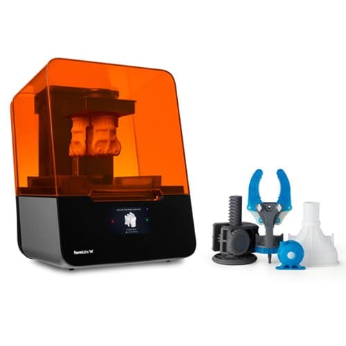
Introduction to 3D Printing With Desktop Stereolithography (SLA)
Download our white paper to learn how SLA 3D printing technologies work, why thousands of professionals use this process today, and what you need to know to explore how this 3D printing process can benefit your work.
Download White PaperCNC Tools
Subtractive processes start with solid blocks, bars, or rods of plastic, metal, or other materials that are shaped by removing material through cutting, boring, drilling, and grinding. In digital fabrication processes, these tools are driven by computer numerical control (CNC).
CNC machining removes material by either a spinning tool and fixed part (milling) or a spinning part with a fixed tool (lathe). Small CNC machines start around $2,000, but more advanced workshop tools go well beyond that depending on the number of axes, features, part size, and tooling needed for specific materials. CNC machines can create parts out of plastics and metals for functional prototyping, manufacturing tooling, and custom or low-volume end-use parts.
Laser cutters use a laser to engrave or cut through a wide range of materials with high precision. Laser cutters are cost-effective, fast, and easy-to-use tools for engraving and cutting thin, flat-sheet materials for prototypes, mechanical and structural parts. Basic engravers are available for less than $500, while mid-range laser cutters for the workshop that can cut through multiple materials start around $3,500. Laser cutters are often bundled with a driver software which interprets 2D vector drawings.
Water jet cutters use water mixed with abrasive and high pressure to cut through practically any material. Water jet cutting is the latest CNC process to appear in a smaller, more accessible form with prices starting around $20,000, and new projects promise to soon push below $10,000. Water jet cutters can cut thicker sheets than laser cutters and work with hard materials that are normally difficult to cut to the precise shapes using other processes.
| CNC Machining | Laser Cutters | Water Jet Cutters | |
|---|---|---|---|
| Accuracy | ★★★★★ | ★★★★★ | ★★★★★ |
| Surface Finish | ★★★★★ | ★★★★★ | ★★★★★ |
| Complex Designs | ★★★★☆ | ★☆☆☆☆ | ★☆☆☆☆ |
| Ease of Use | ★★★☆☆ | ★★★★☆ | ★★★☆☆ |
| Materials | Hard thermoplastics, soft thermoset plastics (limited), soft metals, hard metals (industrial machines) | Thermoplastics, wood, acrylic, fabrics, metals (industrial machines) | Plastics, hard and soft metals, stone, glass, composites |
| Applications | Functional prototyping Manufacturing tooling Custom or low-volume end-use parts | Engraving Prototyping Flat mechanical and structural parts | Prototyping Flat mechanical and structural parts |
How to Get Started With Digital Fabrication
CAD
To convert an idea to a digital design, there are several approaches:
Solid modeling is a traditional way of creating 3D objects that is mostly geared towards linear motions to translate design intent into geometries. Solids are combined and finished with transitions to make them directly suitable for digital manufacturing. Advanced features include drafted extrusions, curvature fillets, and patterning operations.
Surface modeling can be performed in most contemporary solid modeling software such as Autodesk Fusion 360, Solidworks, Catia, Rhinoceros, and SolidEdge. In this case, all outside surfaces of the geometry are individually defined, enabling more advanced geometries such as transitions between multiple adjoining surfaces.
3D scanning has become an accessible route to obtaining a 3D printable model. Affordable solutions and new apps that work with camera-based photogrammetry technology provide a great balance between speed, accuracy, and cost. However, scans don’t translate to 3D printable files directly and require extensive post-editing with mesh editing software.
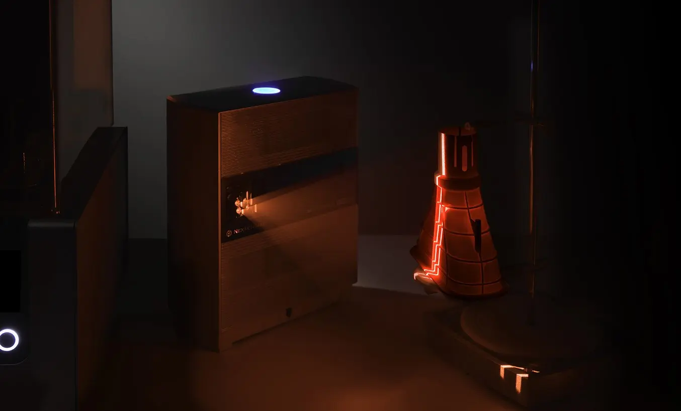
Learn how to use 3D scanning and 3D printing for reverse engineering in our white paper.
Vectors
Two-dimensional systems such as CNC routers and laser cutters can be driven by files exported from vector software such as Adobe Illustrator. Although a fairly comprehensive package, for basic drawing you do not need very advanced skills beyond a familiarity with the pen tool, patterning, live trace, Pathfinder, and a plugin to create rounded corners.
Mesh Preparation
A 3D model leaving a design software package as a mesh model is typically suited for 3D printing already. The key is having a watertight mesh, meaning all triangles are connected and non-overlapping with normals facing the same direction. A solid modeling approach usually results in a watertight mesh, surface modeling, and generative design though require checking the absence of double surfaces and volume collisions.
There are plenty of tools to repair and optimize meshes, such as Meshlab. Ideally, make a small investment in a tool that allows you to edit individual vertices/faces and perform Boolean tasks. Meshmixer is a great free program for optimizing triangle count and allows resculpting your object as well, while Blender allows Boolean operations.
Design for Digital Fabrication
While digital fabrication tools offer a high degree of design freedom, a bit of time spent on optimizing part geometries goes a long way to ensure efficient production and high-quality parts. Make sure to comprehensively study the possibilities and limitations of the machine, material, design software and fabrication process that you are planning to use. Find the time to extensively experiment towards goals that you want to achieve before diving in head-first.
Get Started With 3D Printing
3D printers are easy to use and accessible digital fabrication tools for personal workspaces, machine shops, and workshops.
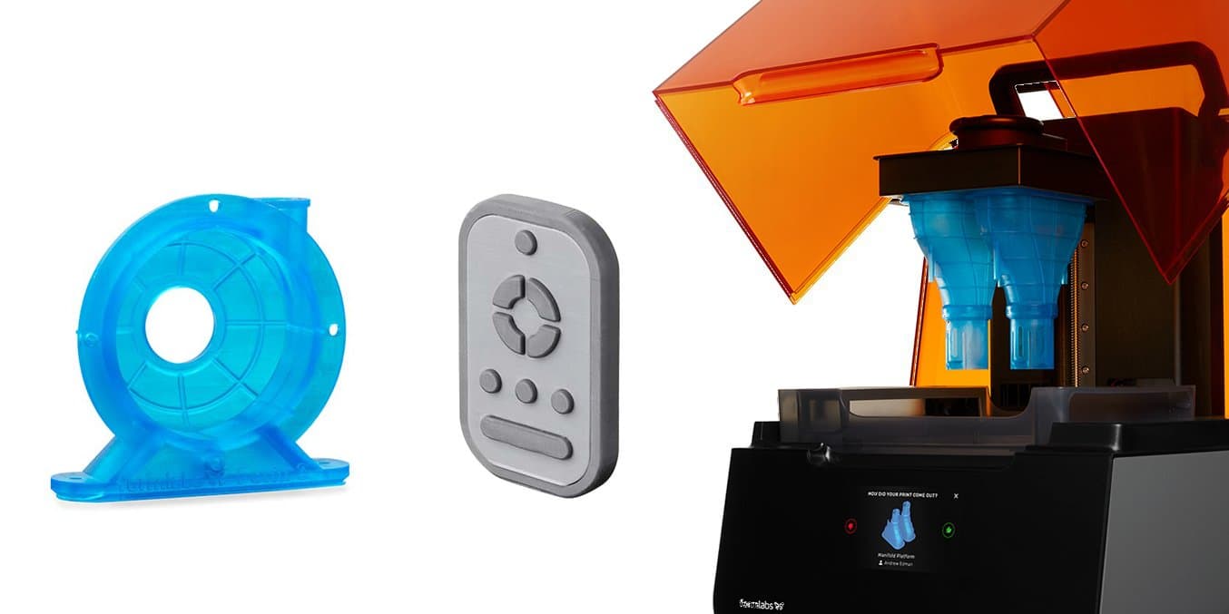
Learn more about 3D printing and see the quality firsthand by requesting a complimentary sample part printed on the Form 3 SLA 3D printer.
