
There are many aspects to consider when preparing an object for 3D printing. Among them is the orientation of the object on the build platform: Is there enough surface area to adhere sufficiently, are unsupported overhangs minimized, and is there enough clearance between objects?
On top of all these considerations, there is yet another if the part is intended to withstand any significant amounts of stress: anisotropy.
Anisotropy, in this context, is defined as having physical properties that vary with respect to direction. For example, a 3D printed object may have different elongations at break or stiffness in the X, Y, and Z directions.
Isotropy vs. anisotropy is a concept discussed often in the 3D printing world, but in some cases the underlying assumptions are based on generalizations.
Often, this kind of content will look only at fused deposition modeling (FDM) printers, which melt polymers that harden into solid final parts, and then make intuitive leaps to expand the idea of structural anisotropy to other printer technologies, like resin-based stereolithography (SLA) 3D printing.
Request a Free SLA Sample Part
See and feel Formlabs SLA quality firsthand. We’ll ship a free sample part to your office.
Why FDM Prints are Anisotropic
3D printers build parts layer by layer, but use different methods to do so. This has significant impacts on the molecular makeup of parts produced by each type of technology.
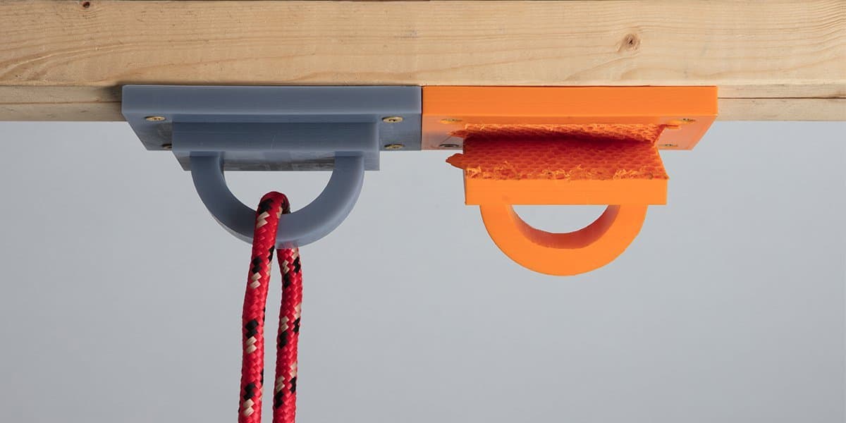
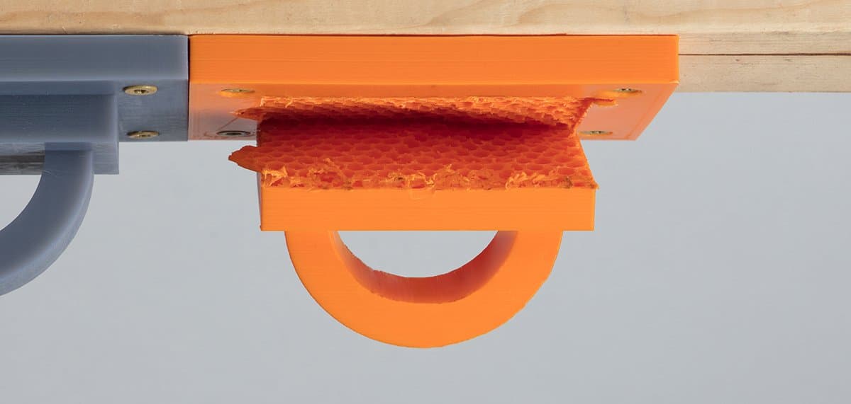
For example, FDM printers melt plastic layers on top of layers. This creates mechanical adhesion (not chemical). As is demonstrated in this experiment, FDM layer surfaces are not fully adhered to each other. Even when the previous layer is partially melted, the surrounding layers are only partially adhered to their neighboring layers.
As a result, the emerging FDM-printed objects have different mechanical properties based on the direction mechanical stress is impacting them and less dense than a similar object produced via alternative methods, such as injection molding. This is also the reason why it is difficult to produce watertight objects via FDM printing: FDM prints are pervaded by microscopic voids and holes.
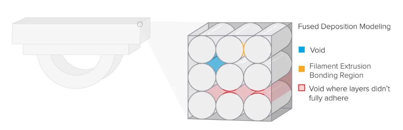
FDM 3D printers form layers by depositing lines of PLA or ABS. This process means that layers are not bonded together as strongly as the lines (filament extrusion) themselves; there are voids in between the rounded lines and it’s possible that layers may not fully adhere to one another.
When viewing this arrangement at a molecular level, there is a clear distinction between the forces inside each layer and the forces that hold the layers together: Each deposited line of PLA or ABS is composed of highly entangled polymer chains which hold together tightly and are therefore pretty strong, tough, and stiff.
As additional lines are deposited to the side or on top of each line it is very difficult, even impossible, to get the same amount of entanglement between the individual lines, thus producing junctions in the filament extrusion bonding regions that are significantly less strong and stiff.
This means that given a particular line deposition pattern, the part will be strongest in the direction of the deposited line and less strong along the axes that are primarily composed of these filament extrusion bonding regions, namely the two spatial axes orthogonal to the line axis.
In short, FDM parts are not equally strong in all directions, and cannot be isotropic, meaning that orientation matters when designing and printing load-bearing parts.
Why SLA Prints are Isotropic: Theory
In resin 3D printing, there is no difference between the chemical bonds that make up the individual layers and the forces that hold the layers together.
As each layer is formed, the resin monomers react and form covalent bonds providing high degrees of lateral strength, but the polymerization reaction is not driven to completion; rather, the print process is modulated in a way that keeps the layer in a semi-reacted state called the “green state.”
This green state differs from the completely cured state in one very important way: there are still polymerizable groups on the surface that subsequent layers can covalently bond to.
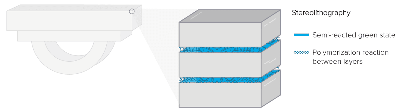
As the next layer is cured, the polymerization reaction will also include the groups on the previous layer, thus forming covalent bonds not just laterally, but also with the previous layer. This crosslinking is typical of all SLA printing processes.
That means that on a molecular level, there is little to no difference between the Z-axis and the XY plane in terms of chemical bonds; each continuous part printed on an SLA machine is a single molecule. Since the SLA lines are fully bonded to their neighbors, there are also no voids or microscopic cracks typical in FDM prints; these prints are watertight and fully dense.
For all intents and purposes, SLA parts prepared in this way are isotropic.
Theory is Good, Practical Data is Better
What does this look like in practice? Do you really not have to worry about how to orient an SLA part if you need it to bear some tension? We decided to put the theory to the test using a Form 2, Clear Resin, and our in-house tensile tester.
We used a tensile tester to measure the differences between maximum strength and Young’s modulus in FDM and SLA prints.
In order to collect the whole spectrum of angles, we printed five ASTM D638 defined type IV tensile bars in 15 degree intervals from 0 (flat relative to the XY plane) to 90 degrees (straight up and down). Each set of bars was washed in isopropyl alcohol (IPA), post-cured, and then clamped into the tensile tester.
Each tensile specimen was tested in accordance with ASTM D638 test method. The tensile tester stretches the bars at a constant speed until they break while recording how much force the bars exert in response. Based on this data, it’s possible to determine a host of material properties, most relevant among them the maximum strength measurement and Young’s modulus.
Maximum stress
Maximum stress is the highest amount of sustained pull that the bar can withstand before it breaks; this is usually what people mean when referring to a material being “strong.”
It’s easy to see how maximum stress could be used as a measure of anisotropy: a part with weak chemical bonds between layers would show significantly diminished strength when the tensile forces are exerted perpendicular to the XY plane.
In fact, that’s exactly what happened in a previous experiment on FDM prints where the Z-axis yield strength of a given part was approximately 55 percent of that in the X-axis.
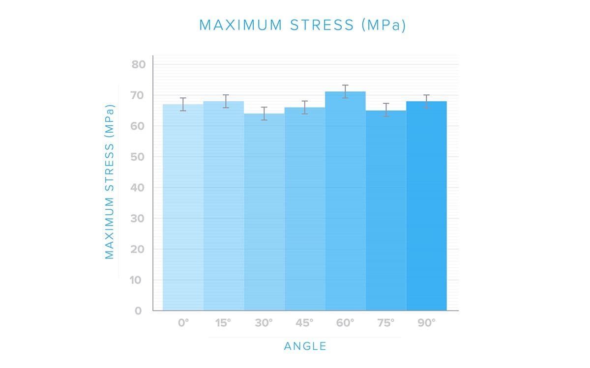
Had the SLA prints been anisotropic we would have expected a decline in maximum stress as the print angle approaches 90 degrees.
To validate the strength findings, we also recorded the Young’s moduli across the print angles.
Young’s moduli
The Young’s modulus is a measure of stiffness and indicates the level of flexibility in an object. It’s particularly important to engineers who may have to make design decisions based on expected stresses and strains in a given application.
As with yield strength, weaker bonds between layers are expected to cause decreases in Young’s modulus, making this another great metric for investigating isotropy in SLA printed parts.
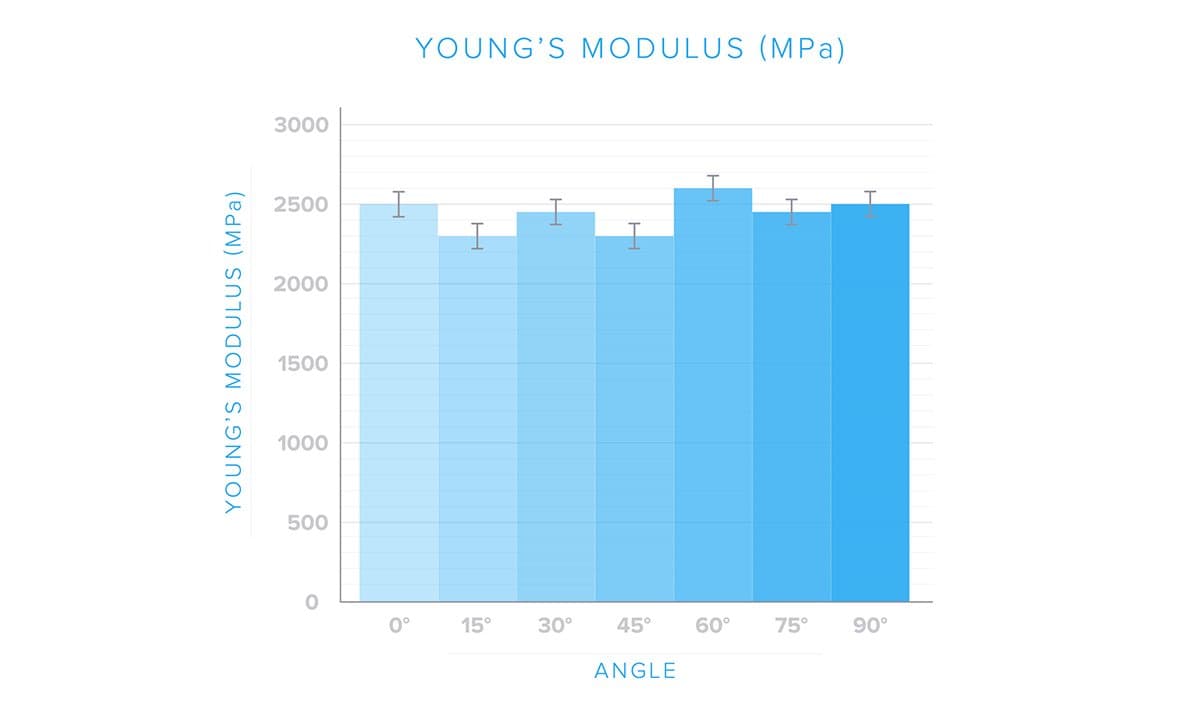
As expected, the Young’s modulus data also falls roughly along a horizontal line, again indicating that print orientation does not have an effect on the material properties of the SLA printed parts, supporting the hypothesis that SLA printed parts are in fact isotropic.
The Verdict: SLA Parts are Isotropic
The evidence points to one conclusion: SLA professional 3D printers produce parts that are as strong and tough in the Z-direction as they are in the X- and Y-directions, no matter how you slice (and then print) them. This makes SLA especially ideal for engineering prototyping applications where material properties matter.
Visit our materials page to learn more about Formlabs Resins, and request a free sample part to experience SLA quality firsthand.