LIVRE BLANC
Formlabs Logo

Editing advanced settings for supports in PreForm

Editing advanced settings for supports in PreForm

Each model has individual needs to address. Configuring support structures to anticipate problems maximizes the chances of a successful print. Use Advanced Settings in PreForm to gain greater control over the amount, size, type, and height of supports generated.

Remarque :

Dans PreForm 3.51.0, Formlabs a introduit un flux de travail de génération de supports entièrement repensé qui offre une expérience plus intuitive et plus puissante, en particulier lors de la modification manuelle des supports. Pour les étapes spécifiques aux versions antérieures de PreForm, développez les sections PreForm 3.50.2 et versions antérieures de cet article.

Resizing the touchpoints

Touchpoints are areas of contact where the support structure and model meet. Decrease the diameter of a touchpoint for easy removal of supports, or increase the diameter for more security during printing.

To adjust the Touchpoint Size value:

  1. Click Supports. A dialog box opens.
  2. To adjust the size of a touchpoint, do one of the following:
    • Enter a number into the Touchpoint Size field.
    • Click an arrow in the Touchpoint Size field.
    • Hover the pointer over the Touchpoint Size field and use the scroll wheel.
  3. Supports V2 only: Select whether or not you want PreForm to use Adaptive Touchtip Diameter when generating supports.
    • With Adaptive Touchtip Diameter enabled, PreForm may deviate from the input Touchpoint Size to better support your models.
    • With Adaptive Touchtip Diameter disabled, PreForm will only use the input Touchpoint Size when generating supports.
  4. If you have no models selected, click Auto-Generate All. Supports are added to all models on the build platform. Otherwise, if you have one or more models selected, click Auto-Generate Selected. Supports are added to the selected models.

Notice:

Parts with an insufficient Touchpoint Size may fail to print. Increase Density to stabilize a part during printing and compensate for a reduced Touchpoint Size. For Supports V1 settings, each support type—for overhangs, stabilization, and reinforcements—has its own density parameter that can be set separately.

Controlling touchpoint placement (Supports V1 only)

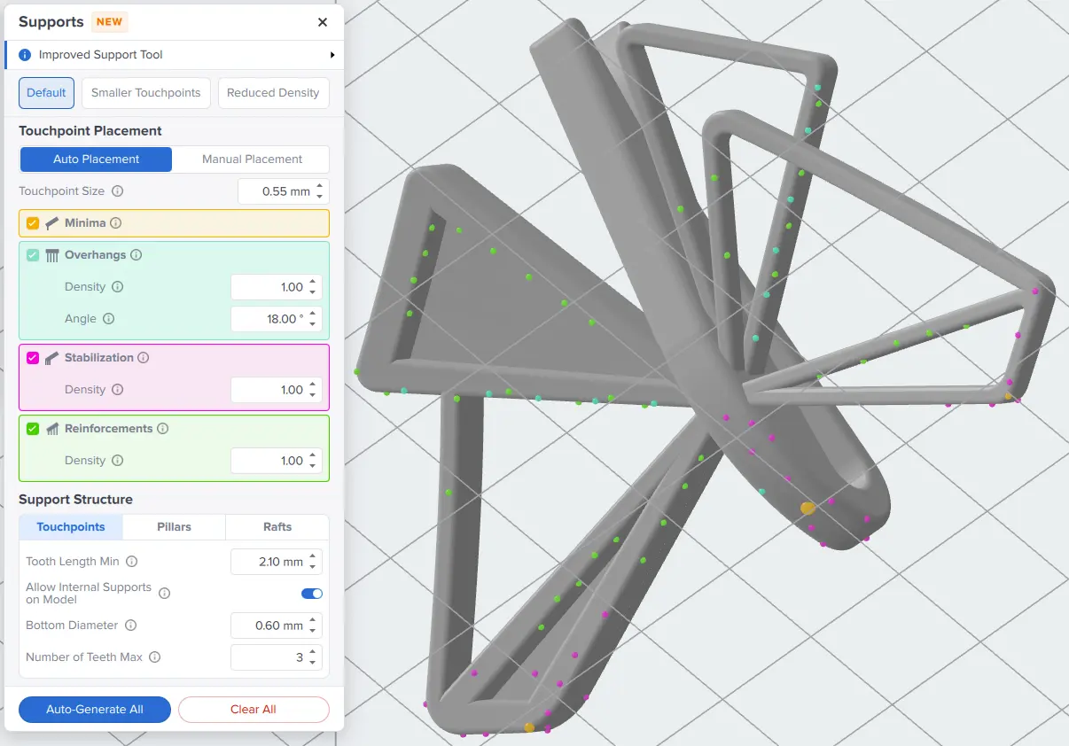
Starting with PreForm 3.51.0, you can control whether or not PreForm generates supports for minima, overhangs, additional minima stabilization, and bulk model reinforcement. These options are only available for supports settings marked Supports V1.

To control where and how PreForm generates supports:

  1. Click Supports. A dialog box opens.
  2. Click the checkbox to enable or disable a particular support type.
    • Minima: Enabling support generation for Minima adds touchpoints to the lowest points of the model to prevent print failures from unsupported geometry.
    • Overhangs: Enabling support generation for Overhangs adds touchpoints to downward-facing, low-angle surfaces.
      • Adjust the Angle parameter to control the threshold from the horizontal for placing overhang touchpoints. Surfaces at a lower angle than this value will receive support touchpoints.
    • Stabilization: Enabling support generation for Stabilization adds touchpoints to stabilize minima by placing additional touchpoints around them.
    • Reinforcements: Enabling support generation for Reinforcements adds touchpoints to improve the overall rigidity of the model, preventing shifting or warping during printing.
  3. If you have no models selected, click Auto-Generate All. Supports are added to all models on the build platform. Otherwise, if you have one or more models selected, click Auto-Generate Selected. Supports are added to the selected models.

You can also control the density of Overhangs, Stabilization, and Reinforcements touchpoints separately. For more information, see the section on controlling touchpoint density below.

Each support type is color-coded on your models for easy identification.

  • Minima: orange
  • Overhangs: teal
  • Stabilization: pink
  • Reinforcements: green

These colors match the sections for each touchpoint type in the Touchpoint Placement panel.

Color-coded support touchpoints in PreForm 3.52.0

Controlling touchpoint density

Touchpoints are areas of contact where the support structure and model meet. Changing the density of those touchpoints can affect print accuracy and success rate but also how easy or difficult the printed part is to post-process. Note that each density value is relative to other settings and may not start at 1.0.

Notice:

Parts with insufficient Density may fail to print. Increase Touchpoint Size to stabilize a part during printing and compensate for a lower Density value.

To adjust the Density value:

Supports V1Supports V2
  1. Click Supports. A dialog box opens.
  2. Adjust the density of a particular support type.
    • Overhangs: Controls the density of touchpoints on overhanging surfaces. Higher density can result in more accurate and reliable printing.
    • Stabilization: Controls the density of touchpoints are added around minima to improve model stability. Increase for tall or flexible parts that are prone to shifting.
    • Reinforcements: Controls the density of touchpoints added along the body of the part for reinforcement. Higher density can result in better layer registration and more reliable printing.
  3. If you have no models selected, click Auto-Generate All. Supports are added to all models on the build platform. Otherwise, if you have one or more models selected, click Auto-Generate Selected. Supports are added to the selected models.
  1. Click Supports. A dialog box opens.
  2. Adjust the Density value as desired:
    • Enter a number into the Density field.
    • Click an arrow in the Density field.
    • Hover the pointer over the Density field and use the scroll wheel.
  3. If you have no models selected, click Auto-Generate All. Supports are added to all models on the build platform. Otherwise, if you have one or more models selected, click Auto-Generate Selected. Supports are added to the selected models.

Controlling touchpoint density through print settings

With PreForm 3.48 or later, you can also reduce touchpoint density for certain resins with the Reduced Supports print setting. This can be useful if you want to optimize for surface finish without manually adjusting support parameters.

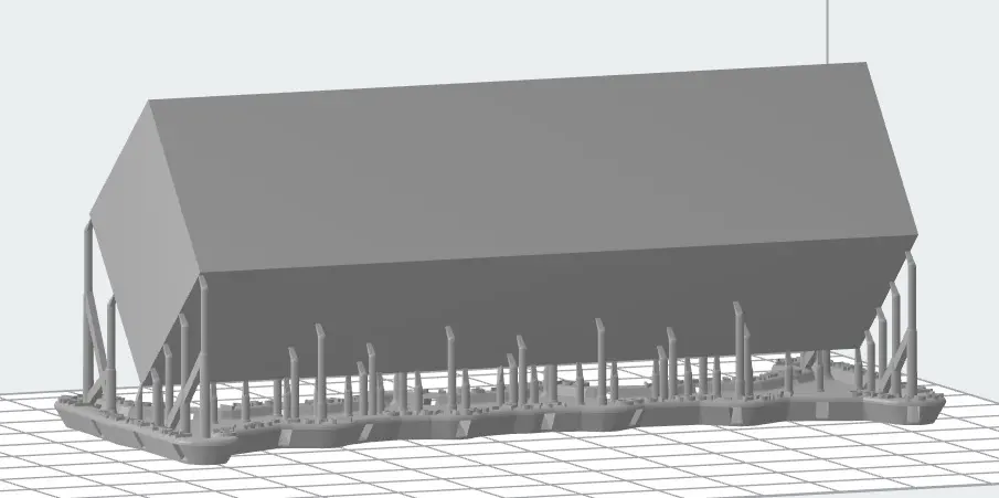
A model in Grey Resin V5 with default supports
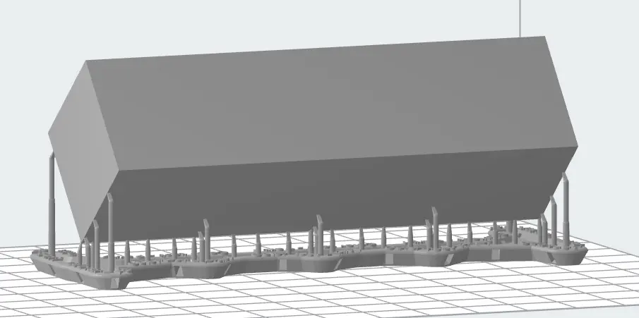
A model in Grey Resin V5 with supports generated with the Reduced Supports print setting

This print setting is available for Form 4 generation printers and the following resins:

  • Grey Resin V5
  • Clear Resin V5
  • Black Resin V5
  • White Resin V5
  • Tough 1500 Resin V1.1
  • Tough 2000 Resin
  • Durable Resin

Adjusting touchpoint geometry

One factor that affects post-processing is the distance between each main support pillar and the surface of your printed parts. Increasing this distance creates a larger gap, easing support removal. To adjust this distance:

  1. Click Supports. A dialog box opens.
  2. Click Touchpoints. A set of parameters appears.
  3. Adjust the Tooth Length Min parameter.
  4. If you have no models selected, click Auto-Generate All. Supports are added to all models on the build platform. Otherwise, if you have one or more models selected, click Auto-Generate Selected. Supports are added to the selected models.

Adding internal supports on the model

Internal supports are any supports with both ends touching the model, instead of one end connecting to the raft. Generate supports inside your model to secure overhangs and other hard-to-reach minima.

Tip:

As supports are generated or edited, PreForm can help identify regions that may require additional support. While the red shading is a tool to find and support minima, you may find other support settings to be equally effective for your needs.

To add internal supports:

  1. Click Supports. A dialog box opens.
  2. Click Touchpoints. A set of parameters appears.
  3. Enable the Allow Internal Supports on Model toggle.
  4. Adjust the internal support parameters.
    • Bottom Diameter: Sets the diameter of the base of an internal support where it connects to the model surface.
    • Number of Teeth Max: Sets the maximum number of base contact points that an internal support makes to distribute load on the model surface.
  5. If you have no models selected, click Auto-Generate All. Supports are added to all models on the build platform. Otherwise, if you have one or more models selected, click Auto-Generate Selected. Supports are added to the selected models.

Editing support pillar geometry

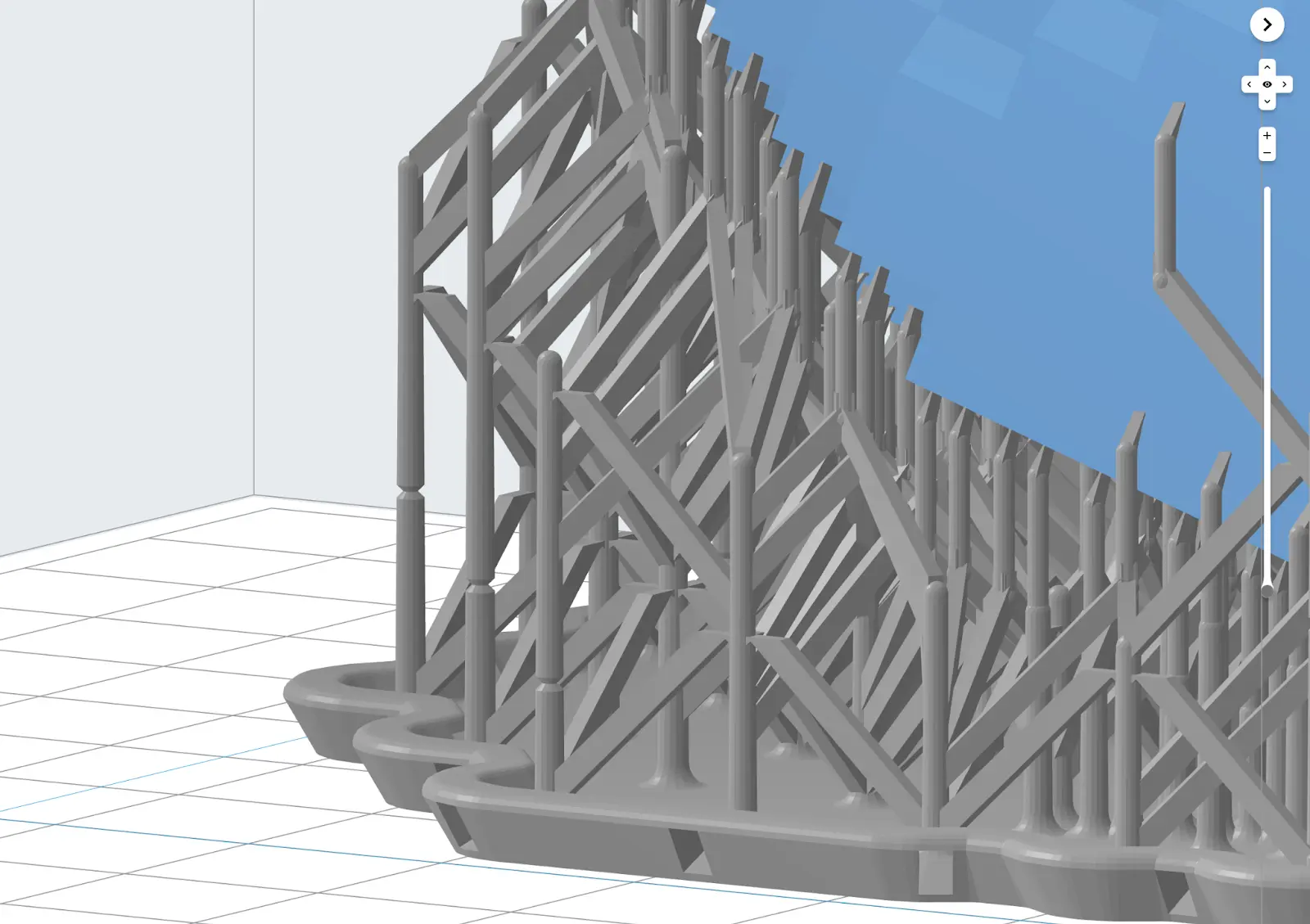
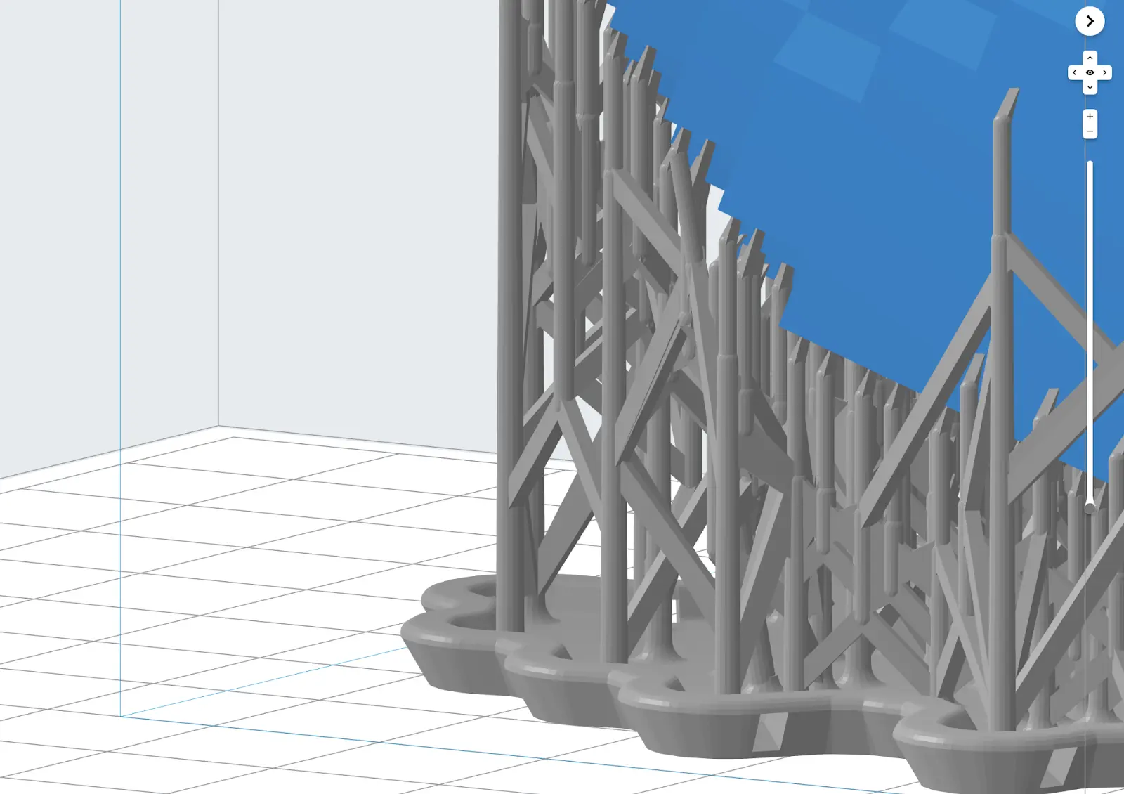
Pillars are the main portions of the support structure, reaching from the build platform to the touchpoint and printed part itself. Pillars can be supported by additional trusses.

To control the geometry of the pillars and supporting trusses:

  1. Click Supports. A dialog box opens.
  2. Click Pillars. A set of parameters appears.
  3. Select your desired Structure Type.
    • Classic: Standard PreForm support structure.
    • Lattice: Introduced with Supports V2 settings. Lattice supports are uniformly distributed along a grid. The crushable structure makes support removal fast, easy, and less likely to damage your part.
  4. Adjust the available pillar parameters.
    • Top Truss Width: Horizontal thickness of trusses at the top of the support structure, closest to the model.
    • Truss Width: Horizontal thickness of truss elements between pillars.
    • Truss Height: Vertical thickness of truss elements between pillars.
    • Lattice Size (XY) (Lattice structure type only): Horizontal distance between support pillars in lattice structure supports.
    • Lattice Size (Z) (Lattice structure type only): The maximum height of each lattice cell in lattice structure supports.
    • Trussed Pillar Top Diameter: Sets the diameter of the upper part of a trussed (cross-braced) support pillar. Decreasing this value reduces support structure stability and can cause print surface artifacts or failures.
    • Trussed Pillar Bottom Diameter: Sets the diameter of the lower part of a trussed support pillar, near the raft. Decreasing this value reduces support structure stability and can cause print surface artifacts or failures.
    • Trussing Distance From Model: Sets the distance from the model where cross-bracing on pillars begins. Increasing this value can allow for easier tool access during support removal but reduces support structure stability and can cause print surface artifacts.
    • Untrussed Pillar Diameter: Sets the diameter of support pillars for the portion between the model and the trussed section of the support pillar. Decreasing this value reduces support structure stability and can cause print surface artifacts or failures.
  5. If you have no models selected, click Auto-Generate All. Supports are added to all models on the build platform. Otherwise, if you have one or more models selected, click Auto-Generate Selected. Supports are added to the selected models.

Enabling and adjusting bundled supports

Bundled Supports are trussed in bundles to make them easier to remove. Bundled Supports are enabled by default for specific combinations of resins and layer thicknesses, but can be manually enabled otherwise.

To enable Bundled Supports:

  1. Click Supports. A dialog box opens.
  2. Click Pillars. A set of parameters appears.
  3. Select Bundled Supports. The box turns blue.
  4. If desired, adjust the Bundling Diameter. This parameter sets the target diameter for a group of bundled support pillars.
  5. If you have no models selected, click Auto-Generate All. Supports are added to all models on the build platform. Otherwise, if you have one or more models selected, click Auto-Generate Selected. PreForm generates bundled supports.

Changing the raft type

Choose between a Full Raft, Mini Rafts, or no raft by changing the Raft Type. Keeping the default Full Raft prints your model on a single, large raft. Selecting Mini Rafts creates multiple, smaller rafts—one for each vertical support. To print without a raft, select None to place a model directly on the build platform. 

Notice:

Select Full Raft to provide the greatest support and adhesion for your part.

Printing on Mini Rafts saves time and resin, but may require you to add additional support to a part. Mini Rafts are recommended for small jewelry applications and parts 30 mm to 40 mm in size. Print on Full Rafts for parts smaller than 30 mm for the highest likelihood of print success. Increase Density or Touchpoint Size to ensure all models are properly supported.

To adjust the Raft Type value:

  1. Click Supports. A dialog box opens.
  2. Click Raft. A set of parameters appears.
  3. Click the Raft Type field. A dropdown opens.
  4. Choose a raft type:
  5. Select Full Raft to place the model above a large base with supports.
  6. Select Mini Rafts to place the model on the build platform with supports.
  7. Select None to place the model directly on the build platform.
  8. If you have no models selected, click Auto-Generate All. Supports are added to all models on the build platform. Otherwise, if you have one or more models selected, click Auto-Generate Selected. The models are placed above the selected raft.

Adjusting raft geometry

Depending on the Raft Type you select, you can control various aspects of that raft’s geometry. To adjust the raft geometry:

  1. Click Supports. A dialog box opens.
  2. Click Raft. A set of parameters appears.
  3. Adjust the available parameters for your chosen raft type:
    • Full Raft
      • Raft Thickness: Sets the thickness of the full raft.
      • Height Above Raft: Sets the minimum distance between the model and the raft. Increasing this value can make supports easier to remove but also decreases stability of the bottom of the support structure and can cause print failures.
    • Mini Rafts
      • Raft Thickness: Sets the thickness of the mini rafts.
      • Height Above Raft: Sets the minimum distance between the model and the raft. Increasing this value can make supports easier to remove but also decreases stability of the bottom of the support structure and can cause print failures.
      • Raft Radius: Sets the radius of each individual mini raft. Larger rafts provide better adhesion to the build platform.
      • Merging Distance: Sets the distance at which nearby mini rafts will merge into a single, larger raft.
    • None
      • Raft Thickness: Sets the thickness of the mini rafts, if any are required.
      • Height Above Raft: Sets the minimum distance between the model and the raft. Increasing this value can make supports easier to remove.
      • Raft Radius: Sets the radius of each individual mini raft. Larger rafts provide better adhesion to the build platform.
      • Merging Distance: Sets the distance at which nearby mini rafts will merge into a single, larger raft.
      • Early Layer Merge: Flattens the model's initial layers up to the selected value to create a solid base for printing directly on the build platform.
      • Z-Compression Correction: Adds extra height to the initial layers to compensate for Z-axis compression, improving dimensional accuracy.
  4. If you have no models selected, click Auto-Generate All. Supports are added to all models on the build platform. Otherwise, if you have one or more models selected, click Auto-Generate Selected. Supports are added to the selected models.

Removing raft labels

A model's file name is used as the raft label. By default, a model’s name is generated on the raft of the support structure.

Tip:

Use Raft Label to keep track of different versions of printed parts.

To disable Raft Label on a model:

  1. Click Supports. A dialog box opens.
  2. Click Raft. A set of parameters appears.
  3. Deselect Raft Label. The box turns gray.
  4. If you have no models selected, click Auto-Generate All. Supports are added to all models on the build platform. Otherwise, if you have one or more models selected, click Auto-Generate Selected. The label is removed from the raft.

Enabling breakaway supports (PreForm 3.50.2 and earlier)

Depending on your model, resin, and support settings, support structures may be difficult to remove. PreForm can generate breakaway support structures with geometric features that make them easier to remove.

Note:

Formlabs recommends against using breakaway support structures if your model has features that could fail during printing, such as long flat spans.

To enable Breakaway Supports:

  1. Select the model in PreForm. Manipulators are overlaid on the model.
  2. Click Supports. A dialog box opens.
  3. Select Breakaway Supports. The box turns blue.

Note:

Breakaway support structures are not available for all resins. If breakaway supports are not available for your selected resin, the option is not visible.

  1. Click Auto-Generate Selected. The support structure is generated with breakaway supports.
A model in PreForm with breakaway supports.
A model in PreForm without breakaway supports.

Restoring default settings

To reset an edited parameter to its default value:

  1. Click Supports. A dialog box opens.
  2. Navigate to the edited parameter.
  3. Click the Reset value to default arrow icon to the left of the parameter’s current value. The parameter resets to its default value.